Page 1631 of 2399
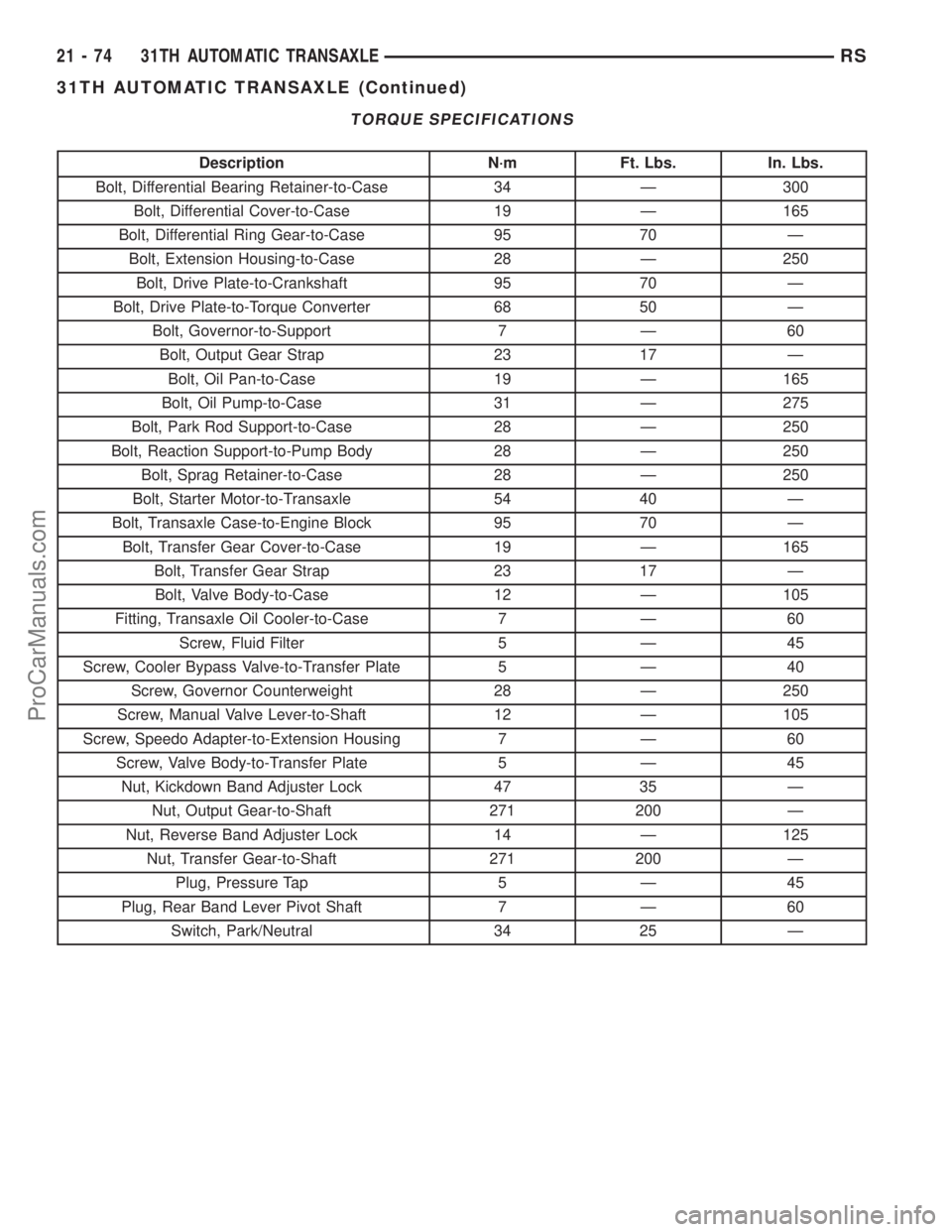
TORQUE SPECIFICATIONS
Description N´m Ft. Lbs. In. Lbs.
Bolt, Differential Bearing Retainer-to-Case 34 Ð 300
Bolt, Differential Cover-to-Case 19 Ð 165
Bolt, Differential Ring Gear-to-Case 95 70 Ð
Bolt, Extension Housing-to-Case 28 Ð 250
Bolt, Drive Plate-to-Crankshaft 95 70 Ð
Bolt, Drive Plate-to-Torque Converter 68 50 Ð
Bolt, Governor-to-Support 7 Ð 60
Bolt, Output Gear Strap 23 17 Ð
Bolt, Oil Pan-to-Case 19 Ð 165
Bolt, Oil Pump-to-Case 31 Ð 275
Bolt, Park Rod Support-to-Case 28 Ð 250
Bolt, Reaction Support-to-Pump Body 28 Ð 250
Bolt, Sprag Retainer-to-Case 28 Ð 250
Bolt, Starter Motor-to-Transaxle 54 40 Ð
Bolt, Transaxle Case-to-Engine Block 95 70 Ð
Bolt, Transfer Gear Cover-to-Case 19 Ð 165
Bolt, Transfer Gear Strap 23 17 Ð
Bolt, Valve Body-to-Case 12 Ð 105
Fitting, Transaxle Oil Cooler-to-Case 7 Ð 60
Screw, Fluid Filter 5 Ð 45
Screw, Cooler Bypass Valve-to-Transfer Plate 5 Ð 40
Screw, Governor Counterweight 28 Ð 250
Screw, Manual Valve Lever-to-Shaft 12 Ð 105
Screw, Speedo Adapter-to-Extension Housing 7 Ð 60
Screw, Valve Body-to-Transfer Plate 5 Ð 45
Nut, Kickdown Band Adjuster Lock 47 35 Ð
Nut, Output Gear-to-Shaft 271 200 Ð
Nut, Reverse Band Adjuster Lock 14 Ð 125
Nut, Transfer Gear-to-Shaft 271 200 Ð
Plug, Pressure Tap 5 Ð 45
Plug, Rear Band Lever Pivot Shaft 7 Ð 60
Switch, Park/Neutral 34 25 Ð
21 - 74 31TH AUTOMATIC TRANSAXLERS
31TH AUTOMATIC TRANSAXLE (Continued)
ProCarManuals.com
Page 1635 of 2399
Differential Tool L-4436A
Housing Remover Adapter L-4437
Starter Nut L-4439
Transfer Shaft Remover-Installer L-4512
Bearing Cup Remover L-4517
Special Jaw Set L-4518
Installer L-4520
End Play Socket Set 8266
Bearing Splitter P-334
21 - 78 31TH AUTOMATIC TRANSAXLERS
31TH AUTOMATIC TRANSAXLE (Continued)
ProCarManuals.com
Page 1648 of 2399
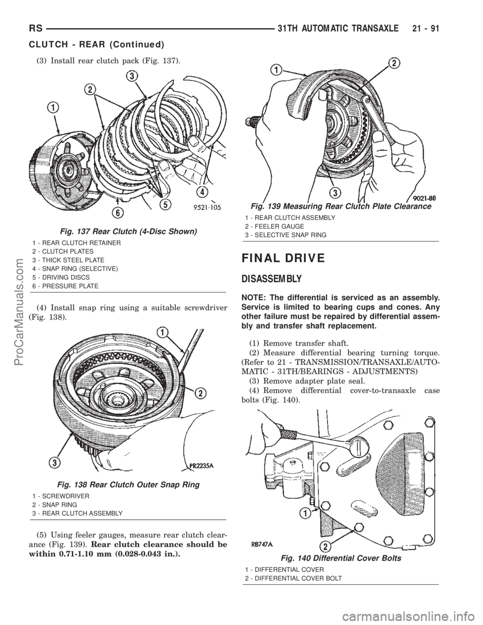
(3) Install rear clutch pack (Fig. 137).
(4) Install snap ring using a suitable screwdriver
(Fig. 138).
(5) Using feeler gauges, measure rear clutch clear-
ance (Fig. 139).Rear clutch clearance should be
within 0.71-1.10 mm (0.028-0.043 in.).
FINAL DRIVE
DISASSEMBLY
NOTE: The differential is serviced as an assembly.
Service is limited to bearing cups and cones. Any
other failure must be repaired by differential assem-
bly and transfer shaft replacement.
(1) Remove transfer shaft.
(2) Measure differential bearing turning torque.
(Refer to 21 - TRANSMISSION/TRANSAXLE/AUTO-
MATIC - 31TH/BEARINGS - ADJUSTMENTS)
(3) Remove adapter plate seal.
(4) Remove differential cover-to-transaxle case
bolts (Fig. 140).
Fig. 137 Rear Clutch (4-Disc Shown)
1 - REAR CLUTCH RETAINER
2 - CLUTCH PLATES
3 - THICK STEEL PLATE
4 - SNAP RING (SELECTIVE)
5 - DRIVING DISCS
6 - PRESSURE PLATE
Fig. 138 Rear Clutch Outer Snap Ring
1 - SCREWDRIVER
2 - SNAP RING
3 - REAR CLUTCH ASSEMBLY
Fig. 139 Measuring Rear Clutch Plate Clearance
1 - REAR CLUTCH ASSEMBLY
2 - FEELER GAUGE
3 - SELECTIVE SNAP RING
Fig. 140 Differential Cover Bolts
1 - DIFFERENTIAL COVER
2 - DIFFERENTIAL COVER BOLT
RS31TH AUTOMATIC TRANSAXLE21-91
CLUTCH - REAR (Continued)
ProCarManuals.com
Page 1649 of 2399
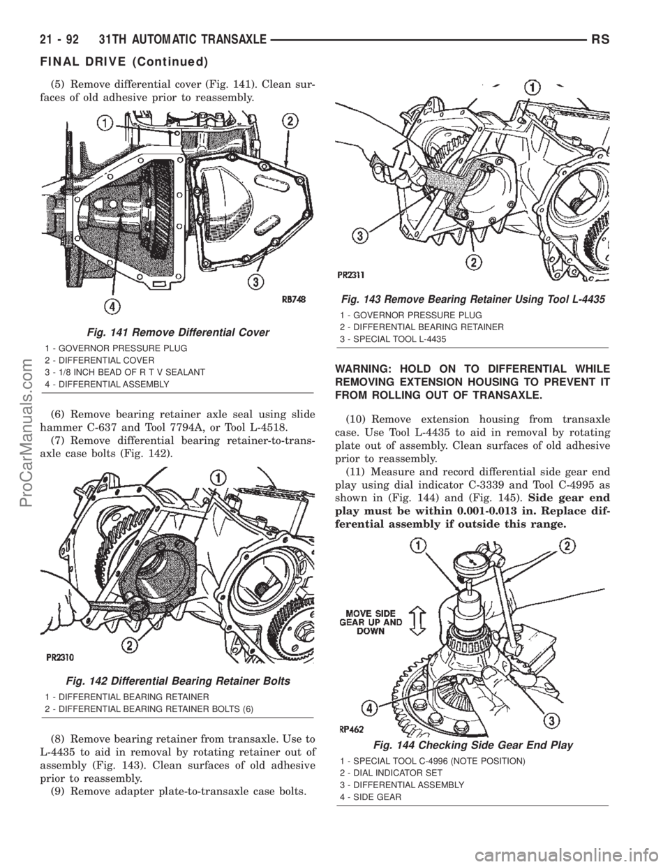
(5) Remove differential cover (Fig. 141). Clean sur-
faces of old adhesive prior to reassembly.
(6) Remove bearing retainer axle seal using slide
hammer C-637 and Tool 7794A, or Tool L-4518.
(7) Remove differential bearing retainer-to-trans-
axle case bolts (Fig. 142).
(8) Remove bearing retainer from transaxle. Use to
L-4435 to aid in removal by rotating retainer out of
assembly (Fig. 143). Clean surfaces of old adhesive
prior to reassembly.
(9) Remove adapter plate-to-transaxle case bolts.WARNING: HOLD ON TO DIFFERENTIAL WHILE
REMOVING EXTENSION HOUSING TO PREVENT IT
FROM ROLLING OUT OF TRANSAXLE.
(10) Remove extension housing from transaxle
case. Use Tool L-4435 to aid in removal by rotating
plate out of assembly. Clean surfaces of old adhesive
prior to reassembly.
(11) Measure and record differential side gear end
play using dial indicator C-3339 and Tool C-4995 as
shown in (Fig. 144) and (Fig. 145).Side gear end
play must be within 0.001-0.013 in. Replace dif-
ferential assembly if outside this range.
Fig. 141 Remove Differential Cover
1 - GOVERNOR PRESSURE PLUG
2 - DIFFERENTIAL COVER
3 - 1/8 INCH BEAD OF R T V SEALANT
4 - DIFFERENTIAL ASSEMBLY
Fig. 142 Differential Bearing Retainer Bolts
1 - DIFFERENTIAL BEARING RETAINER
2 - DIFFERENTIAL BEARING RETAINER BOLTS (6)
Fig. 143 Remove Bearing Retainer Using Tool L-4435
1 - GOVERNOR PRESSURE PLUG
2 - DIFFERENTIAL BEARING RETAINER
3 - SPECIAL TOOL L-4435
Fig. 144 Checking Side Gear End Play
1 - SPECIAL TOOL C-4996 (NOTE POSITION)
2 - DIAL INDICATOR SET
3 - DIFFERENTIAL ASSEMBLY
4 - SIDE GEAR
21 - 92 31TH AUTOMATIC TRANSAXLERS
FINAL DRIVE (Continued)
ProCarManuals.com
Page 1650 of 2399
(12) Remove differential bearing cone (from exten-
sion housing side) using Tool C-293, and adapters
C-293-3, and C-293-36 (Fig. 146).(13) Set up tools as shown in (Fig. 147) and (Fig.
148) to facilitate differential bearing removal from
ring gear side.
Fig. 145 Checking Side Gear End Play (Typical)
1 - SPECIAL TOOL C-4996 (NOTE POSITION)
2 - DIAL INDICATOR SET
3 - DIFFERENTIAL ASSEMBLY
Fig. 146 Remove Differential Bearing Cone
(Extension Housing Side)
1 - SPECIAL TOOL C-293
2 - SPECIAL TOOL C-293-36
3 - SPECIAL TOOL C-293-3
Fig. 147 Differential Bearing Removal Set-Up (Ring
Gear Side)
1 - SPECIAL TOOL L-4539-2
2 - SPECIAL TOOL 5048
3 - SPECIAL TOOL 5048-4
Fig. 148 Position Tool 5048 Over Button and Collets
at Differential Bearing
1 - SPECIAL TO0L 5048
2 - DIFFERENTIAL
3 - SPECIAL TOOL 5048-4
RS31TH AUTOMATIC TRANSAXLE21-93
FINAL DRIVE (Continued)
ProCarManuals.com
Page 1651 of 2399
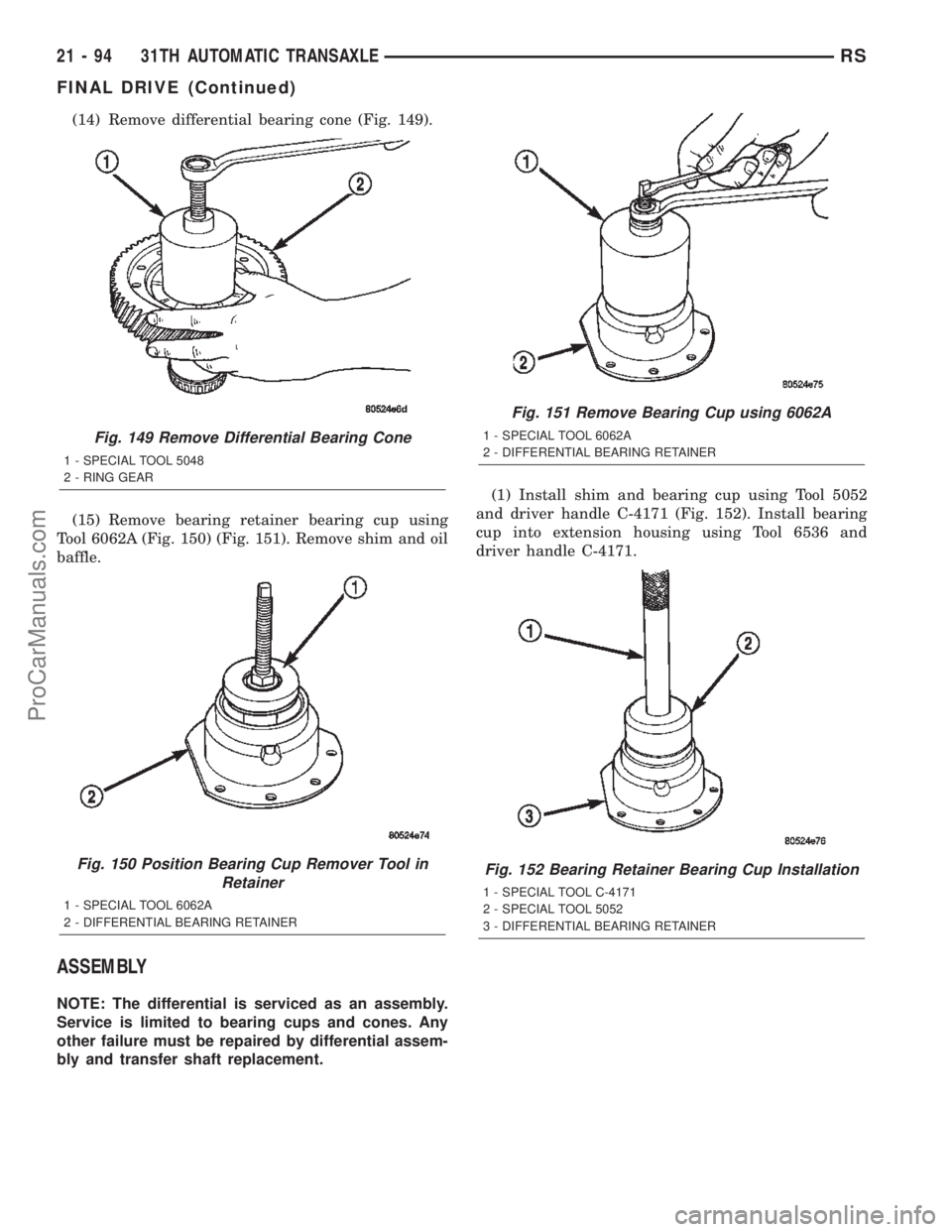
(14) Remove differential bearing cone (Fig. 149).
(15) Remove bearing retainer bearing cup using
Tool 6062A (Fig. 150) (Fig. 151). Remove shim and oil
baffle.
ASSEMBLY
NOTE: The differential is serviced as an assembly.
Service is limited to bearing cups and cones. Any
other failure must be repaired by differential assem-
bly and transfer shaft replacement.(1) Install shim and bearing cup using Tool 5052
and driver handle C-4171 (Fig. 152). Install bearing
cup into extension housing using Tool 6536 and
driver handle C-4171.
Fig. 149 Remove Differential Bearing Cone
1 - SPECIAL TOOL 5048
2 - RING GEAR
Fig. 150 Position Bearing Cup Remover Tool in
Retainer
1 - SPECIAL TOOL 6062A
2 - DIFFERENTIAL BEARING RETAINER
Fig. 151 Remove Bearing Cup using 6062A
1 - SPECIAL TOOL 6062A
2 - DIFFERENTIAL BEARING RETAINER
Fig. 152 Bearing Retainer Bearing Cup Installation
1 - SPECIAL TOOL C-4171
2 - SPECIAL TOOL 5052
3 - DIFFERENTIAL BEARING RETAINER
21 - 94 31TH AUTOMATIC TRANSAXLERS
FINAL DRIVE (Continued)
ProCarManuals.com
Page 1652 of 2399
(2) Position bearing cone onto differential (Fig.
153), and install bearing cone using Tool 6536 and
driver handle C-4171 (Fig. 154).(3) Measure side gear end play using dial indicator
C-3339 and Tool C-4996 (Fig. 155) (Fig. 156).Side
gear end play must be between 0.001 and 0.013
in.
Fig. 153 Position Bearing Cone Onto Differential
1 - DIFFERENTIAL ASSEMBLY
2 - DIFFERENTIAL BEARING
Fig. 154 Install Differential Bearing Cone
1 - SPECIAL TOOL C-4171
2 - SPECIAL TOOL 6536
3 - DIFFERENTIAL ASSEMBLY
Fig. 155 Checking Side Gear End Play
1 - SPECIAL TOOL C-4996 (NOTE POSITION)
2 - DIAL INDICATOR SET
3 - DIFFERENTIAL ASSEMBLY
4 - SIDE GEAR
Fig. 156 Checking Side Gear End Play (Typical)
1 - SPECIAL TOOL C-4996 (NOTE POSITION)
2 - DIAL INDICATOR SET
3 - DIFFERENTIAL ASSEMBLY
RS31TH AUTOMATIC TRANSAXLE21-95
FINAL DRIVE (Continued)
ProCarManuals.com
Page 1653 of 2399
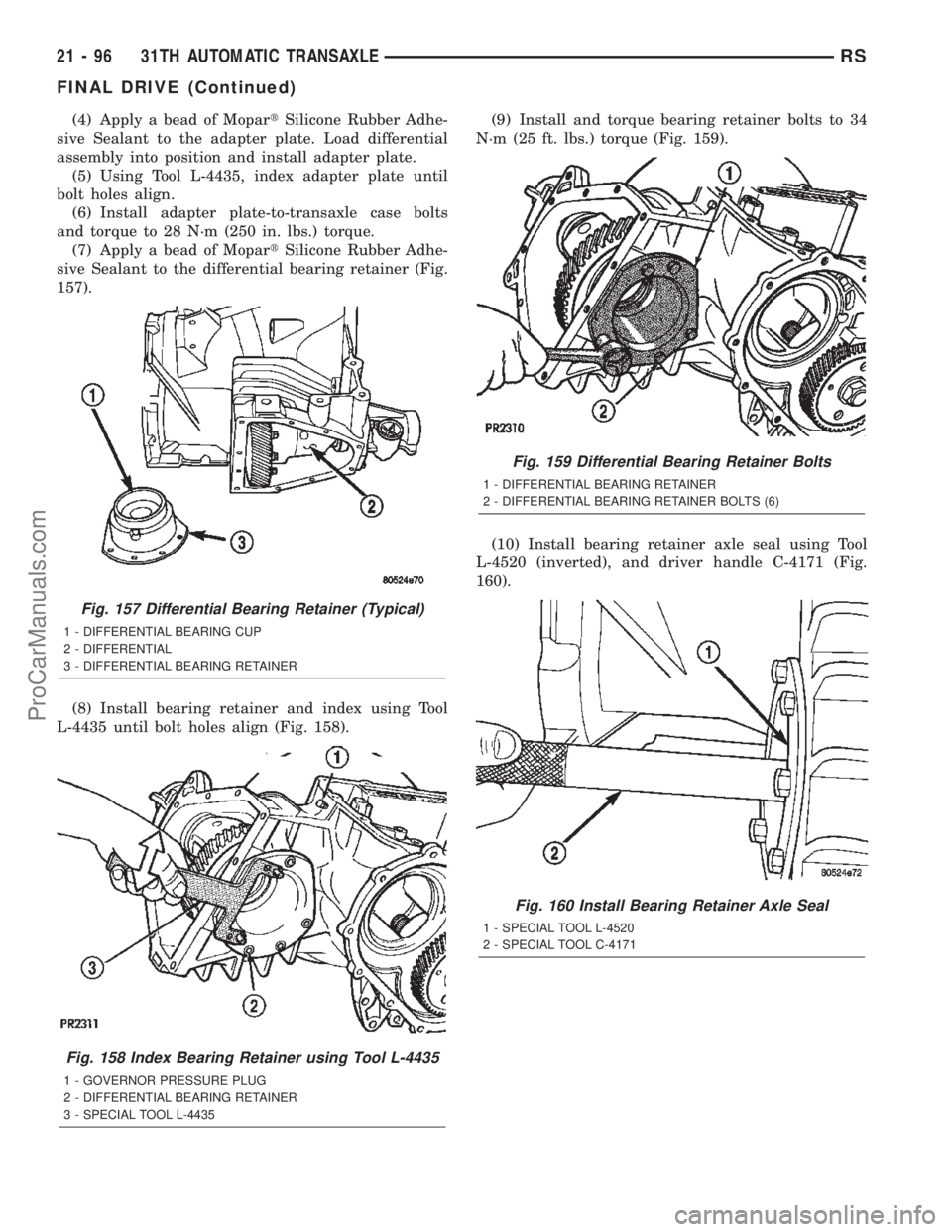
(4) Apply a bead of MopartSilicone Rubber Adhe-
sive Sealant to the adapter plate. Load differential
assembly into position and install adapter plate.
(5) Using Tool L-4435, index adapter plate until
bolt holes align.
(6) Install adapter plate-to-transaxle case bolts
and torque to 28 N´m (250 in. lbs.) torque.
(7) Apply a bead of MopartSilicone Rubber Adhe-
sive Sealant to the differential bearing retainer (Fig.
157).
(8) Install bearing retainer and index using Tool
L-4435 until bolt holes align (Fig. 158).(9) Install and torque bearing retainer bolts to 34
N´m (25 ft. lbs.) torque (Fig. 159).
(10) Install bearing retainer axle seal using Tool
L-4520 (inverted), and driver handle C-4171 (Fig.
160).
Fig. 157 Differential Bearing Retainer (Typical)
1 - DIFFERENTIAL BEARING CUP
2 - DIFFERENTIAL
3 - DIFFERENTIAL BEARING RETAINER
Fig. 158 Index Bearing Retainer using Tool L-4435
1 - GOVERNOR PRESSURE PLUG
2 - DIFFERENTIAL BEARING RETAINER
3 - SPECIAL TOOL L-4435
Fig. 159 Differential Bearing Retainer Bolts
1 - DIFFERENTIAL BEARING RETAINER
2 - DIFFERENTIAL BEARING RETAINER BOLTS (6)
Fig. 160 Install Bearing Retainer Axle Seal
1 - SPECIAL TOOL L-4520
2 - SPECIAL TOOL C-4171
21 - 96 31TH AUTOMATIC TRANSAXLERS
FINAL DRIVE (Continued)
ProCarManuals.com