2002 CHRYSLER VOYAGER Brake line OD
[x] Cancel search: Brake line ODPage 1103 of 2399
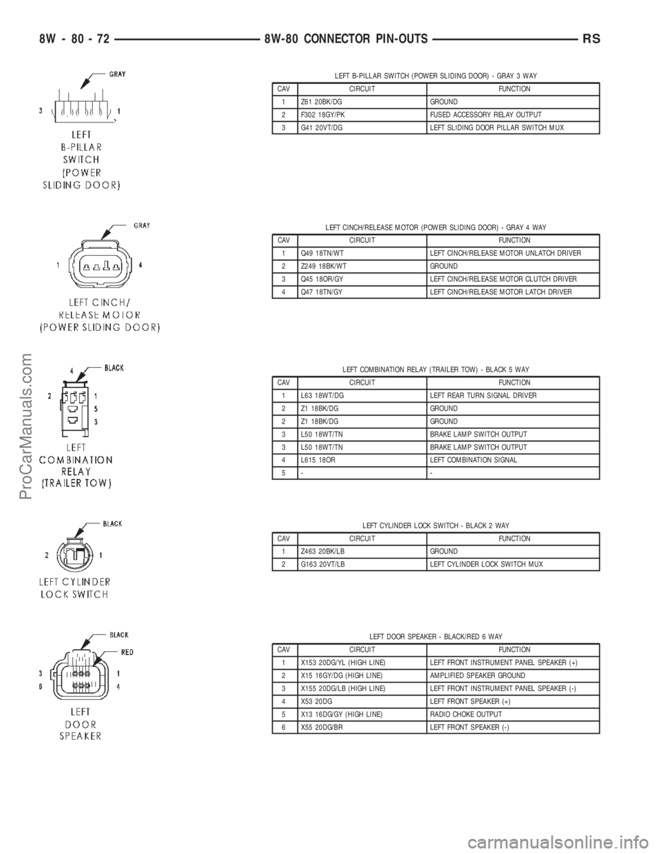
LEFT B-PILLAR SWITCH (POWER SLIDING DOOR) - GRAY 3 WAY
CAV CIRCUIT FUNCTION
1 Z61 20BK/DG GROUND
2 F302 18GY/PK FUSED ACCESSORY RELAY OUTPUT
3 G41 20VT/DG LEFT SLIDING DOOR PILLAR SWITCH MUX
LEFT CINCH/RELEASE MOTOR (POWER SLIDING DOOR) - GRAY 4 WAY
CAV CIRCUIT FUNCTION
1 Q49 18TN/WT LEFT CINCH/RELEASE MOTOR UNLATCH DRIVER
2 Z249 18BK/WT GROUND
3 Q45 18OR/GY LEFT CINCH/RELEASE MOTOR CLUTCH DRIVER
4 Q47 18TN/GY LEFT CINCH/RELEASE MOTOR LATCH DRIVER
LEFT COMBINATION RELAY (TRAILER TOW) - BLACK 5 WAY
CAV CIRCUIT FUNCTION
1 L63 18WT/DG LEFT REAR TURN SIGNAL DRIVER
2 Z1 18BK/DG GROUND
2 Z1 18BK/DG GROUND
3 L50 18WT/TN BRAKE LAMP SWITCH OUTPUT
3 L50 18WT/TN BRAKE LAMP SWITCH OUTPUT
4 L615 18OR LEFT COMBINATION SIGNAL
5- -
LEFT CYLINDER LOCK SWITCH - BLACK 2 WAY
CAV CIRCUIT FUNCTION
1 Z463 20BK/LB GROUND
2 G163 20VT/LB LEFT CYLINDER LOCK SWITCH MUX
LEFT DOOR SPEAKER - BLACK/RED 6 WAY
CAV CIRCUIT FUNCTION
1 X153 20DG/YL (HIGH LINE) LEFT FRONT INSTRUMENT PANEL SPEAKER (+)
2 X15 16GY/DG (HIGH LINE) AMPLIFIED SPEAKER GROUND
3 X155 20DG/LB (HIGH LINE) LEFT FRONT INSTRUMENT PANEL SPEAKER (-)
4 X53 20DG LEFT FRONT SPEAKER (+)
5 X13 16DG/GY (HIGH LINE) RADIO CHOKE OUTPUT
6 X55 20DG/BR LEFT FRONT SPEAKER (-)
8W - 80 - 72 8W-80 CONNECTOR PIN-OUTSRS
ProCarManuals.com
Page 1134 of 2399
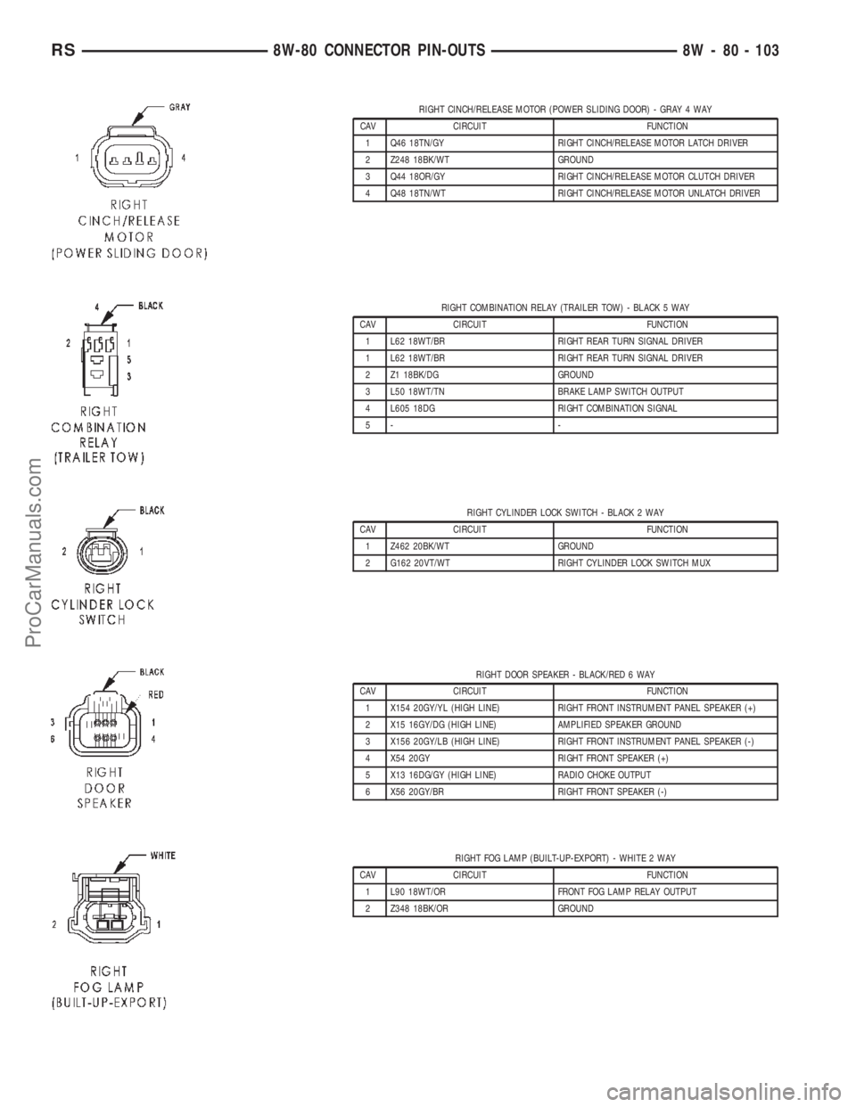
RIGHT CINCH/RELEASE MOTOR (POWER SLIDING DOOR) - GRAY 4 WAY
CAV CIRCUIT FUNCTION
1 Q46 18TN/GY RIGHT CINCH/RELEASE MOTOR LATCH DRIVER
2 Z248 18BK/WT GROUND
3 Q44 18OR/GY RIGHT CINCH/RELEASE MOTOR CLUTCH DRIVER
4 Q48 18TN/WT RIGHT CINCH/RELEASE MOTOR UNLATCH DRIVER
RIGHT COMBINATION RELAY (TRAILER TOW) - BLACK 5 WAY
CAV CIRCUIT FUNCTION
1 L62 18WT/BR RIGHT REAR TURN SIGNAL DRIVER
1 L62 18WT/BR RIGHT REAR TURN SIGNAL DRIVER
2 Z1 18BK/DG GROUND
3 L50 18WT/TN BRAKE LAMP SWITCH OUTPUT
4 L605 18DG RIGHT COMBINATION SIGNAL
5- -
RIGHT CYLINDER LOCK SWITCH - BLACK 2 WAY
CAV CIRCUIT FUNCTION
1 Z462 20BK/WT GROUND
2 G162 20VT/WT RIGHT CYLINDER LOCK SWITCH MUX
RIGHT DOOR SPEAKER - BLACK/RED 6 WAY
CAV CIRCUIT FUNCTION
1 X154 20GY/YL (HIGH LINE) RIGHT FRONT INSTRUMENT PANEL SPEAKER (+)
2 X15 16GY/DG (HIGH LINE) AMPLIFIED SPEAKER GROUND
3 X156 20GY/LB (HIGH LINE) RIGHT FRONT INSTRUMENT PANEL SPEAKER (-)
4 X54 20GY RIGHT FRONT SPEAKER (+)
5 X13 16DG/GY (HIGH LINE) RADIO CHOKE OUTPUT
6 X56 20GY/BR RIGHT FRONT SPEAKER (-)
RIGHT FOG LAMP (BUILT-UP-EXPORT) - WHITE 2 WAY
CAV CIRCUIT FUNCTION
1 L90 18WT/OR FRONT FOG LAMP RELAY OUTPUT
2 Z348 18BK/OR GROUND
RS8W-80 CONNECTOR PIN-OUTS8W - 80 - 103
ProCarManuals.com
Page 1138 of 2399
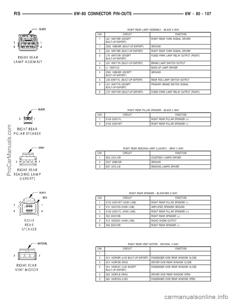
RIGHT REAR LAMP ASSEMBLY - BLACK 6 WAY
CAV CIRCUIT FUNCTION
1 L62 18WT/BR (EXCEPT
BUILT-UP-EXPORT)RIGHT REAR TURN SIGNAL DRIVER
1 Z362 18BK/BR (BUILT-UP-EXPORT) GROUND
2 L62 18WT/BR (BUILT-UP-EXPORT) RIGHT REAR TURN SIGNAL DRIVER
3 L78 18WT/OR (EXCEPT
BUILT-UP-EXPORT)FUSED PARK LAMP RELAY OUTPUT (RIGHT)
3 L50 18WT/TN (BUILT-UP-EXPORT) BRAKE LAMP SWITCH OUTPUT
4 L1 18WT/LG BACK-UP LAMP DRIVER
5 Z362 18BK/BR (EXCEPT
BUILT-UP-EXPORT)GROUND
5 L38 20WT/YL (BUILT-UP-EXPORT) REAR FOG LAMP SWITCH OUTPUT
6 L50 18WT/TN (EXCEPT
BUILT-UP-EXPORT)PRIMARY BRAKE SWITCH SIGNAL
6 L78 18WT/OR (BUILT-UP-EXPORT) FUSED PARK LAMP RELAY OUTPUT (RIGHT)
RIGHT REAR PILLAR SPEAKER - BLACK 2 WAY
CAV CIRCUIT FUNCTION
1 X158 20GY/YL RIGHT REAR PILLAR SPEAKER (+)
2 X152 20GY/WT RIGHT REAR PILLAR SPEAKER (-)
RIGHT REAR READING LAMP (LUXURY) - GRAY 3 WAY
CAV CIRCUIT FUNCTION
1 M22 20YL/OR COURTESY LAMPS DRIVER
2 Z327 20BK/OR GROUND
3 M27 20YL/LB READING LAMPS DRIVER
RIGHT REAR SPEAKER - BLACK/RED 6 WAY
CAV CIRCUIT FUNCTION
1 X152 20GY/WT (HIGH LINE) RIGHT REAR PILLAR SPEAKER (-)
2 X15 16GY/DG (HIGH LINE) AMPLIFIED SPEAKER GROUND
3 X158 20GY/YL (HIGH LINE) RIGHT REAR PILLAR SPEAKER (+)
4 X52 20GY/DB RIGHT REAR SPEAKER (+)
5 X13 16DG/GY (HIGH LINE) RADIO CHOKE OUTPUT
6 X58 20GY/OR RIGHT REAR SPEAKER (-)
RIGHT REAR VENT MOTOR - NATURAL 3 WAY
CAV CIRCUIT FUNCTION
1- -
2 Q14 16OR/BR (LHD BUILT-UP-EXPORT) PASSENGER SIDE REAR WINDOW CLOSE
2 Q13 16OR/DB (RHD) DRIVER SIDE REAR WINDOW CLOSE
2 Q14 16OR/GY (LHD EXCEPT
BUILT-UP-EXPORT)PASSENGER SIDE REAR WINDOW CLOSE
3 Q23 16OR/LB (RHD) DRIVER SIDE REAR WINDOW OPEN
3 Q24 16OR/DG (LHD) PASSENGER SIDE REAR WINDOW OPEN
RS8W-80 CONNECTOR PIN-OUTS8W - 80 - 107
ProCarManuals.com
Page 1261 of 2399
INTAKE MANIFOLD - UPPER
REMOVAL
(1) Disconnect negative cable from battery.
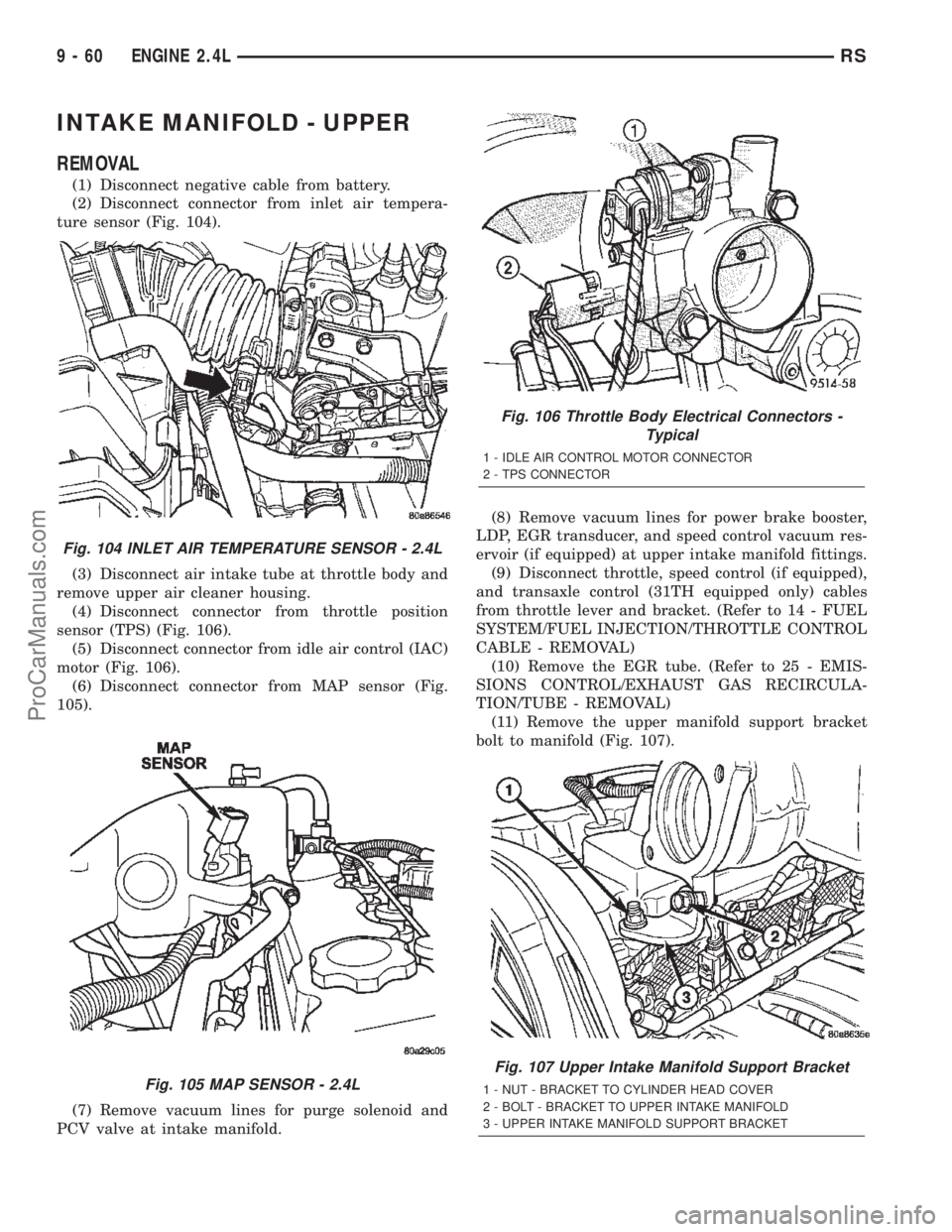
(2) Disconnect connector from inlet air tempera-
ture sensor (Fig. 104).
(3) Disconnect air intake tube at throttle body and
remove upper air cleaner housing.
(4) Disconnect connector from throttle position
sensor (TPS) (Fig. 106).
(5) Disconnect connector from idle air control (IAC)
motor (Fig. 106).
(6) Disconnect connector from MAP sensor (Fig.
105).
(7) Remove vacuum lines for purge solenoid and
PCV valve at intake manifold.(8) Remove vacuum lines for power brake booster,
LDP, EGR transducer, and speed control vacuum res-
ervoir (if equipped) at upper intake manifold fittings.
(9) Disconnect throttle, speed control (if equipped),
and transaxle control (31TH equipped only) cables
from throttle lever and bracket. (Refer to 14 - FUEL
SYSTEM/FUEL INJECTION/THROTTLE CONTROL
CABLE - REMOVAL)
(10) Remove the EGR tube. (Refer to 25 - EMIS-
SIONS CONTROL/EXHAUST GAS RECIRCULA-
TION/TUBE - REMOVAL)
(11) Remove the upper manifold support bracket
bolt to manifold (Fig. 107).
Fig. 104 INLET AIR TEMPERATURE SENSOR - 2.4L
Fig. 105 MAP SENSOR - 2.4L
Fig. 106 Throttle Body Electrical Connectors -
Typical
1 - IDLE AIR CONTROL MOTOR CONNECTOR
2 - TPS CONNECTOR
Fig. 107 Upper Intake Manifold Support Bracket
1 - NUT - BRACKET TO CYLINDER HEAD COVER
2 - BOLT - BRACKET TO UPPER INTAKE MANIFOLD
3 - UPPER INTAKE MANIFOLD SUPPORT BRACKET
9 - 60 ENGINE 2.4LRS
ProCarManuals.com
Page 1262 of 2399
(12) Remove engine oil dipstick from tube.
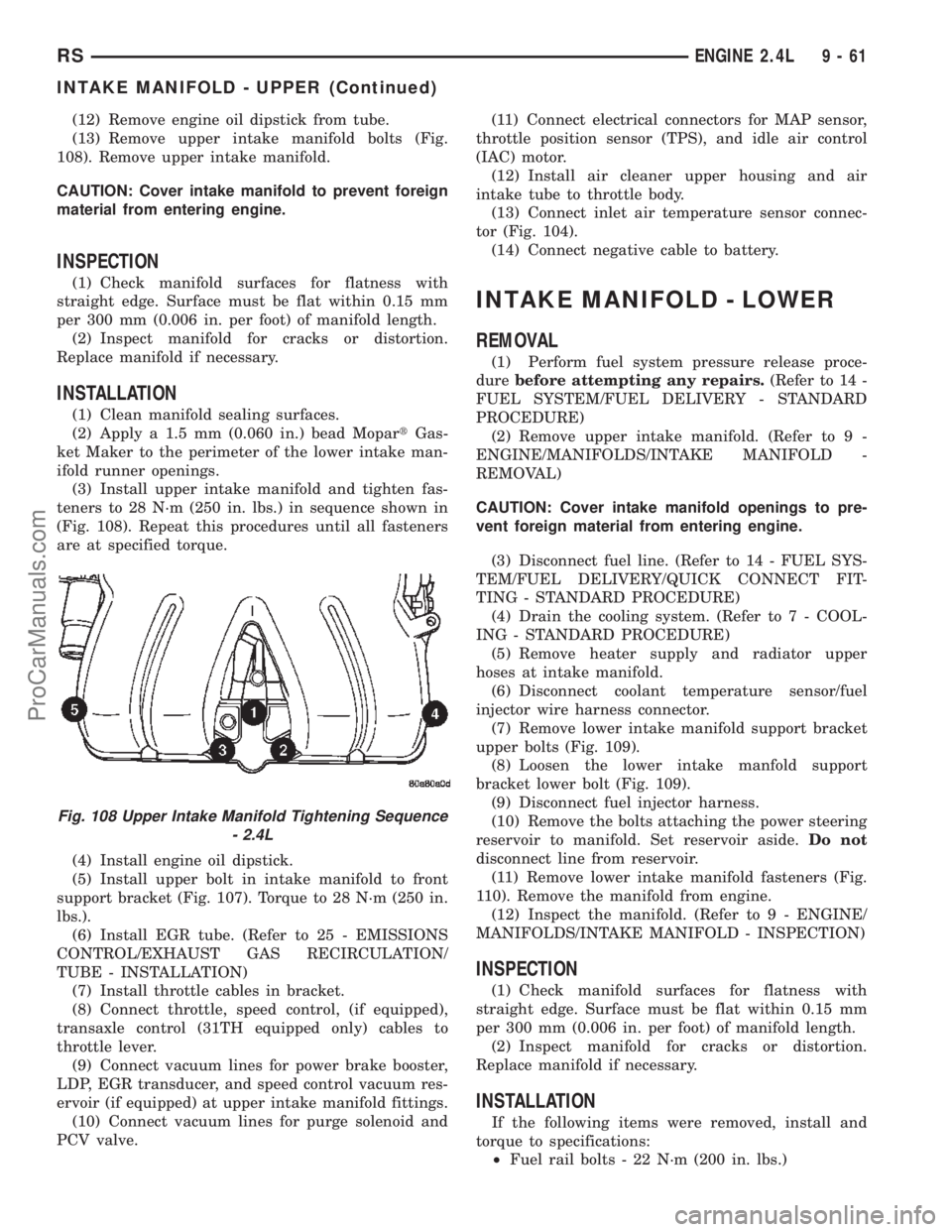
(13) Remove upper intake manifold bolts (Fig.
108). Remove upper intake manifold.
CAUTION: Cover intake manifold to prevent foreign
material from entering engine.
INSPECTION
(1) Check manifold surfaces for flatness with
straight edge. Surface must be flat within 0.15 mm
per 300 mm (0.006 in. per foot) of manifold length.
(2) Inspect manifold for cracks or distortion.
Replace manifold if necessary.
INSTALLATION
(1) Clean manifold sealing surfaces.
(2) Apply a 1.5 mm (0.060 in.) bead MopartGas-
ket Maker to the perimeter of the lower intake man-
ifold runner openings.
(3) Install upper intake manifold and tighten fas-
teners to 28 N´m (250 in. lbs.) in sequence shown in
(Fig. 108). Repeat this procedures until all fasteners
are at specified torque.
(4) Install engine oil dipstick.
(5) Install upper bolt in intake manifold to front
support bracket (Fig. 107). Torque to 28 N´m (250 in.
lbs.).
(6) Install EGR tube. (Refer to 25 - EMISSIONS
CONTROL/EXHAUST GAS RECIRCULATION/
TUBE - INSTALLATION)
(7) Install throttle cables in bracket.
(8) Connect throttle, speed control, (if equipped),
transaxle control (31TH equipped only) cables to
throttle lever.
(9) Connect vacuum lines for power brake booster,
LDP, EGR transducer, and speed control vacuum res-
ervoir (if equipped) at upper intake manifold fittings.
(10) Connect vacuum lines for purge solenoid and
PCV valve.(11) Connect electrical connectors for MAP sensor,
throttle position sensor (TPS), and idle air control
(IAC) motor.
(12) Install air cleaner upper housing and air
intake tube to throttle body.
(13) Connect inlet air temperature sensor connec-
tor (Fig. 104).
(14) Connect negative cable to battery.
INTAKE MANIFOLD - LOWER
REMOVAL
(1) Perform fuel system pressure release proce-
durebefore attempting any repairs.(Refer to 14 -
FUEL SYSTEM/FUEL DELIVERY - STANDARD
PROCEDURE)
(2) Remove upper intake manifold. (Refer to 9 -
ENGINE/MANIFOLDS/INTAKE MANIFOLD -
REMOVAL)
CAUTION: Cover intake manifold openings to pre-
vent foreign material from entering engine.
(3) Disconnect fuel line. (Refer to 14 - FUEL SYS-
TEM/FUEL DELIVERY/QUICK CONNECT FIT-
TING - STANDARD PROCEDURE)
(4) Drain the cooling system. (Refer to 7 - COOL-
ING - STANDARD PROCEDURE)
(5) Remove heater supply and radiator upper
hoses at intake manifold.
(6) Disconnect coolant temperature sensor/fuel
injector wire harness connector.
(7) Remove lower intake manifold support bracket
upper bolts (Fig. 109).
(8) Loosen the lower intake manfold support
bracket lower bolt (Fig. 109).
(9) Disconnect fuel injector harness.
(10) Remove the bolts attaching the power steering
reservoir to manifold. Set reservoir aside.Do not
disconnect line from reservoir.
(11) Remove lower intake manifold fasteners (Fig.
110). Remove the manifold from engine.
(12) Inspect the manifold. (Refer to 9 - ENGINE/
MANIFOLDS/INTAKE MANIFOLD - INSPECTION)
INSPECTION
(1) Check manifold surfaces for flatness with
straight edge. Surface must be flat within 0.15 mm
per 300 mm (0.006 in. per foot) of manifold length.
(2) Inspect manifold for cracks or distortion.
Replace manifold if necessary.
INSTALLATION
If the following items were removed, install and
torque to specifications:
²Fuel rail bolts - 22 N´m (200 in. lbs.)
Fig. 108 Upper Intake Manifold Tightening Sequence
- 2.4L
RSENGINE 2.4L9-61
INTAKE MANIFOLD - UPPER (Continued)
ProCarManuals.com
Page 1288 of 2399
REMOVAL - ENGINE ASSEMBLY
(1) Perform fuel pressure release procedure (Refer
to 14 - FUEL SYSTEM/FUEL DELIVERY - STAN-
DARD PROCEDURE).
(2) Disconnect negative battery cable.
(3) Remove air cleaner and hoses.
(4) Disconnect the fuel line from fuel rail (Refer to
14 - FUEL SYSTEM/FUEL DELIVERY/QUICK
CONNECT FITTING - STANDARD PROCEDURE).
(5) Remove the wiper module (Refer to 8 - ELEC-
TRICAL/WIPERS/WASHERS/WIPER MODULE -
REMOVAL).
(6) Block off heater hoses to the rear heater sys-
tem using pinch-off pliers (if equipped).
(7) Drain the cooling system (Refer to 7 - COOL-
ING - STANDARD PROCEDURE).
(8) Disconnect the heater hoses.
(9) Remove the radiator upper support crossmem-
ber (Refer to 23 - BODY/EXTERIOR/GRILLE OPEN-
ING REINFORCEMENT - REMOVAL).
(10) Remove the radiator fans (Refer to 7 - COOL-
ING/ENGINE/RADIATOR FAN - REMOVAL).
(11) Disconnect the throttle cables from the throt-
tle body.
(12) Disconnect the MAP, IAC, and TPS electrical
connectors.
(13) Disconnect the EGR transducer electrical con-
nector (if equipped).
(14) Disconnect the vacuum hoses from throttle
body.
(15) Disconnect the brake booster and speed con-
trol vacuum hoses.
(16) Disengage wire harness clip from the right
side engine mount.
(17) Remove the power steering reservoir from
mounting position and set aside.Do notdisconnect
hose.
(18) Disconnect ground strap from rear of cylinder
head.
(19) Disconnect engine coolant temperature (ECT)
sensor and ignition coil electrical connectors.
(20) Disconnect the fuel injector electrical harness
connector and disengage clip from support bracket.
(21) Disconnect camshaft and crankshaft position
sensor electrical connectors.
(22) Evacuate air conditioning system. Refer to 24
- HEATING & AIR CONDITIONING.
(23) Disconnect A/C compressor electrical connec-
tor.(24) Disconnect the A/C lines from compressor.
Cover and seal all openings of hoses and compressor.
(25) Remove the radiator upper hose.
(26) Disengage electrical harness clip at transaxle
dipstick tube.
(27) Remove transaxle dipstick tube. Seal opening
using a suitable plug.
NOTE: When the transaxle cooler lines are removed
from the rolled-groove type fittings at the transaxle,
damage to the inner wall of the hose will occur. To
prevent prevent potential leakage, the cooler hoses
must be cut off flush at the transaxle fitting, and a
service cooler hose splice kit must be installed
upon reassembly.
(28) Using a blade or suitable hose cutter, cut
transaxle oil cooler lines off flush with fittings. Plug
cooler lines and fittings to prevent debris from enter-
ing transaxle or cooler circuit. A service splice kit will
be installed upon reassembly.
(29) Disconnect transaxle shift linkage and electri-
cal connectors.
(30) Raise vehicle on hoist and drain the engine
oil.
(31) Remove the axle shafts. (Refer to 3 - DIFFER-
ENTIAL & DRIVELINE/HALF SHAFT - REMOVAL)
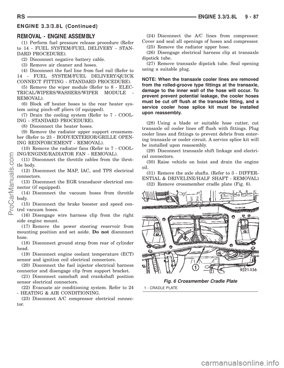
(32) Remove crossmember cradle plate (Fig. 6).
Fig. 6 Crossmember Cradle Plate
1 - CRADLE PLATE
RSENGINE 3.3/3.8L9-87
ENGINE 3.3/3.8L (Continued)
ProCarManuals.com
Page 1292 of 2399
(20) Install the powertrain struts (Fig. 8).
(21) Install the engine rear mount bracket.
(22) Install the engine front mount and bracket
assembly.
(23)AWD equipped;Install the power transfer
unit (PTU) (Refer to 21 - TRANSMISSION/TRANS-
AXLE/POWER TRANSFER UNIT - INSTALLA-
TION).
(24) Install the axle shafts (Refer to 3 - DIFFER-
ENTIAL & DRIVELINE/HALF SHAFT - INSTALLA-
TION).(25) Connect exhaust pipe to manifold (Fig. 7).
(26) Install crossmember cradle plate (Fig. 6).
(27) Lower vehicle.
(28) Connect transaxle shift linkage.
(29) Connect transaxle electrical connectors.
(30) Remove plugs from transmission cooler hoses
and install transaxle oil cooler line service splice kit.
Refer to instructions included with kit.
(31) Install transaxle dipstick tube and attach
electrical harness clip.
(32) Connect the A/C lines to compressor.
(33)
Connect the A/C compressor electrical connector.
(34) Evacuate and recharge A/C system.
(35) Connect crankshaft and camshaft position
sensors.
(36) Connect the fuel injector electrical harness
connector and engage clip to support bracket.
(37) Connect engine coolant temperature (ECT)
sensor and ignition coil electrical connectors.
(38) Connect the ground strap to rear of cylinder
head.
(39) Install power steering reservoir.
(40) Engage wire harness clip to engine right side
mount.
(41) Connect the brake booster and speed control
vacuum hoses.
(42) Connect the vacuum hoses to the throttle
body.
(43) Connect the EGR transducer electrical connec-
tor (if equipped).
(44) Connect the TPS, IAC, and MAP sensor elec-
trical connectors.
(45) Connect throttle cables to throttle body.
(46) Install the radiator fans (Refer to 7 - COOL-
ING/ENGINE/RADIATOR FAN - INSTALLATION).
(47) Connect the radiator upper hose.
(48) Connect the heater hoses. Remove pinch-off
pliers from the rear heater hoses (if equipped).
(49) Install the radiator upper support crossmem-
ber (Refer to 23 - BODY/EXTERIOR/GRILLE OPEN-
ING REINFORCEMENT - INSTALLATION).
(50) Install the wiper module (Refer to 8 - ELEC-
TRICAL/WIPERS/WASHERS/WIPER MODULE -
INSTALLATION).
(51) Connect the fuel line to fuel rail (Refer to 14 -
FUEL SYSTEM/FUEL DELIVERY/FUEL LINES -
STANDARD PROCEDURE).
(52) Install the air cleaner and hoses.
(53) Install new oil filter. Fill engine crankcase
with proper oil to correct level.
(54) Connect negative cable to battery.
(55) Fill the cooling system (Refer to 7 - COOLING
- STANDARD PROCEDURE).
(56) Start engine and run until operating temper-
ature is reached.
(57) Adjust transmission linkage, if necessary.
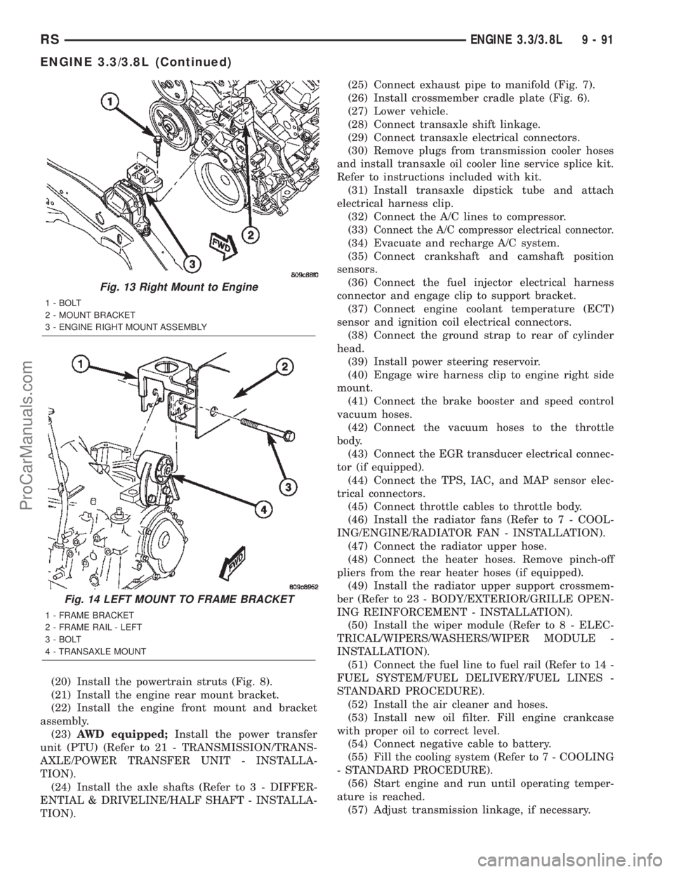
Fig. 13 Right Mount to Engine
1 - BOLT
2 - MOUNT BRACKET
3 - ENGINE RIGHT MOUNT ASSEMBLY
Fig. 14 LEFT MOUNT TO FRAME BRACKET
1 - FRAME BRACKET
2 - FRAME RAIL - LEFT
3 - BOLT
4 - TRANSAXLE MOUNT
RSENGINE 3.3/3.8L9-91
ENGINE 3.3/3.8L (Continued)
ProCarManuals.com
Page 1365 of 2399
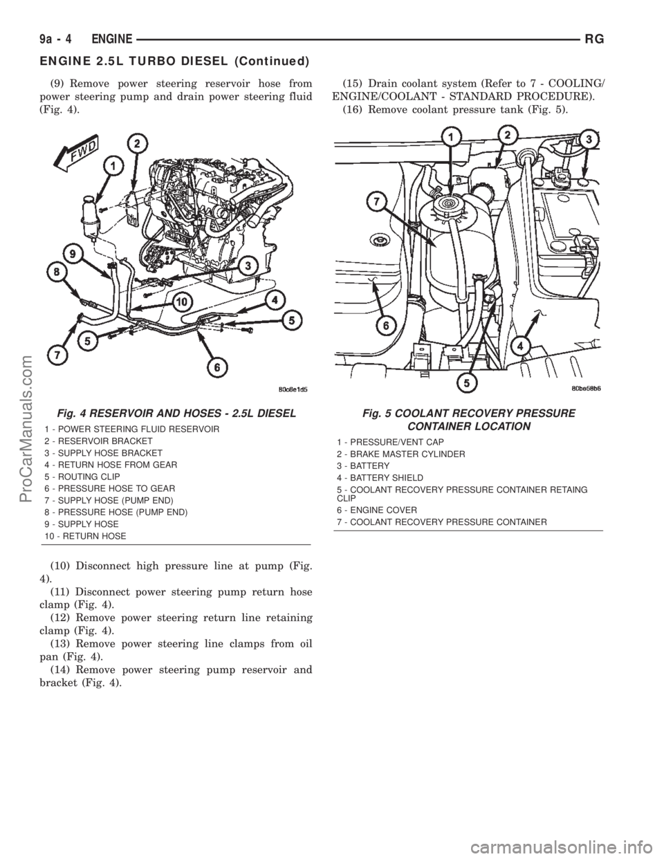
(9) Remove power steering reservoir hose from
power steering pump and drain power steering fluid
(Fig. 4).
(10) Disconnect high pressure line at pump (Fig.
4).
(11) Disconnect power steering pump return hose
clamp (Fig. 4).
(12) Remove power steering return line retaining
clamp (Fig. 4).
(13) Remove power steering line clamps from oil
pan (Fig. 4).
(14) Remove power steering pump reservoir and
bracket (Fig. 4).(15) Drain coolant system (Refer to 7 - COOLING/
ENGINE/COOLANT - STANDARD PROCEDURE).
(16) Remove coolant pressure tank (Fig. 5).
Fig. 4 RESERVOIR AND HOSES - 2.5L DIESEL
1 - POWER STEERING FLUID RESERVOIR
2 - RESERVOIR BRACKET
3 - SUPPLY HOSE BRACKET
4 - RETURN HOSE FROM GEAR
5 - ROUTING CLIP
6 - PRESSURE HOSE TO GEAR
7 - SUPPLY HOSE (PUMP END)
8 - PRESSURE HOSE (PUMP END)
9 - SUPPLY HOSE
10 - RETURN HOSE
Fig. 5 COOLANT RECOVERY PRESSURE
CONTAINER LOCATION
1 - PRESSURE/VENT CAP
2 - BRAKE MASTER CYLINDER
3 - BATTERY
4 - BATTERY SHIELD
5 - COOLANT RECOVERY PRESSURE CONTAINER RETAING
CLIP
6 - ENGINE COVER
7 - COOLANT RECOVERY PRESSURE CONTAINER
9a - 4 ENGINERG
ENGINE 2.5L TURBO DIESEL (Continued)
ProCarManuals.com