2002 CHRYSLER VOYAGER engine
[x] Cancel search: enginePage 1389 of 2399
(2) Remove front wiper unit (Refer to 8 - ELEC-
TRICAL/WIPERS/WASHERS/WIPER MODULE -
REMOVAL).
(3) Remove air cleaner housing assembly.
(4) Support engine and remove right engine mount
(Refer to 9 - ENGINE/ENGINE MOUNTING/RIGHT
MOUNT - REMOVAL).
(5) Remove outer timing belt cover (Refer to 9 -
ENGINE/VALVE TIMING/TIMING BELT / CHAIN
COVER(S) - REMOVAL).
(6) Remove timing belt (Refer to 9 - ENGINE/
VALVE TIMING/TIMING BELT/CHAIN AND
SPROCKETS - REMOVAL).
(7) Remove inner timing belt cover (Refer to 9 -
ENGINE/VALVE TIMING/TIMING BELT / CHAIN
COVER(S) - REMOVAL).
(8) Remove cylinder head cover/intake manifold
(Refer to 9 - ENGINE/CYLINDER HEAD/CYLIN-
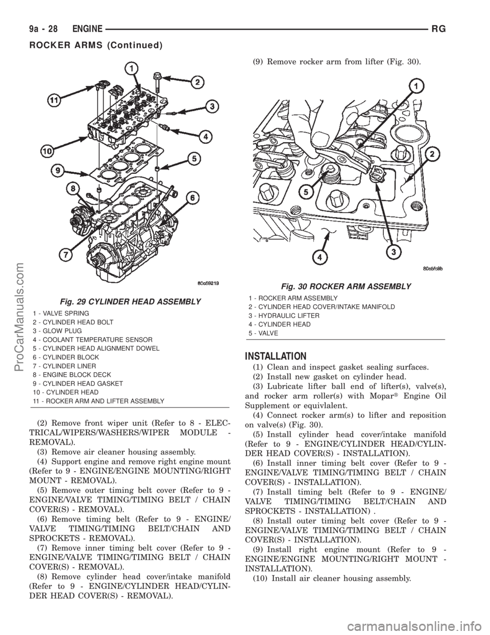
DER HEAD COVER(S) - REMOVAL).(9) Remove rocker arm from lifter (Fig. 30).
INSTALLATION
(1) Clean and inspect gasket sealing surfaces.
(2) Install new gasket on cylinder head.
(3) Lubricate lifter ball end of lifter(s), valve(s),
and rocker arm roller(s) with MopartEngine Oil
Supplement or equivlalent.
(4) Connect rocker arm(s) to lifter and reposition
on valve(s) (Fig. 30).
(5) Install cylinder head cover/intake manifold
(Refer to 9 - ENGINE/CYLINDER HEAD/CYLIN-
DER HEAD COVER(S) - INSTALLATION).
(6) Install inner timing belt cover (Refer to 9 -
ENGINE/VALVE TIMING/TIMING BELT / CHAIN
COVER(S) - INSTALLATION).
(7) Install timing belt (Refer to 9 - ENGINE/
VALVE TIMING/TIMING BELT/CHAIN AND
SPROCKETS - INSTALLATION) .
(8) Install outer timing belt cover (Refer to 9 -
ENGINE/VALVE TIMING/TIMING BELT / CHAIN
COVER(S) - INSTALLATION).
(9) Install right engine mount (Refer to 9 -
ENGINE/ENGINE MOUNTING/RIGHT MOUNT -
INSTALLATION).
(10) Install air cleaner housing assembly.
Fig. 29 CYLINDER HEAD ASSEMBLY
1 - VALVE SPRING
2 - CYLINDER HEAD BOLT
3 - GLOW PLUG
4 - COOLANT TEMPERATURE SENSOR
5 - CYLINDER HEAD ALIGNMENT DOWEL
6 - CYLINDER BLOCK
7 - CYLINDER LINER
8 - ENGINE BLOCK DECK
9 - CYLINDER HEAD GASKET
10 - CYLINDER HEAD
11 - ROCKER ARM AND LIFTER ASSEMBLY
Fig. 30 ROCKER ARM ASSEMBLY
1 - ROCKER ARM ASSEMBLY
2 - CYLINDER HEAD COVER/INTAKE MANIFOLD
3 - HYDRAULIC LIFTER
4 - CYLINDER HEAD
5 - VALVE
9a - 28 ENGINERG
ROCKER ARMS (Continued)
ProCarManuals.com
Page 1390 of 2399
(11) Install front wiper unit (Refer to 8 - ELEC-
TRICAL/WIPERS/WASHERS/WIPER MODULE -
INSTALLATION).
(12) Connect negative battery cable.
HYDRAULIC LIFTERS
DESCRIPTION
Valve lash is controlled by hydraulic tappets
located inside the cylinder head, in tappet bores
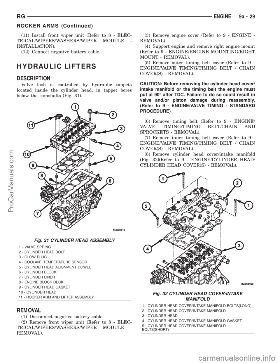
below the camshafts (Fig. 31).
REMOVAL
(1) Disconnect negative battery cable.
(2) Remove front wiper unit (Refer to 8 - ELEC-
TRICAL/WIPERS/WASHERS/WIPER MODULE -
REMOVAL).(3) Remove engine cover (Refer to 9 - ENGINE -
REMOVAL).
(4) Support engine and remove right engine mount
(Refer to 9 - ENGINE/ENGINE MOUNTING/RIGHT
MOUNT - REMOVAL).
(5) Remove outer timing belt cover (Refer to 9 -
ENGINE/VALVE TIMING/TIMING BELT / CHAIN
COVER(S) - REMOVAL).
CAUTION: Before removing the cylinder head cover/
intake manifold or the timing belt the engine must
put at 90É after TDC. Failure to do so could result in
valve and/or piston damage during reassembly.
(Refer to 9 - ENGINE/VALVE TIMING - STANDARD
PROCEDURE)
(6) Remove timing belt (Refer to 9 - ENGINE/
VALVE TIMING/TIMING BELT/CHAIN AND
SPROCKETS - REMOVAL).
(7) Remove inner timing belt cover (Refer to 9 -
ENGINE/VALVE TIMING/TIMING BELT / CHAIN
COVER(S) - REMOVAL).
(8) Remove cylinder head cover/intake manifold
(Fig. 32)(Refer to 9 - ENGINE/CYLINDER HEAD/
CYLINDER HEAD COVER(S) - REMOVAL).
Fig. 31 CYLINDER HEAD ASSEMBLY
1 - VALVE SPRING
2 - CYLINDER HEAD BOLT
3 - GLOW PLUG
4 - COOLANT TEMPERATURE SENSOR
5 - CYLINDER HEAD ALIGNMENT DOWEL
6 - CYLINDER BLOCK
7 - CYLINDER LINER
8 - ENGINE BLOCK DECK
9 - CYLINDER HEAD GASKET
10 - CYLINDER HEAD
11 - ROCKER ARM AND LIFTER ASSEMBLY
Fig. 32 CYLINDER HEAD COVER/INTAKE
MANIFOLD
1 - CYLINDER HEAD COVER/INTAKE MANIFOLD BOLTS(LONG)
2 - CYLINDER HEAD COVER/INTAKE MANIFOLD
3 - CYLINDER HEAD
4 - CYLINDER HEAD COVER/INTAKE MANIFOLD GASKET
5 - CYLINDER HEAD COVER/INTAKE MANIFOLD
BOLTS(SHORT)
RGENGINE9a-29
ROCKER ARMS (Continued)
ProCarManuals.com
Page 1391 of 2399
(9) Remove rocker arm and lifter assemblies from
lifter bores.
INSPECTION
Clean each lifter assembly in cleaning solvent to
remove all varnish and sludge deposits. Inspect for
indications of scuffing on the side and base of each
lifter body.
INSTALLATION
(1) Install rocker arm and lifter assemblies in
lifter bores.
(2) Install cylinder head cover/intake manifold
(Fig. 32) (Refer to 9 - ENGINE/CYLINDER HEAD/
CYLINDER HEAD COVER(S) - INSTALLATION).
(3) Install timing belt inner cover (Refer to 9 -
ENGINE/VALVE TIMING/TIMING BELT / CHAIN
COVER(S) - INSTALLATION).
(4) Install timing belt (Refer to 9 - ENGINE/
VALVE TIMING/TIMING BELT/CHAIN AND
SPROCKETS - INSTALLATION) .
(5) Install timing belt outer cover (Refer to 9 -
ENGINE/VALVE TIMING/TIMING BELT / CHAIN
COVER(S) - INSTALLATION).
(6) Install right engine mount (Refer to 9 -
ENGINE/ENGINE MOUNTING/RIGHT MOUNT -
INSTALLATION).
(7) Install engine cover (Refer to 9 - ENGINE -
INSTALLATION).
(8) Install front wiper unit (Refer to 8 - ELECTRI-
CAL/WIPERS/WASHERS/WIPER MODULE -
INSTALLATION).
(9) Connect negative battery cable.
ENGINE BLOCK
DESCRIPTION
The 2.5L CRD Diesel engine uses a cast iron
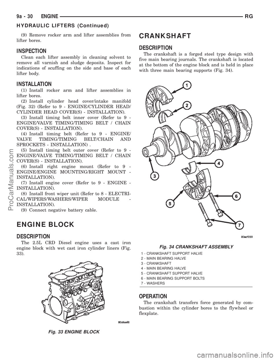
engine block with wet cast iron cylinder liners (Fig.
33).
CRANKSHAFT
DESCRIPTION
The crankshaft is a forged steel type design with
five main bearing journals. The crankshaft is located
at the bottom of the engine block and is held in place
with three main bearing supports (Fig. 34).
OPERATION
The crankshaft transfers force generated by com-
bustion within the cylinder bores to the flywheel or
flexplate.
Fig. 33 ENGINE BLOCK
Fig. 34 CRANKSHAFT ASSEMBLY
1 - CRANKSHAFT SUPPORT HALVE
2 - MAIN BEARING HALVE
3 - CRANKSHAFT
4 - MAIN BEARING HALVE
5 - CRANKSHAFT SUPPORT HALVE
6 - MAIN BEARING SUPPORT BOLTS
7 - WASHERS
9a - 30 ENGINERG
HYDRAULIC LIFTERS (Continued)
ProCarManuals.com
Page 1392 of 2399
STANDARD PROCEDURE - CHECKING
CRANKSHAFT END PLAY
(1) Mount a dial indicator to a stationary point at
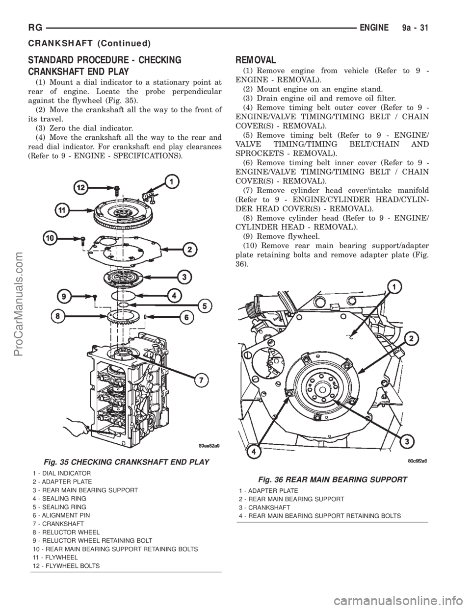
rear of engine. Locate the probe perpendicular
against the flywheel (Fig. 35).
(2) Move the crankshaft all the way to the front of
its travel.
(3) Zero the dial indicator.
(4)
Move the crankshaft all the way to the rear and
read dial indicator. For crankshaft end play clearances
(Refer to 9 - ENGINE - SPECIFICATIONS).
REMOVAL
(1) Remove engine from vehicle (Refer to 9 -
ENGINE - REMOVAL).
(2) Mount engine on an engine stand.
(3) Drain engine oil and remove oil filter.
(4) Remove timing belt outer cover (Refer to 9 -
ENGINE/VALVE TIMING/TIMING BELT / CHAIN
COVER(S) - REMOVAL).
(5) Remove timing belt (Refer to 9 - ENGINE/
VALVE TIMING/TIMING BELT/CHAIN AND
SPROCKETS - REMOVAL).
(6) Remove timing belt inner cover (Refer to 9 -
ENGINE/VALVE TIMING/TIMING BELT / CHAIN
COVER(S) - REMOVAL).
(7) Remove cylinder head cover/intake manifold
(Refer to 9 - ENGINE/CYLINDER HEAD/CYLIN-
DER HEAD COVER(S) - REMOVAL).
(8) Remove cylinder head (Refer to 9 - ENGINE/
CYLINDER HEAD - REMOVAL).
(9) Remove flywheel.
(10) Remove rear main bearing support/adapter
plate retaining bolts and remove adapter plate (Fig.
36).
Fig. 35 CHECKING CRANKSHAFT END PLAY
1 - DIAL INDICATOR
2 - ADAPTER PLATE
3 - REAR MAIN BEARING SUPPORT
4 - SEALING RING
5 - SEALING RING
6 - ALIGNMENT PIN
7 - CRANKSHAFT
8 - RELUCTOR WHEEL
9 - RELUCTOR WHEEL RETAINING BOLT
10 - REAR MAIN BEARING SUPPORT RETAINING BOLTS
11 - FLYWHEEL
12 - FLYWHEEL BOLTSFig. 36 REAR MAIN BEARING SUPPORT
1 - ADAPTER PLATE
2 - REAR MAIN BEARING SUPPORT
3 - CRANKSHAFT
4 - REAR MAIN BEARING SUPPORT RETAINING BOLTS
RGENGINE9a-31
CRANKSHAFT (Continued)
ProCarManuals.com
Page 1393 of 2399
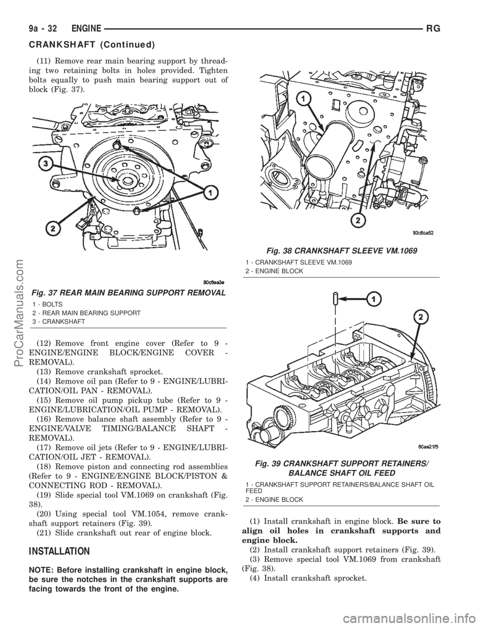
(11) Remove rear main bearing support by thread-
ing two retaining bolts in holes provided. Tighten
bolts equally to push main bearing support out of
block (Fig. 37).
(12) Remove front engine cover (Refer to 9 -
ENGINE/ENGINE BLOCK/ENGINE COVER -
REMOVAL).
(13) Remove crankshaft sprocket.
(14) Remove oil pan (Refer to 9 - ENGINE/LUBRI-
CATION/OIL PAN - REMOVAL).
(15) Remove oil pump pickup tube (Refer to 9 -
ENGINE/LUBRICATION/OIL PUMP - REMOVAL).
(16) Remove balance shaft assembly (Refer to 9 -
ENGINE/VALVE TIMING/BALANCE SHAFT -
REMOVAL).
(17) Remove oil jets (Refer to 9 - ENGINE/LUBRI-
CATION/OIL JET - REMOVAL).
(18) Remove piston and connecting rod assemblies
(Refer to 9 - ENGINE/ENGINE BLOCK/PISTON &
CONNECTING ROD - REMOVAL).
(19) Slide special tool VM.1069 on crankshaft (Fig.
38).
(20) Using special tool VM.1054, remove crank-
shaft support retainers (Fig. 39).
(21) Slide crankshaft out rear of engine block.
INSTALLATION
NOTE: Before installing crankshaft in engine block,
be sure the notches in the crankshaft supports are
facing towards the front of the engine.(1) Install crankshaft in engine block.Be sure to
align oil holes in crankshaft supports and
engine block.
(2) Install crankshaft support retainers (Fig. 39).
(3) Remove special tool VM.1069 from crankshaft
(Fig. 38).
(4) Install crankshaft sprocket.
Fig. 37 REAR MAIN BEARING SUPPORT REMOVAL
1 - BOLTS
2 - REAR MAIN BEARING SUPPORT
3 - CRANKSHAFT
Fig. 38 CRANKSHAFT SLEEVE VM.1069
1 - CRANKSHAFT SLEEVE VM.1069
2 - ENGINE BLOCK
Fig. 39 CRANKSHAFT SUPPORT RETAINERS/
BALANCE SHAFT OIL FEED
1 - CRANKSHAFT SUPPORT RETAINERS/BALANCE SHAFT OIL
FEED
2 - ENGINE BLOCK
9a - 32 ENGINERG
CRANKSHAFT (Continued)
ProCarManuals.com
Page 1394 of 2399
(5) Install front engine cover (Refer to 9 -
ENGINE/ENGINE BLOCK/ENGINE COVER -
INSTALLATION).
(6) Install rear main bearing support in engine
block.Be sure to align oil hole in rear main
bearing support with hole in block.
(7) Install adapter plate and retaining bolts (Fig.
36). Torque bolts to 27.5N´m.
(8) Install flywheel.
(9) Install piston and connecting rod assemblies
(Refer to 9 - ENGINE/ENGINE BLOCK/PISTON &
CONNECTING ROD - INSTALLATION).
(10) Install oil jets (Refer to 9 - ENGINE/LUBRI-
CATION/OIL JET - INSTALLATION).
(11) Install balance shaft assembly (Refer to 9 -
ENGINE/VALVE TIMING/BALANCE SHAFT -
INSTALLATION).
(12)
Install oil pump pickup tube (Refer to 9 -
ENGINE/LUBRICATION/OIL PUMP - INSTALLATION).
(13) Install oil pan (Refer to 9 - ENGINE/LUBRI-
CATION/OIL PAN - INSTALLATION).
(14) Install cylinder head (Refer to 9 - ENGINE/
CYLINDER HEAD - INSTALLATION).
(15) Install cylinder head cover/intake manifold
(Refer to 9 - ENGINE/CYLINDER HEAD/CYLIN-
DER HEAD COVER(S) - INSTALLATION).
(16) Install timing belt inner cover (Refer to 9 -
ENGINE/VALVE TIMING/TIMING BELT / CHAIN
COVER(S) - INSTALLATION).
(17) Install timing belt (Refer to 9 - ENGINE/
VALVE TIMING/TIMING BELT/CHAIN AND
SPROCKETS - INSTALLATION) .
(18) Install timing belt outer cover (Refer to 9 -
ENGINE/VALVE TIMING/TIMING BELT / CHAIN
COVER(S) - INSTALLATION).
(19) Install engine in vehicle.
(20) Fill engine oil with proper oil to correct level.
CYLINDER LINERS
DESCRIPTION
The cylinder wall liner used on this engine is of
the wet design. O-rings are used to seal the liner to
the engine block.
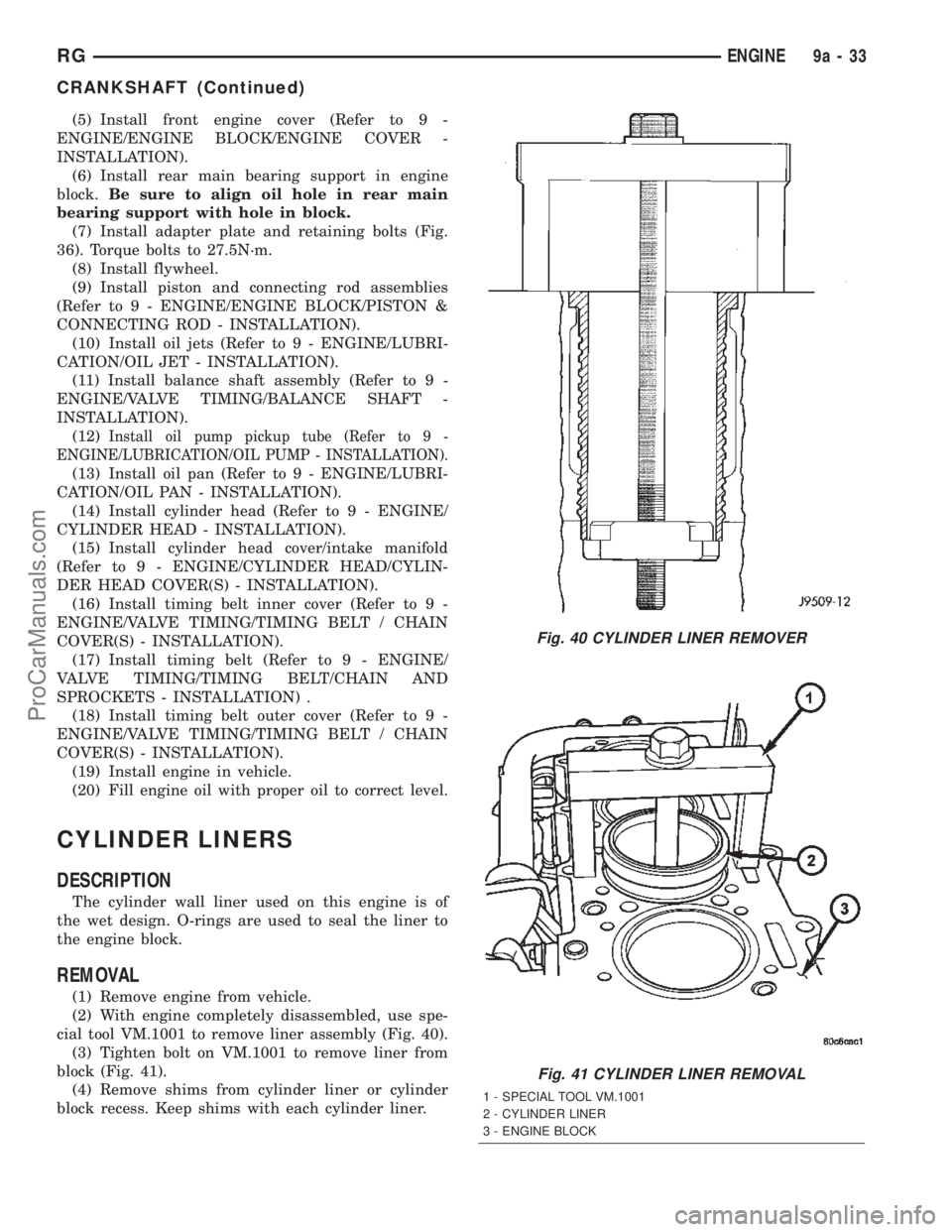
REMOVAL
(1) Remove engine from vehicle.
(2) With engine completely disassembled, use spe-
cial tool VM.1001 to remove liner assembly (Fig. 40).
(3) Tighten bolt on VM.1001 to remove liner from
block (Fig. 41).
(4) Remove shims from cylinder liner or cylinder
block recess. Keep shims with each cylinder liner.
Fig. 40 CYLINDER LINER REMOVER
Fig. 41 CYLINDER LINER REMOVAL
1 - SPECIAL TOOL VM.1001
2 - CYLINDER LINER
3 - ENGINE BLOCK
RGENGINE9a-33
CRANKSHAFT (Continued)
ProCarManuals.com
Page 1395 of 2399
INSPECTION
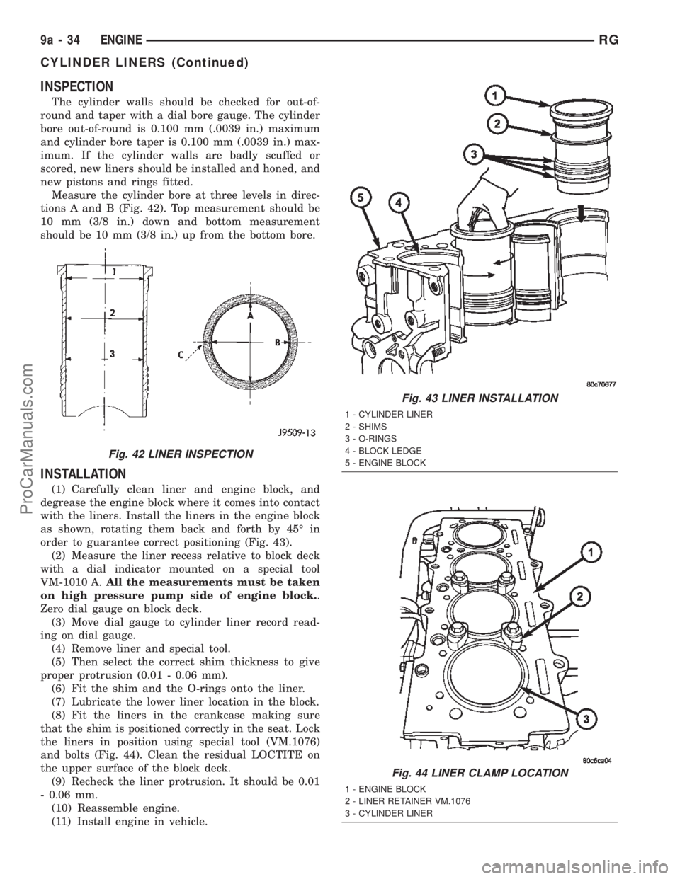
The cylinder walls should be checked for out-of-
round and taper with a dial bore gauge. The cylinder
bore out-of-round is 0.100 mm (.0039 in.) maximum
and cylinder bore taper is 0.100 mm (.0039 in.) max-
imum. If the cylinder walls are badly scuffed or
scored, new liners should be installed and honed, and
new pistons and rings fitted.
Measure the cylinder bore at three levels in direc-
tions A and B (Fig. 42). Top measurement should be
10 mm (3/8 in.) down and bottom measurement
should be 10 mm (3/8 in.) up from the bottom bore.
INSTALLATION
(1) Carefully clean liner and engine block, and
degrease the engine block where it comes into contact
with the liners. Install the liners in the engine block
as shown, rotating them back and forth by 45É in
order to guarantee correct positioning (Fig. 43).
(2) Measure the liner recess relative to block deck
with a dial indicator mounted on a special tool
VM-1010 A.All the measurements must be taken
on high pressure pump side of engine block..
Zero dial gauge on block deck.
(3) Move dial gauge to cylinder liner record read-
ing on dial gauge.
(4) Remove liner and special tool.
(5) Then select the correct shim thickness to give
proper protrusion (0.01 - 0.06 mm).
(6) Fit the shim and the O-rings onto the liner.
(7) Lubricate the lower liner location in the block.
(8) Fit the liners in the crankcase making sure
that the shim is positioned correctly in the seat. Lock
the liners in position using special tool (VM.1076)
and bolts (Fig. 44). Clean the residual LOCTITE on
the upper surface of the block deck.
(9) Recheck the liner protrusion. It should be 0.01
- 0.06 mm.
(10) Reassemble engine.
(11) Install engine in vehicle.
Fig. 42 LINER INSPECTION
Fig. 43 LINER INSTALLATION
1 - CYLINDER LINER
2 - SHIMS
3 - O-RINGS
4 - BLOCK LEDGE
5 - ENGINE BLOCK
Fig. 44 LINER CLAMP LOCATION
1 - ENGINE BLOCK
2 - LINER RETAINER VM.1076
3 - CYLINDER LINER
9a - 34 ENGINERG
CYLINDER LINERS (Continued)
ProCarManuals.com
Page 1396 of 2399
INTERNAL VACUUM PUMP
DESCRIPTION
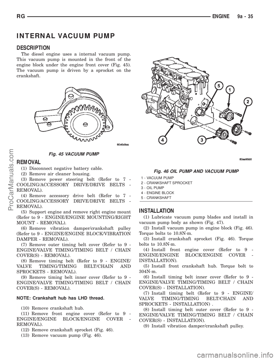
The diesel engine uses a internal vacuum pump.
This vacuum pump is mounted in the front of the
engine block under the engine front cover (Fig. 45).
The vacuum pump is driven by a sprocket on the
crankshaft.
REMOVAL
(1) Disconnect negative battery cable.
(2) Remove air cleaner housing.
(3) Remove power steering belt (Refer to 7 -
COOLING/ACCESSORY DRIVE/DRIVE BELTS -
REMOVAL).
(4) Remove accessory drive belt (Refer to 7 -
COOLING/ACCESSORY DRIVE/DRIVE BELTS -
REMOVAL).
(5) Support engine and remove right engine mount
(Refer to 9 - ENGINE/ENGINE MOUNTING/RIGHT
MOUNT - REMOVAL).
(6) Remove vibration damper/crankshaft pulley
(Refer to 9 - ENGINE/ENGINE BLOCK/VIBRATION
DAMPER - REMOVAL).
(7) Remove outer timing belt cover (Refer to 9 -
ENGINE/VALVE TIMING/TIMING BELT / CHAIN
COVER(S) - REMOVAL).
(8) Remove timing belt (Refer to 9 - ENGINE/
VALVE TIMING/TIMING BELT/CHAIN AND
SPROCKETS - REMOVAL).
(9) Remove timing belt inner cover (Refer to 9 -
ENGINE/VALVE TIMING/TIMING BELT / CHAIN
COVER(S) - REMOVAL).
NOTE: Crankshaft hub has LHD thread.
(10) Remove crankshaft hub.
(11) Remove front engine cover (Refer to 9 -
ENGINE/ENGINE BLOCK/ENGINE COVER -
REMOVAL).
(12) Remove crankshaft sprocket (Fig. 46).
(13) Remove vacuum pump (Fig. 46).
INSTALLATION
(1) Lubricate vacuum pump blades and install in
vacuum pump body as shown (Fig. 47).
(2) Install vacuum pump in engine block (Fig. 46).
Torque bolts to 10.8N´m.
(3) Install crankshaft sprocket (Fig. 46). Torque
bolts to 10.8N´m.
(4) Install front engine cover (Refer to 9 -
ENGINE/ENGINE BLOCK/ENGINE COVER -
INSTALLATION).
(5) Install front crankshaft hub. Torque bolt to
304N´m.
(6) Install timing belt inner cover (Refer to 9 -
ENGINE/VALVE TIMING/TIMING BELT / CHAIN
COVER(S) - INSTALLATION).
(7) Install timing belt (Refer to 9 - ENGINE/
VALVE TIMING/TIMING BELT/CHAIN AND
SPROCKETS - INSTALLATION) .
(8) Install timing belt outer cover (Refer to 9 -
ENGINE/VALVE TIMING/TIMING BELT / CHAIN
COVER(S) - INSTALLATION).
(9) Install vibration damper/crankshaft pulley.
Fig. 45 VACUUM PUMP
Fig. 46 OIL PUMP AND VACUUM PUMP
1 - VACUUM PUMP
2 - CRANKSHAFT SPROCKET
3 - OIL PUMP
4 - ENGINE BLOCK
5 - CRANKSHAFT
RGENGINE9a-35
ProCarManuals.com