Page 1902 of 2399
SPECIAL TOOLS - T850 TRANSAXLE
Bearing Splitter, P-334
Slide Hammer, C-3752
Universal Handle, C-4171
Torque Tool, C-4995
Puller Set, 5048
Disconnect Tool, 6638A
Remover, 6786
RST850 MANUAL TRANSAXLE21 - 345
T850 MANUAL TRANSAXLE (Continued)
ProCarManuals.com
Page 1906 of 2399
BACK-UP LAMP SWITCH
REMOVAL
(1) Raise vehicle on hoist.
(2) Disconnect back-up lamp switch connector.
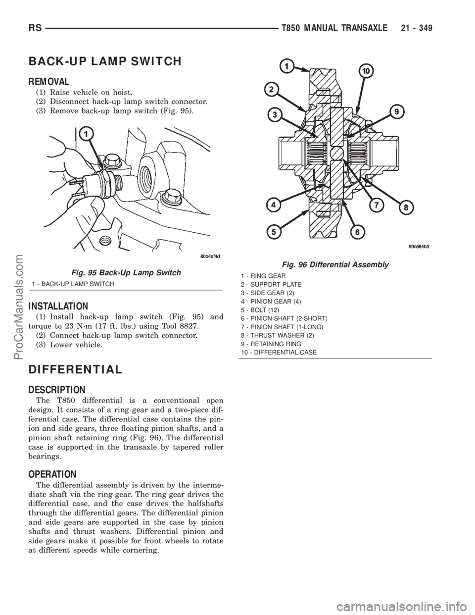
(3) Remove back-up lamp switch (Fig. 95).
INSTALLATION
(1) Install back-up lamp switch (Fig. 95) and
torque to 23 N´m (17 ft. lbs.) using Tool 8827.
(2) Connect back-up lamp switch connector.
(3) Lower vehicle.
DIFFERENTIAL
DESCRIPTION
The T850 differential is a conventional open
design. It consists of a ring gear and a two-piece dif-
ferential case. The differential case contains the pin-
ion and side gears, three floating pinion shafts, and a
pinion shaft retaining ring (Fig. 96). The differential
case is supported in the transaxle by tapered roller
bearings.
OPERATION
The differential assembly is driven by the interme-
diate shaft via the ring gear. The ring gear drives the
differential case, and the case drives the halfshafts
through the differential gears. The differential pinion
and side gears are supported in the case by pinion
shafts and thrust washers. Differential pinion and
side gears make it possible for front wheels to rotate
at different speeds while cornering.
Fig. 95 Back-Up Lamp Switch
1 - BACK-UP LAMP SWITCH
Fig. 96 Differential Assembly
1 - RING GEAR
2 - SUPPORT PLATE
3 - SIDE GEAR (2)
4 - PINION GEAR (4)
5 - BOLT (12)
6 - PINION SHAFT (2-SHORT)
7 - PINION SHAFT (1-LONG)
8 - THRUST WASHER (2)
9 - RETAINING RING
10 - DIFFERENTIAL CASE
RST850 MANUAL TRANSAXLE21 - 349
ProCarManuals.com
Page 1912 of 2399
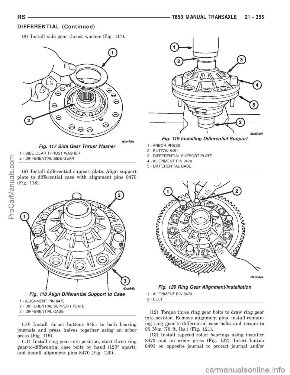
(8) Install side gear thrust washer (Fig. 117).
(9) Install differential support plate. Align support
plate to differential case with alignment pins 8470
(Fig. 118).
(10) Install thrust buttons 8491 to both bearing
journals and press halves together using an arbor
press (Fig. 119).
(11) Install ring gear into position, start three ring
gear-to-differential case bolts by hand (120É apart),
and install alignment pins 8470 (Fig. 120).(12) Torque three ring gear bolts to draw ring gear
into position. Remove alignment pins, install remain-
ing ring gear-to-differential case bolts and torque to
95 N´m (70 ft. lbs.) (Fig. 121).
(13) Install tapered roller bearings using installer
8473 and an arbor press (Fig. 122). Insert button
8491 on opposite journal to protect journal and/or
Fig. 117 Side Gear Thrust Washer
1 - SIDE GEAR THRUST WASHER
2 - DIFFERENTIAL SIDE GEAR
Fig. 118 Align Differential Support to Case
1 - ALIGNMENT PIN 8470
2 - DIFFERENTIAL SUPPORT PLATE
3 - DIFFERENTIAL CASE
Fig. 119 Installing Differential Support
1 - ARBOR PRESS
2 - BUTTON 8491
3 - DIFFERENTIAL SUPPORT PLATE
4 - ALIGNMENT PIN 8470
5 - DIFFERENTIAL CASE
Fig. 120 Ring Gear Alignment/Installation
1 - ALIGNMENT PIN 8470
2 - BOLT
RST850 MANUAL TRANSAXLE21 - 355
DIFFERENTIAL (Continued)
ProCarManuals.com
Page 1913 of 2399
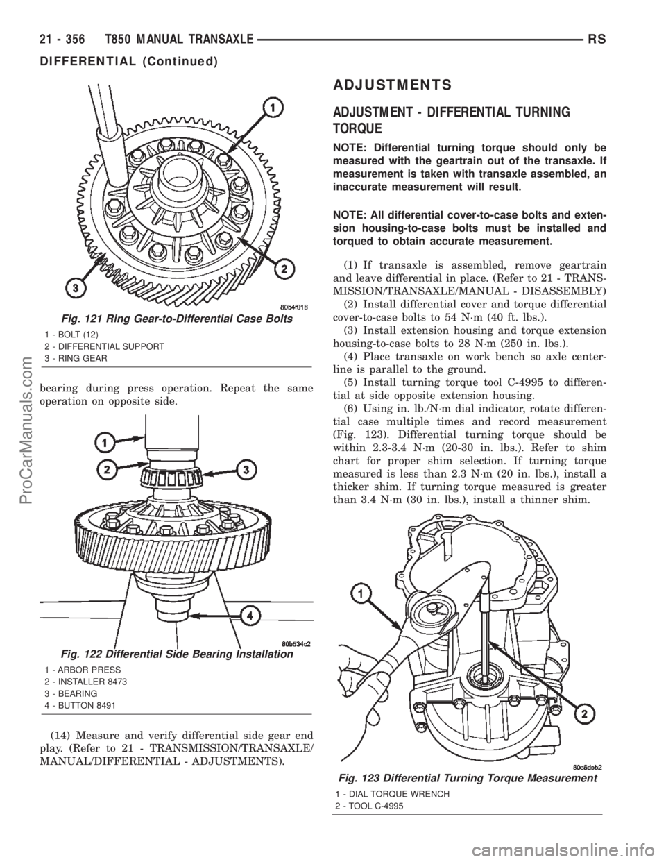
bearing during press operation. Repeat the same
operation on opposite side.
(14) Measure and verify differential side gear end
play. (Refer to 21 - TRANSMISSION/TRANSAXLE/
MANUAL/DIFFERENTIAL - ADJUSTMENTS).
ADJUSTMENTS
ADJUSTMENT - DIFFERENTIAL TURNING
TORQUE
NOTE: Differential turning torque should only be
measured with the geartrain out of the transaxle. If
measurement is taken with transaxle assembled, an
inaccurate measurement will result.
NOTE: All differential cover-to-case bolts and exten-
sion housing-to-case bolts must be installed and
torqued to obtain accurate measurement.
(1) If transaxle is assembled, remove geartrain
and leave differential in place. (Refer to 21 - TRANS-
MISSION/TRANSAXLE/MANUAL - DISASSEMBLY)
(2) Install differential cover and torque differential
cover-to-case bolts to 54 N´m (40 ft. lbs.).
(3) Install extension housing and torque extension
housing-to-case bolts to 28 N´m (250 in. lbs.).
(4) Place transaxle on work bench so axle center-
line is parallel to the ground.
(5) Install turning torque tool C-4995 to differen-
tial at side opposite extension housing.
(6) Using in. lb./N´m dial indicator, rotate differen-
tial case multiple times and record measurement
(Fig. 123). Differential turning torque should be
within 2.3-3.4 N´m (20-30 in. lbs.). Refer to shim
chart for proper shim selection. If turning torque
measured is less than 2.3 N´m (20 in. lbs.), install a
thicker shim. If turning torque measured is greater
than 3.4 N´m (30 in. lbs.), install a thinner shim.
Fig. 123 Differential Turning Torque Measurement
1 - DIAL TORQUE WRENCH
2 - TOOL C-4995
Fig. 121 Ring Gear-to-Differential Case Bolts
1 - BOLT (12)
2 - DIFFERENTIAL SUPPORT
3 - RING GEAR
Fig. 122 Differential Side Bearing Installation
1 - ARBOR PRESS
2 - INSTALLER 8473
3 - BEARING
4 - BUTTON 8491
21 - 356 T850 MANUAL TRANSAXLERS
DIFFERENTIAL (Continued)
ProCarManuals.com
Page 1916 of 2399
STANDARD PROCEDURE - FLUID DRAIN AND
FILL
NOTE: For proper fluid change intervals, (Refer to
LUBRICATION & MAINTENANCE/MAINTENANCE
SCHEDULES - DESCRIPTION)
The fluid required in this transaxle is Mopart
ATF+4 (Automatic Transmission FluidÐType 9602).
Use of substitute fluids may result in improper
transaxle operation and/or failure.
FLUID DRAIN
(1) Raise vehicle on hoist.
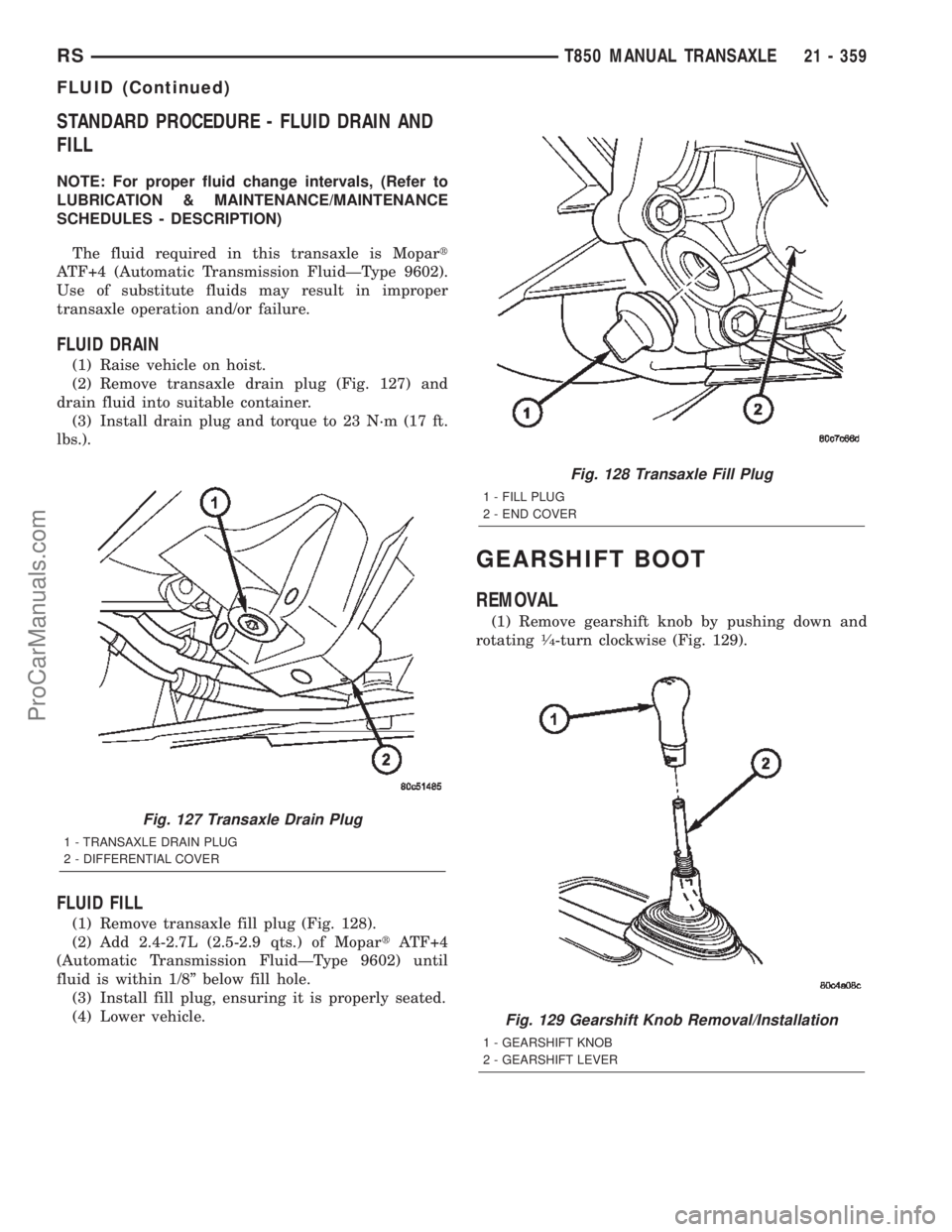
(2) Remove transaxle drain plug (Fig. 127) and
drain fluid into suitable container.
(3) Install drain plug and torque to 23 N´m (17 ft.
lbs.).
FLUID FILL
(1) Remove transaxle fill plug (Fig. 128).
(2) Add 2.4-2.7L (2.5-2.9 qts.) of MopartATF+4
(Automatic Transmission FluidÐType 9602) until
fluid is within 1/8º below fill hole.
(3) Install fill plug, ensuring it is properly seated.
(4) Lower vehicle.
GEARSHIFT BOOT
REMOVAL
(1) Remove gearshift knob by pushing down and
rotating1¤4-turn clockwise (Fig. 129).
Fig. 127 Transaxle Drain Plug
1 - TRANSAXLE DRAIN PLUG
2 - DIFFERENTIAL COVER
Fig. 128 Transaxle Fill Plug
1 - FILL PLUG
2 - END COVER
Fig. 129 Gearshift Knob Removal/Installation
1 - GEARSHIFT KNOB
2 - GEARSHIFT LEVER
RST850 MANUAL TRANSAXLE21 - 359
FLUID (Continued)
ProCarManuals.com
Page 1922 of 2399
(10) Install crossover cable to gearshift mechanism
(Fig. 148). Install retainer clip (Fig. 149).
(11) Adjust crossover cable (Refer to 21 - TRANS-
MISSION/TRANSAXLE/MANUAL/GEAR SHIFT
CABLE - ADJUSTMENTS).
(12) Install center console support bracket (Fig.
150). Torque support bracket-to-gearshift mechanism
screws to 12 N´m (108 in. lbs.).
(13) Install center console assembly (Fig. 151).
Install and torque center console-to-gearshift mecha-
nism screws to 5 N´m (45 in. lbs.).
Fig. 148 Crossover Cable at Gearshift Mechanism
1 - GEARSHIFT MECHANISM
2 - CROSSOVER CABLE
Fig. 149 Crossover Cable Retainer Clip
1 - RETAINER CLIP
2 - CROSSOVER CABLE
Fig. 150 Center Console Support Bracket
1 - BRACKET
2 - SCREW
3 - GEARSHIFT MECHANISM
Fig. 151 Center Console Removal/Installation (LHD
Shown Ð RHD Typical)
1 - CENTER CONSOLE
2 - SCREW (4)
3 - GEARSHIFT MECHANISM
RST850 MANUAL TRANSAXLE21 - 365
GEARSHIFT CABLE - CROSSOVER (Continued)
ProCarManuals.com
Page 1925 of 2399
(9) Torque crossover lever adjustment screw to 8
N´m (70 in. lbs.).No load should be applied to
the shifter lever in any direction (hands off)
while tightening screw.
(10) Verify gearshift lever travel through all gear
ranges with engine off (not running).
(11) Install center console assembly (Fig. 158).
Install and torque center console-to-gearshift mecha-
nism screws to 5 N´m (45 in. lbs.).
(12) Install cupholder plugs (Fig. 157).
(13) Install gearshift boot to console (Fig. 156).
Secure boot to console with three (3) retainer clips.
(14) Install gearshift knob to gearshift lever (Fig.
155). Orient shift pattern on knob
1¤4-turn clockwise,
push down and rotate1¤4-turn counter-clockwise and
release. Secure boot to knob.
(15) Connect battery negative cable.
GEARSHIFT CABLE -
SELECTOR
REMOVAL
(1) Disconnect battery negative cable.
(2) Remove gearshift knob by pushing down and
rotating
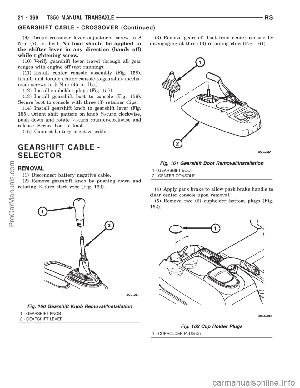
1¤4-turn clock-wise (Fig. 160).(3) Remove gearshift boot from center console by
disengaging at three (3) retaining clips (Fig. 161).
(4) Apply park brake to allow park brake handle to
clear center console upon removal.
(5) Remove two (2) cupholder bottom plugs (Fig.
162).
Fig. 160 Gearshift Knob Removal/Installation
1 - GEARSHIFT KNOB
2 - GEARSHIFT LEVER
Fig. 161 Gearshift Boot Removal/Installation
1 - GEARSHIFT BOOT
2 - CENTER CONSOLE
Fig. 162 Cup Holder Plugs
1 - CUPHOLDER PLUG (2)
21 - 368 T850 MANUAL TRANSAXLERS
GEARSHIFT CABLE - CROSSOVER (Continued)
ProCarManuals.com
Page 1930 of 2399
(11) Install center console support bracket (Fig.
179). Torque support bracket-to-gearshift mechanism
screws to 12 N´m (108 in. lbs.).(12) Install center console assembly (Fig. 180).
Install and torque center console-to-gearshift mecha-
nism screws to 5 N´m (45 in. lbs.).
(13) Install cupholder plugs (Fig. 181).
Fig. 178 Selector Cable Retainer Clip
1 - RETAINER CLIP
Fig. 179 Center Console Support Bracket
1 - BRACKET
2 - SCREW
3 - GEARSHIFT MECHANISM
Fig. 180 Center Console Removal/Installation (LHD
Shown Ð RHD Typical)
1 - CENTER CONSOLE
2 - SCREW (4)
3 - GEARSHIFT MECHANISM
Fig. 181 Cup Holder Plugs
1 - CUPHOLDER PLUG (2)
RST850 MANUAL TRANSAXLE21 - 373
GEARSHIFT CABLE - SELECTOR (Continued)
ProCarManuals.com