2002 CHRYSLER VOYAGER electric
[x] Cancel search: electricPage 2022 of 2399
DECKLID/HATCH/LIFTGATE/TAILGATE
TABLE OF CONTENTS
page page
EXTERIOR HANDLE
REMOVAL.............................39
INSTALLATION.........................39
HINGE
REMOVAL.............................39
INSTALLATION.........................39
LATCH
REMOVAL.............................40
INSTALLATION.........................40
LATCH STRIKER
REMOVAL.............................40
INSTALLATION.........................40
LIFTGATE
REMOVAL.............................40
INSTALLATION.........................41
LIFTGATE SPOILER
REMOVAL.............................41INSTALLATION.........................41
LOCK CYLINDER
REMOVAL.............................42
INSTALLATION.........................42
SUPPORT CYLINDER
REMOVAL.............................42
INSTALLATION.........................42
TRIM PANEL
REMOVAL.............................42
INSTALLATION.........................43
SLAM BUMPER
REMOVAL
REMOVAL...........................43
REMOVAL - LIFTGATE SIDE.............43
INSTALLATION
INSTALLATION.......................43
INSTALLATION - LIFTGATE SIDE.........43
EXTERIOR HANDLE
REMOVAL
(1) Remove liftgate trim panel. (Refer to 23 -
BODY/DECKLID/HATCH/LIFTGATE/TAILGATE/
TRIM PANEL - REMOVAL)
(2) Disconnect the exterior handle electrical con-
nectors.
(3) Remove the two outer screws and the two inner
screws.
(4) Remove the exterior handle/license plate light
assembly.
INSTALLATION
(1) Route the exterior handle electrical connector
through the door and position handle.
(2) Install the two out screws and tighten to 20
N´m (15 ft. lbs.).
(3) Install the two inner bolts and tighten to 40
N´m (30 ft. lbs.).
(4) Connect the electrical connector.
(5) Install the trim panel. (Refer to 23 - BODY/
DECKLID/HATCH/LIFTGATE/TAILGATE/TRIM
PANEL - INSTALLATION)
HINGE
REMOVAL
(1) Release liftgate latch and open liftgate.
(2) Support liftgate on a suitable lifting device in
the full open position.
(3) Apply several layers of duct tape on the outside
of to roof across the gap to the lift gate to hold the
liftgate in position.
(4) Remove bolts attaching liftgate hinge to roof
header.
(5) Disconnect VTSS switch from the body har-
ness.
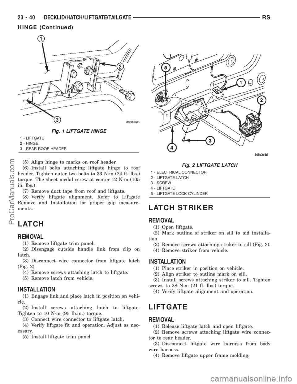
(6) Remove bolts attaching hinge to liftgate (Fig.
1).
(7) Remove hinge from vehicle.
INSTALLATION
(1) If necessary, paint replacement hinge before
installation.
(2) Place hinge in position on vehicle.
(3) Align hinge to marks on liftgate.
(4) Install bolts attaching hinge to liftgate (Fig. 1)
. Tighten bolts to 33 N´m (24 ft. lbs.) torque.
RSDECKLID/HATCH/LIFTGATE/TAILGATE23-39
ProCarManuals.com
Page 2023 of 2399
(5) Align hinge to marks on roof header.
(6) Install bolts attaching liftgate hinge to roof
header. Tighten outer two bolts to 33 N´m (24 ft. lbs.)
torque. The sheet medal screw at center 12 N´m (105
in. lbs.)
(7) Remove duct tape from roof and liftgate.
(8) Verify liftgate alignment. Refer to Liftgate
Remove and Installation for proper gap measure-
ments.
LATCH
REMOVAL
(1) Remove liftgate trim panel.
(2) Disengage outside handle link from clip on
latch.
(3) Disconnect wire connector from liftgate latch
(Fig. 2).
(4) Remove screws attaching latch to liftgate.
(5) Remove latch from vehicle.
INSTALLATION
(1) Engage link and place latch in position on vehi-
cle.
(2) Install screws attaching latch to liftgate.
Tighten to 10 N´m (95 lb.in.) torque.
(3) Connect wire connector to liftgate latch.
(4) Verify liftgate fit and operation. Adjust as nec-
essary.
(5) Install liftgate trim panel.
LATCH STRIKER
REMOVAL
(1) Open liftgate.
(2) Mark outline of striker on sill to aid installa-
tion.
(3) Remove screws attaching striker to sill (Fig. 3).
(4) Remove striker from vehicle.
INSTALLATION
(1) Place striker in position on vehicle.
(2) Align striker to outline mark on sill.
(3) Install screws attaching striker to sill. Tighten
screws to 28 N´m (21 ft. lbs.) torque.
(4) Verify liftgate alignment and operation.
LIFTGATE
REMOVAL
(1) Release liftgate latch and open liftgate.
(2) Remove screws attaching liftgate wire connec-
tor to rear header.
(3) Disconnect liftgate wire harness from body
wire harness.
(4) Remove liftgate upper frame molding.
Fig. 1 LIFTGATE HINGE
1 - LIFTGATE
2 - HINGE
3 - REAR ROOF HEADER
Fig. 2 LIFTGATE LATCH
1 - ELECTRICAL CONNECTOR
2 - LIFTGATE LATCH
3 - SCREW
4 - LIFTGATE
5 - LIFTGATE LOCK CYLINDER
23 - 40 DECKLID/HATCH/LIFTGATE/TAILGATERS
HINGE (Continued)
ProCarManuals.com
Page 2025 of 2399
LOCK CYLINDER
REMOVAL
(1) Remove the liftgate trim panel. (Refer to 23 -
BODY/DECKLID/HATCH/LIFTGATE/TAILGATE/
TRIM PANEL - REMOVAL)
(2) Disconnect the electrical connector.
(3) Disconnect the latch rod.
(4) Rotate plastic lock cylinder nut one quarter
turn and remove nut and spring washer.
(5) Remove the lock cylinder from the liftgate.
INSTALLATION
(1) Install lock cylinder into liftgate.
(2) Install the plastic lock cylinder lock nut, spring
washer and rotate one quarter turn.
(3) Connect the electrical connector.
(4) Connect the latch rod.
(5) Install the trim panel. (Refer to 23 - BODY/
DECKLID/HATCH/LIFTGATE/TAILGATE/TRIM
PANEL - INSTALLATION)
(6) Verify lock cylinder operation.
SUPPORT CYLINDER
REMOVAL
(1) Release liftgate latch and open liftgate.
(2) Support liftgate on a suitable lifting device in
the full open position.
(3) Pull liftgate opening weatherstrip from D-pillar
flange next to prop assembly end pivot.
(4) Remove bolt attaching end pivot to D-pillar
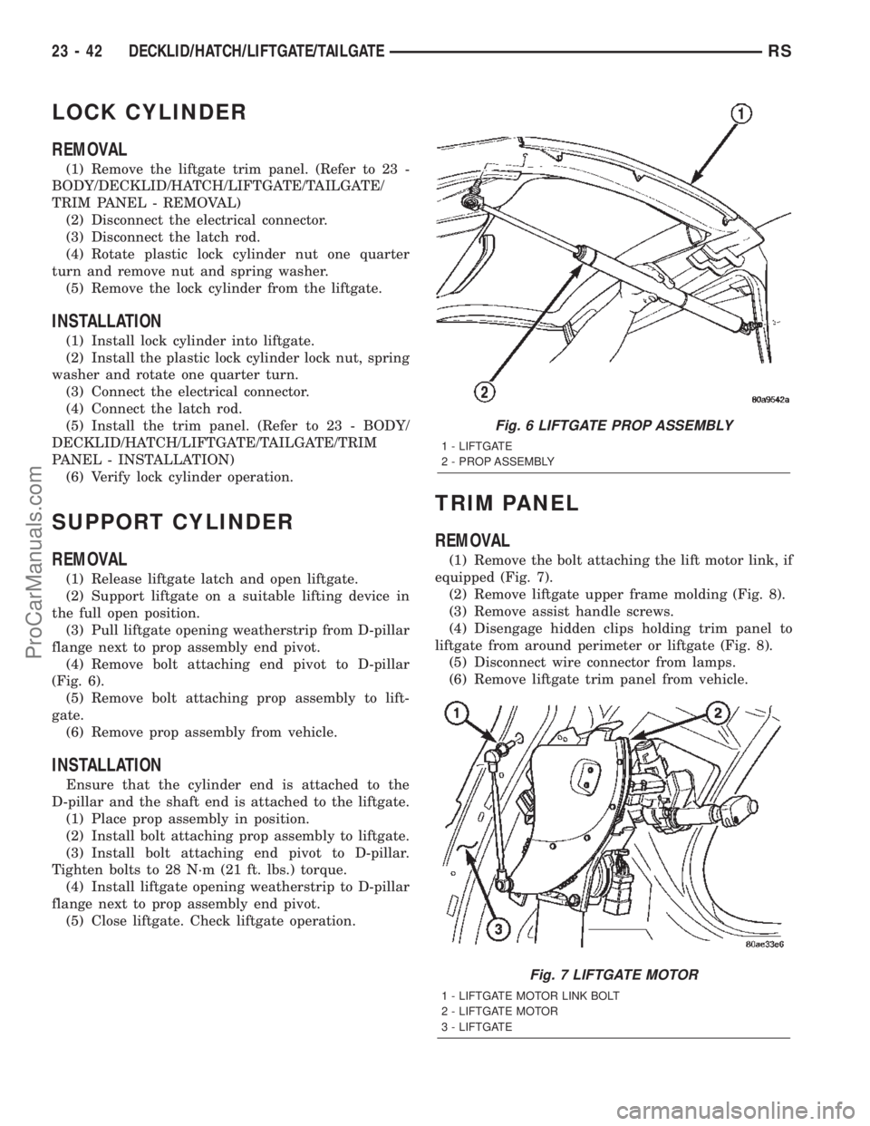
(Fig. 6).
(5) Remove bolt attaching prop assembly to lift-
gate.
(6) Remove prop assembly from vehicle.
INSTALLATION
Ensure that the cylinder end is attached to the
D-pillar and the shaft end is attached to the liftgate.
(1) Place prop assembly in position.
(2) Install bolt attaching prop assembly to liftgate.
(3) Install bolt attaching end pivot to D-pillar.
Tighten bolts to 28 N´m (21 ft. lbs.) torque.
(4) Install liftgate opening weatherstrip to D-pillar
flange next to prop assembly end pivot.
(5) Close liftgate. Check liftgate operation.
TRIM PANEL
REMOVAL
(1) Remove the bolt attaching the lift motor link, if
equipped (Fig. 7).
(2) Remove liftgate upper frame molding (Fig. 8).
(3) Remove assist handle screws.
(4) Disengage hidden clips holding trim panel to
liftgate from around perimeter or liftgate (Fig. 8).
(5) Disconnect wire connector from lamps.
(6) Remove liftgate trim panel from vehicle.
Fig. 6 LIFTGATE PROP ASSEMBLY
1 - LIFTGATE
2 - PROP ASSEMBLY
Fig. 7 LIFTGATE MOTOR
1 - LIFTGATE MOTOR LINK BOLT
2 - LIFTGATE MOTOR
3 - LIFTGATE
23 - 42 DECKLID/HATCH/LIFTGATE/TAILGATERS
ProCarManuals.com
Page 2034 of 2399
(4) Clean off all traces of adhesive or double sided
tape from the panel with a general purpose adhesive
remover.
INSTALLATION
(1) Clean panel surface with isopropy alcohol.
(2) Align badgeing to reference points.
(3) Install and press securely to full adhesive con-
tact
(4) Clean away any reference points.
EXTERIOR NAME PLATES -
ADHESIVE ATTACHED
REMOVAL
(1) Mark reference points before removing.
(2) Using a heat gun gently apply heat in a circu-
lar motion to loosen the adhesive bond.
(3) With your fingernail lift up and peel away
badgeing/tape from panel, using a heat gun as you
go.
(4) Clean off all traces of adhesive from the pan-
el(s) with a general purpose adhesive remover.
INSTALLATION
(1) Clean panel surface with isopropy alcohol.
(2) Remove paper carrier and align badgeing/tape
to reference points or adjacent panel.
(3) Install and press securely, using a plastic
spreader to eliminate all air bubbles.
(4) Remove top protective carrier.
(5) Clean away any reference points.
FRONT FENDER
REMOVAL
(1) Remove headlamp housing. (Refer to 8 - ELEC-
TRICAL/LAMPS/LIGHTING - EXTERIOR/HEAD-
LAMP UNIT - REMOVAL)
(2) Remove mud guard.
(3) Remove inner splash shield.
(4) Remove fender to fascia nuts.
(5)
Remove outboard cowl grille/fender bracket screw.
(6) Remove fender bolt to lower rocker panel.
(7) Remove fender bolt to lower cowl.
(8) Pull fascia away from fender.
(9) Remove bolts attaching fender to upper rail.
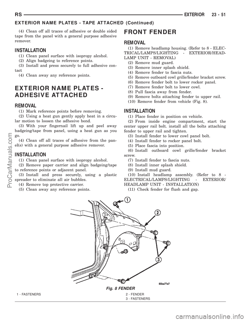
(10) Remove fender from vehicle (Fig. 8).
INSTALLATION
(1) Place fender in position on vehicle.
(2) From inside engine compartment, start the
center upper rail bolt. install all the bolts attaching
fender to upper rail and tighten.
(3) Install fender to lower cowl panel bolt.
(4) Install fender to rocker panel bolt.
(5) Place fascia into position.
(6) Install outboard cowl grille/fender bracket
screw.
(7) Install fender to fascia nuts.
(8) Install inner splash shield.
(9) Install mud guard.
(10) Install headlamp assembly. (Refer to 8 -
ELECTRICAL/LAMPS/LIGHTING - EXTERIOR/
HEADLAMP UNIT - INSTALLATION)
(11) Check fender for flush and gap.
Fig. 8 FENDER
1 - FASTENERS 2 - FENDER
3 - FASTENERS
RSEXTERIOR23-51
EXTERIOR NAME PLATES - TAPE ATTACHED (Continued)
ProCarManuals.com
Page 2041 of 2399
INSTALLATION
SHORT WHEELBASE
(1) Position the air exhauster to the hole in the
lower aperture panel (Fig. 19).
(2) Using hand pressure, press the air exhauster
into the opening in the lower aperture panel until
the snap features are fully engaged.
(3) Reinstall the rear fascia onto the body. (Refer
to 13 - FRAMES & BUMPERS/BUMPERS/REAR
FASCIA - INSTALLATION).
LONG WHEELBASE
NOTE: Models with the optional rear heater and air
conditioner do not have an air exhauster on the
right side of the vehicle, but have a plastic plug
installed in the right lower aperture panel. This plug
is installed using the same procedure used to
install the air exhauster onto the short wheelbase
model. Refer to SHORT WHEELBASE .
(1) Position the air exhauster to the hole in the
lower aperture panel (Fig. 20).
(2) Using hand pressure, press the air exhauster
into the opening in the lower aperture panel until
the snap features are fully engaged.
(3) Reinstall the quarter trim panel onto the inside
of the left or right quarter inner panel. (Refer to 23 -
BODY/INTERIOR/RIGHT QUARTER TRIM PANEL
- INSTALLATION) or (Refer to 23 - BODY/INTERI-
OR/LEFT QUARTER TRIM PANEL - INSTALLA-
TION).
ROOF JOINT MOLDING
REMOVAL
The RAP molding is set with body side molding
tape. The temperature in the work area and the vehi-
cle should be at least 21É C (70É F) to avoid damag-
ing the RAP moldings.
(1) Warm the affected stick-on molding and body
metal to approximately 38É C (100É F) using a suit-
able heat lamp or heat gun.
(2) Pull stick-on molding from painted surface.(3) Remove adhesive tape residue from painted
surface of vehicle. Use a 3M Scotch-BriteŸ Molding
Adhesive and Stripe Removal Discs, or equivalent, to
clean adhesive residue from painted surfaces. The
adhesive removal discs are available from automotive
paint suppliers. Refer to instructions supplied with
the discs for proper usage.
INSTALLATION
The RAP molding is set with body side molding
tape. The temperature in the work area and the vehi-
cle should be at least 21É C (70É F) to avoid damag-
ing the RAP moldings.
(1) If molding is to be reused;
(a) Remove tape residue from molding.
(b) Clean back of molding with MopartSuper
Kleen solvent, or equivalent.
(c) Wipe molding dry with lint free cloth.
(d) Apply new body side molding (two sided
adhesive) tape to back of molding.
(2) Clean body surface with MopartSuper Kleen
solvent, or equivalent. Wipe surface dry with lint free
cloth.
(3) Remove protective cover from tape on back of
molding.
(4) Apply molding to body from front of vehicle to
rear.
(5) Using a roller tool, roll molding onto body
panel with enough force to assure adhesion and not
bend roof panels.
SIDE VIEW MIRROR
REMOVAL
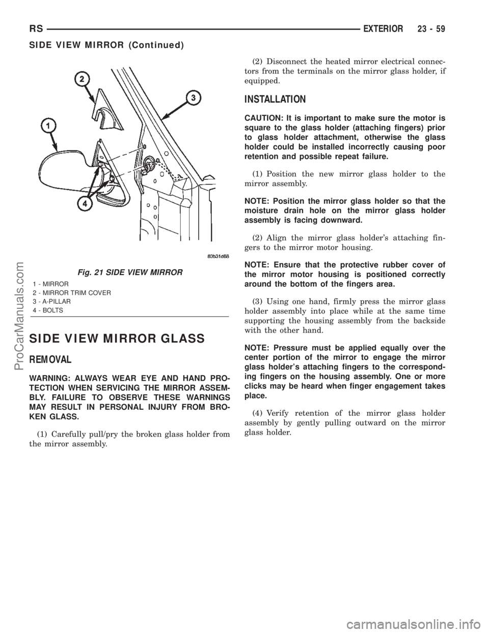
(1) Using a trim stick or equivalent, remove the
trim cover (Fig. 21).
(2) Remove the bolts.
(3) Remove the mirror from the pillar.
(4) Disconnect the electrical connector, if equipped.
INSTALLATION
(1) Connect the electrical connector, if equipped.
(2) Place side view mirror in position on vehicle
(Fig. 21).
(3) Install the bolts.
(4) Install the trim cover.
23 - 58 EXTERIORRS
REAR QUARTER PANEL/FENDER AIR EXHAUSTER (Continued)
ProCarManuals.com
Page 2042 of 2399
SIDE VIEW MIRROR GLASS
REMOVAL
WARNING: ALWAYS WEAR EYE AND HAND PRO-
TECTION WHEN SERVICING THE MIRROR ASSEM-
BLY. FAILURE TO OBSERVE THESE WARNINGS
MAY RESULT IN PERSONAL INJURY FROM BRO-
KEN GLASS.
(1) Carefully pull/pry the broken glass holder from
the mirror assembly.(2) Disconnect the heated mirror electrical connec-
tors from the terminals on the mirror glass holder, if
equipped.
INSTALLATION
CAUTION: It is important to make sure the motor is
square to the glass holder (attaching fingers) prior
to glass holder attachment, otherwise the glass
holder could be installed incorrectly causing poor
retention and possible repeat failure.
(1) Position the new mirror glass holder to the
mirror assembly.
NOTE: Position the mirror glass holder so that the
moisture drain hole on the mirror glass holder
assembly is facing downward.
(2) Align the mirror glass holder's attaching fin-
gers to the mirror motor housing.
NOTE: Ensure that the protective rubber cover of
the mirror motor housing is positioned correctly
around the bottom of the fingers area.
(3) Using one hand, firmly press the mirror glass
holder assembly into place while at the same time
supporting the housing assembly from the backside
with the other hand.
NOTE: Pressure must be applied equally over the
center portion of the mirror to engage the mirror
glass holder's attaching fingers to the correspond-
ing fingers on the housing assembly. One or more
clicks may be heard when finger engagement takes
place.
(4) Verify retention of the mirror glass holder
assembly by gently pulling outward on the mirror
glass holder.
Fig. 21 SIDE VIEW MIRROR
1 - MIRROR
2 - MIRROR TRIM COVER
3 - A-PILLAR
4 - BOLTS
RSEXTERIOR23-59
SIDE VIEW MIRROR (Continued)
ProCarManuals.com
Page 2065 of 2399
FLOOR CONSOLE TRAY
REMOVAL
(1) Remove the floor console. Refer to the Owner's
Manual for proper procedures.
(2) Remove the four screws and remove the tray.
INSTALLATION
(1) Install the floor console tray and install the
screws.
(2) Install the floor console. Refer to the Owner's
Manual for proper procedures.
FLOOR CONSOLE TRAY -
BRACKET ASSEMBLY
REMOVAL
(1) Remove the floor carpet. (Refer to 23 - BODY/
INTERIOR/CARPETS AND FLOOR MATS -
REMOVAL)
(2) Disconnect the electrical connector.
(3) Remove the four screws and remove the
bracket assembly.
INSTALLATION
(1) Install the bracket assembly and install the
four screws.
(2) Connect the electrical connector.
(3) Install the floor carpet. (Refer to 23 - BODY/
INTERIOR/CARPETS AND FLOOR MATS -
INSTALLATION)
23 - 82 INTERIORRS
ProCarManuals.com
Page 2250 of 2399
If coolant flow is verified and the heater floor out-
let temperature is insufficient, a mechanical problem
may exist.
POSSIBLE LOCATION OR CAUSE OF INSUFFICIENT HEAT
²Obstructed cowl air intake.
²Obstructed heater system outlets.
²Blend-air door not functioning properly.TEMPERATURE CONTROL
If heater floor outlet temperature cannot be
adjusted with the heater-A/C control temperature
control lever, one of the following could require ser-
vice:
²Blend-air door binding.
²Faulty blend-air door motor.
²Improper engine coolant temperature.
²Faulty heater-A/C control.
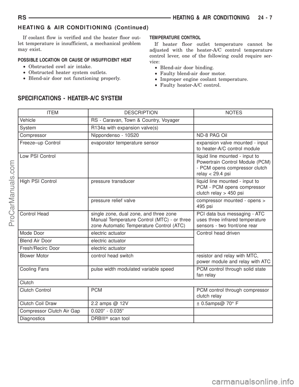
SPECIFICATIONS - HEATER-A/C SYSTEM
ITEM DESCRIPTION NOTES
Vehicle RS - Caravan, Town & Country, Voyager
System R134a with expansion valve(s)
Compressor Nippondenso - 10S20 ND-8 PAG Oil
Freeze±up Control evaporator temperature sensor expansion valve mounted - input
to heater-A/C control module
Low PSI Control liquid line mounted - input to
Powertrain Control Module (PCM)
- PCM opens compressor clutch
relay < 29.4 psi
High PSI Control pressure transducer liquid line mounted - input to
PCM - PCM opens compressor
clutch relay > 450 psi
pressure relief valve compressor mounted - opens >
495 psi
Control Head single zone, dual zone, and three zone
Manual Temperature Control (MTC) - or three
zone Automatic Temperature Control (ATC)PCI data bus messaging - ATC
uses three infrared temperature
sensors - two front/one rear
Mode Door electric actuator Control head driven
Blend Air Door electric actuator
Fresh/Recirc Door electric actuator
Blower Motor control head switch resistor and relay with MTC,
power module and relay with ATC
Cooling Fans pulse width modulated variable speed PCM control through solid state
fan relay
Clutch
Clutch Control PCM PCM control through compressor
clutch relay
Clutch Coil Draw 2.2 amps @ 12V 0.5amps@ 70É F
Compressor Clutch Air Gap 0.0209- 0.0359
Diagnostics DRBIIITscan tool
RSHEATING & AIR CONDITIONING24-7
HEATING & AIR CONDITIONING (Continued)
ProCarManuals.com