2002 CHRYSLER VOYAGER front lighting
[x] Cancel search: front lightingPage 956 of 2399

8W-51 REAR LIGHTING
Component Page
Back-Up Lamp Switch................ 8W-51-5
Battery............................ 8W-51-5
Body Control Module............ 8W-51-2, 3, 4, 5
Brake Lamp Switch................ 8W-51-2, 4
Center High Mounted Stop Lamp........ 8W-51-6
Front Control Module............. 8W-51-2, 4, 5
Fuse 2........................... 8W-51-2, 4
Fuse 3......................... 8W-51-2, 4, 5
Fuse 26.......................... 8W-51-2, 4
G101.............................. 8W-51-5
G103.............................. 8W-51-5Component Page
G302........................ 8W-51-2, 3, 4, 5
G400.............................. 8W-51-6
Integrated Power Module.......... 8W-51-2, 4, 5
Left Rear Lamp Assembly........ 8W-51-2, 3, 4, 5
Left Stop/Turn Signal Relay............ 8W-51-3
License Lamp....................... 8W-51-6
Park Lamp Relay................ 8W-51-2, 4, 5
Right Combination Relay.............. 8W-51-3
Right Rear Lamp Assembly......... 8W-51-2, 4, 5
Trailer Tow Connector................. 8W-51-3
RS8W-51 REAR LIGHTING8W-51-1
ProCarManuals.com
Page 1049 of 2399
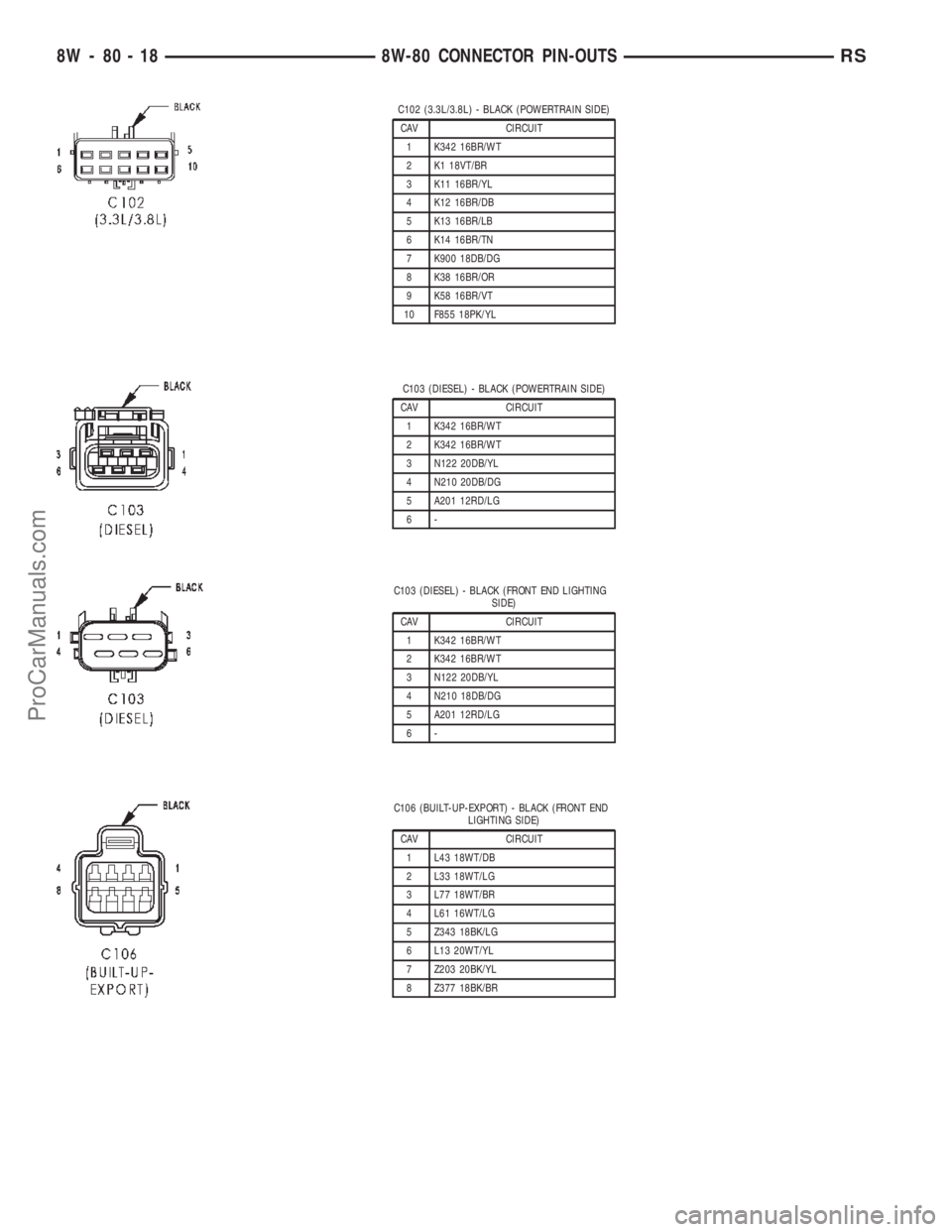
C102 (3.3L/3.8L) - BLACK (POWERTRAIN SIDE)
CAV CIRCUIT
1 K342 16BR/WT
2 K1 18VT/BR
3 K11 16BR/YL
4 K12 16BR/DB
5 K13 16BR/LB
6 K14 16BR/TN
7 K900 18DB/DG
8 K38 16BR/OR
9 K58 16BR/VT
10 F855 18PK/YL
C103 (DIESEL) - BLACK (POWERTRAIN SIDE)
CAV CIRCUIT
1 K342 16BR/WT
2 K342 16BR/WT
3 N122 20DB/YL
4 N210 20DB/DG
5 A201 12RD/LG
6-
C103 (DIESEL) - BLACK (FRONT END LIGHTING
SIDE)
CAV CIRCUIT
1 K342 16BR/WT
2 K342 16BR/WT
3 N122 20DB/YL
4 N210 18DB/DG
5 A201 12RD/LG
6-
C106 (BUILT-UP-EXPORT) - BLACK (FRONT END
LIGHTING SIDE)
CAV CIRCUIT
1 L43 18WT/DB
2 L33 18WT/LG
3 L77 18WT/BR
4 L61 16WT/LG
5 Z343 18BK/LG
6 L13 20WT/YL
7 Z203 20BK/YL
8 Z377 18BK/BR
8W - 80 - 18 8W-80 CONNECTOR PIN-OUTSRS
ProCarManuals.com
Page 1050 of 2399
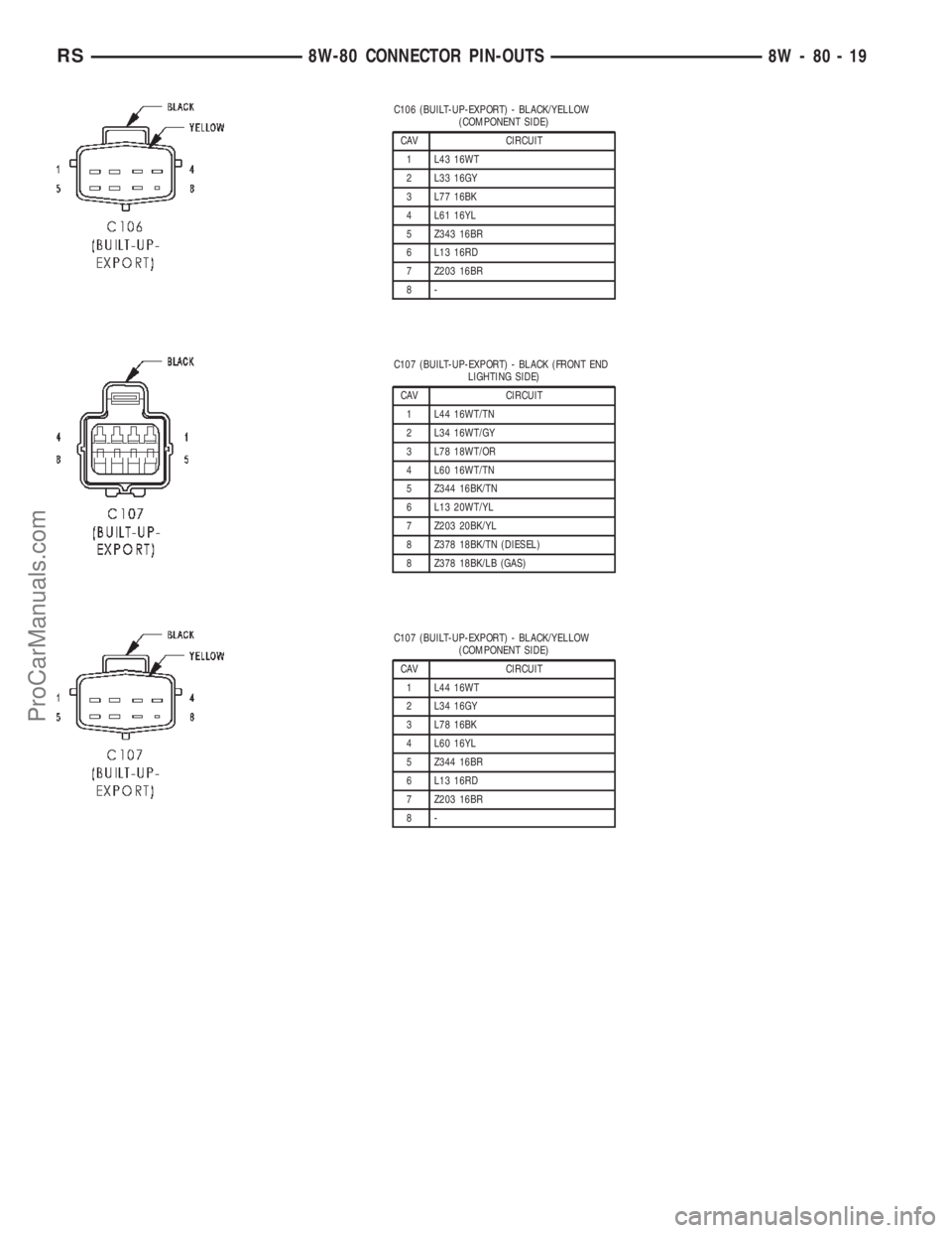
C106 (BUILT-UP-EXPORT) - BLACK/YELLOW
(COMPONENT SIDE)
CAV CIRCUIT
1 L43 16WT
2 L33 16GY
3 L77 16BK
4 L61 16YL
5 Z343 16BR
6 L13 16RD
7 Z203 16BR
8-
C107 (BUILT-UP-EXPORT) - BLACK (FRONT END
LIGHTING SIDE)
CAV CIRCUIT
1 L44 16WT/TN
2 L34 16WT/GY
3 L78 18WT/OR
4 L60 16WT/TN
5 Z344 16BK/TN
6 L13 20WT/YL
7 Z203 20BK/YL
8 Z378 18BK/TN (DIESEL)
8 Z378 18BK/LB (GAS)
C107 (BUILT-UP-EXPORT) - BLACK/YELLOW
(COMPONENT SIDE)
CAV CIRCUIT
1 L44 16WT
2 L34 16GY
3 L78 16BK
4 L60 16YL
5 Z344 16BR
6 L13 16RD
7 Z203 16BR
8-
RS8W-80 CONNECTOR PIN-OUTS8W-80-19
ProCarManuals.com
Page 1440 of 2399
FRAME & BUMPERS
TABLE OF CONTENTS
page page
BUMPERS
SPECIFICATIONS - TORQUE...............1
FRONT FASCIA
REMOVAL.............................1
INSTALLATION..........................1
FRONT BUMPER REINFORCEMENT
REMOVAL.............................2
INSTALLATION..........................2
REAR FASCIA
REMOVAL.............................3
INSTALLATION..........................3
REAR BUMPER REINFORCEMENT
REMOVAL.............................3
INSTALLATION..........................3
REAR FASCIA - SCUFF PAD
REMOVAL.............................4INSTALLATION..........................4
FRAME
SPECIFICATIONS
FRAME DIMENSIONS...................4
SPECIFICATIONS - TORQUE.............9
FRONT CRADLE CROSSMEMBER
DESCRIPTION
DESCRIPTION - FRONT CRADLE
CROSSMEMBER.......................9
DESCRIPTION - FRONT CRADLE
CROSSMEMBER THREAD REPAIR.........9
REMOVAL.............................10
INSTALLATION.........................12
FRONT CROSSMEMBER MOUNT BUSHINGS
REMOVAL.............................12
INSTALLATION.........................12
BUMPERS
SPECIFICATIONS - TORQUE
DESCRIPTION N´m Ft. Lbs. In. Lbs.
Front bumper reinforcement attaching nut 54 40 Ð
Rear bumper reinforcement attaching nut 27 20 Ð
FRONT FASCIA
REMOVAL
(1) Release hood latch and open hood.
(2) Remove the headlamp assemblies (Refer to 8 -
ELECTRICAL/LAMPS/LIGHTING - EXTERIOR/
HEADLAMP - REMOVAL).
(3) Hoist vehicle and support with safety stands.
(4) Remove the five bolts attaching bottom of fas-
cia/air dam to radiator closure panel.
(5) Remove front wheels.
(6) Remove front wheelhouse splash shields fasten-
ers as necessary to gain access to bolts attaching
front fascia to fender. (Refer to 23 - BODY/EXTERI-
OR/ WHEELHOUSE SPLASH SHIELD - REMOV-
AL).
(7) Remove the two bolts and two nuts attaching
fascia to the front fenders (Fig. 1).
(8) Disconnect fog lamp wire connectors, if neces-
sary.
(9) Lower vehicle.(10) Remove two bolts attaching the upper grille
support to the headlamp mounting panel at each side
of the grille.
(11) Remove bumper fascia from vehicle.
INSTALLATION
(1) Position front bumper fascia on vehicle.
(2) Install the two bolts attaching fascia to head-
lamp mounting panel at each side of grille.
(3) Hoist vehicle and support with safety stands.
(4) Install the two bolts and two nuts attaching
fascia to the front fenders (Fig. 1). The fascia should
be flush to fender.
(5) Install front wheelhouse splash shields fasten-
ers. (Refer to 23 - BODY/EXTERIOR/ WHEEL-
HOUSE SPLASH SHIELD - INSTALLATION).
(6) Install front wheels.
(7) Connect fog lamp wire connectors, if necessary.
(8) Install the five bolts attaching bottom of fascia
to radiator closure panel.
(9) Lower the vehicle.
RSFRAME & BUMPERS13-1
ProCarManuals.com
Page 1441 of 2399

(10) Install the headlamp assemblies. (Refer to 8 -
ELECTRICAL/LAMPS/LIGHTING - EXTERIOR/
HEADLAMP - INSTALLATION).
FRONT BUMPER
REINFORCEMENT
REMOVAL
(1) Remove front bumper fascia. (Refer to 13 -
FRAMES & BUMPERS/BUMPERS/FRONT FASCIA
- REMOVAL)
(2) Support front bumper reinforcement on a suit-
able lifting device.
(3) Remove the four nuts attaching front bumper
reinforcement to frame rail (Fig. 2).
(4) Remove front bumper reinforcement from vehi-
cle.
INSTALLATION
NOTE: Check position of the arrows molded into
the foam for correct orientation.
(1) Support front bumper reinforcement using a
suitable lifting device and lift into position.
(2) Install the four nuts attaching reinforcement to
frame rails. Tighten nuts to 54 N´m (40 ft. lbs.)
torque.
(3) Install front fascia. (Refer to 13 - FRAMES &
BUMPERS/BUMPERS/FRONT FASCIA - INSTAL-
LATION).
Fig. 1 FRONT BUMPER FASCIA
1 - FRONT BUMPER FASCIA
2 - FRONT BUMPER REINFORCEMENT
3 - RADIATOR ENCLOSURE
Fig. 2 FRT BUMPER REINFORCEMENT
1 - FRONT BUMPER REINFORCEMENT
2 - FRAME RAILS
13 - 2 FRAME & BUMPERSRS
FRONT FASCIA (Continued)
ProCarManuals.com
Page 2034 of 2399
(4) Clean off all traces of adhesive or double sided
tape from the panel with a general purpose adhesive
remover.
INSTALLATION
(1) Clean panel surface with isopropy alcohol.
(2) Align badgeing to reference points.
(3) Install and press securely to full adhesive con-
tact
(4) Clean away any reference points.
EXTERIOR NAME PLATES -
ADHESIVE ATTACHED
REMOVAL
(1) Mark reference points before removing.
(2) Using a heat gun gently apply heat in a circu-
lar motion to loosen the adhesive bond.
(3) With your fingernail lift up and peel away
badgeing/tape from panel, using a heat gun as you
go.
(4) Clean off all traces of adhesive from the pan-
el(s) with a general purpose adhesive remover.
INSTALLATION
(1) Clean panel surface with isopropy alcohol.
(2) Remove paper carrier and align badgeing/tape
to reference points or adjacent panel.
(3) Install and press securely, using a plastic
spreader to eliminate all air bubbles.
(4) Remove top protective carrier.
(5) Clean away any reference points.
FRONT FENDER
REMOVAL
(1) Remove headlamp housing. (Refer to 8 - ELEC-
TRICAL/LAMPS/LIGHTING - EXTERIOR/HEAD-
LAMP UNIT - REMOVAL)
(2) Remove mud guard.
(3) Remove inner splash shield.
(4) Remove fender to fascia nuts.
(5)
Remove outboard cowl grille/fender bracket screw.
(6) Remove fender bolt to lower rocker panel.
(7) Remove fender bolt to lower cowl.
(8) Pull fascia away from fender.
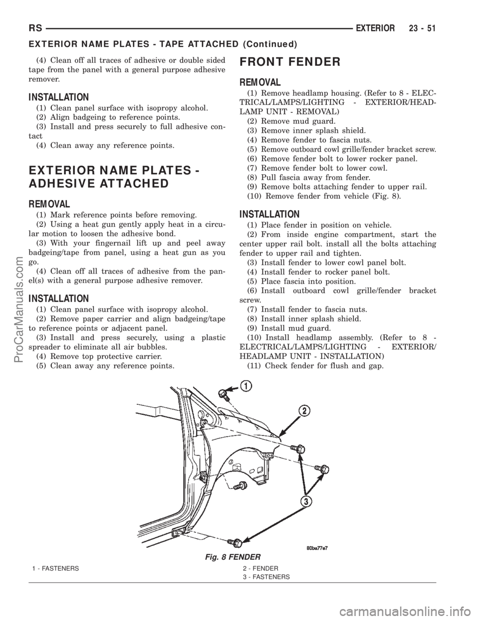
(9) Remove bolts attaching fender to upper rail.
(10) Remove fender from vehicle (Fig. 8).
INSTALLATION
(1) Place fender in position on vehicle.
(2) From inside engine compartment, start the
center upper rail bolt. install all the bolts attaching
fender to upper rail and tighten.
(3) Install fender to lower cowl panel bolt.
(4) Install fender to rocker panel bolt.
(5) Place fascia into position.
(6) Install outboard cowl grille/fender bracket
screw.
(7) Install fender to fascia nuts.
(8) Install inner splash shield.
(9) Install mud guard.
(10) Install headlamp assembly. (Refer to 8 -
ELECTRICAL/LAMPS/LIGHTING - EXTERIOR/
HEADLAMP UNIT - INSTALLATION)
(11) Check fender for flush and gap.
Fig. 8 FENDER
1 - FASTENERS 2 - FENDER
3 - FASTENERS
RSEXTERIOR23-51
EXTERIOR NAME PLATES - TAPE ATTACHED (Continued)
ProCarManuals.com
Page 2318 of 2399
ward far enough to disengage the engine compart-
ment ends of the tubes from the dash panel seal.
(14) Remove the heater core tubes and sealing
plate as a unit from beneath the instrument panel.
(15) Use absorbent toweling to clean up any
engine coolant spills from the preceding operation.
REMOVAL - HEATER CORE
WARNING: REFER TO THE APPLICABLE WARN-
INGS AND CAUTIONS FOR THIS SYSTEM BEFORE
PERFORMING THE FOLLOWING OPERATION.
(Refer to 24 - HEATING & AIR CONDITIONING/
PLUMBING FRONT - WARNING - HEATER PLUMB-
ING).
WARNING: ON VEHICLES EQUIPPED WITH AIR-
BAGS, DISABLE THE AIRBAG SYSTEM BEFORE
ATTEMPTING ANY STEERING WHEEL, STEERING
COLUMN, OR INSTRUMENT PANEL COMPONENT
DIAGNOSIS OR SERVICE. DISCONNECT AND ISO-
LATE THE BATTERY NEGATIVE (GROUND) CABLE,
THEN WAIT TWO MINUTES FOR THE AIRBAG SYS-
TEM CAPACITOR TO DISCHARGE BEFORE PER-
FORMING FURTHER DIAGNOSIS OR SERVICE. THIS
IS THE ONLY SURE WAY TO DISABLE THE AIRBAG
SYSTEM. FAILURE TO TAKE THE PROPER PRE-
CAUTIONS COULD RESULT IN ACCIDENTAL AIR-
BAG DEPLOYMENT AND POSSIBLE PERSONAL
INJURY.
(1) Drain the engine cooling system. (Refer to 7 -
COOLING - STANDARD PROCEDURE - COOLING
SYSTEM DRAIN).
(2) Disconnect and isolate the battery negative
cable.
(3) Remove the silencer boot fasteners located
around the base of the lower steering shaft from the
dash panel so that it may be pushed aside.
(4) Remove the brake lamp switch from its mount-
ing bracket. (Refer to 8 - ELECTRICAL/LAMPS/
LIGHTING - EXTERIOR/BRAKE LAMP SWITCH -
REMOVAL).
(5) Disconnect the power brake booster input rod
(push rod) from the pin on the brake pedal arm.
(Refer to 5 - BRAKES - ABS/HYDRAULIC/ME-
CHANICAL/POWER BRAKE BOOSTER - REMOV-
AL).
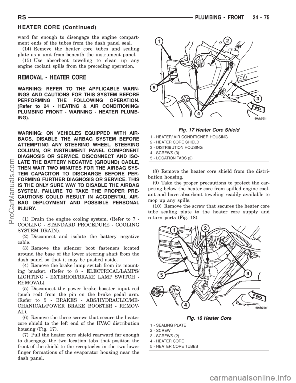
(6) Remove the three screws that secure the heater
core shield to the left end of the HVAC distribution
housing (Fig. 17).
(7) Pull the heater core shield rearward far enough
to disengage the two location tabs that position the
front of the shield to the receptacles in the two lower
finger formations of the evaporator housing near the
dash panel.(8) Remove the heater core shield from the distri-
bution housing.
(9) Take the proper precautions to protect the car-
peting below the heater core from spilled engine cool-
ant and have absorbent toweling readily available to
mop up any spills.
(10) Remove the screw that secures the heater core
tube sealing plate to the heater core supply and
return ports (Fig. 18).
Fig. 17 Heater Core Shield
1 - HEATER/ AIR CONDITIONER HOUSING
2 - HEATER CORE SHIELD
3 - DISTRIBUTION HOUSING
4 - SCREWS (3)
5 - LOCATION TABS (2)
Fig. 18 Heater Core
1 - SEALING PLATE
2 - SCREW
3 - SCREWS (2)
4 - HEATER CORE
5 - HEATER CORE TUBES
RSPLUMBING - FRONT24-75
HEATER CORE (Continued)
ProCarManuals.com
Page 2320 of 2399
(6) Install and tighten the screw that secures the
heater core tube sealing plate to the heater core sup-
ply and return ports. Tighten the screw to 3 N´m (27
in. lbs.).
(7) Position the heater core shield onto the distri-
bution housing. Be certain that the two location tabs
on the front of the shield are engaged in the recepta-
cles in the two lower finger formations of the evapo-
rator housing near the dash panel.
(8) Install and tighten the three screws that secure
the heater core shield to the left end of the HVAC
distribution housing. Tighten the screws to 2 N´m (17
in. lbs.).
(9) Reinstall the silencer under the driver side end
of the instrument panel. (Refer to 23 - BODY/IN-
STRUMENT PANEL/INSTRUMENT PANEL
SILENCER - INSTALLATION).
(10) Reconnect the heater hoses to the heater hose
tubes. (Refer to 24 - HEATING & AIR CONDITION-
ING/PLUMBING - FRONT/HEATER HOSE -
INSTALLATION).
(11) Reconnect the battery negative cable.
(12) Refill the engine cooling system. (Refer to 7 -
COOLING - STANDARD PROCEDURE - COOLING
SYSTEM REFILL).
INSTALLATION - HEATER CORE
WARNING: REFER TO THE APPLICABLE WARN-
INGS AND CAUTIONS FOR THIS SYSTEM BEFORE
PERFORMING THE FOLLOWING OPERATION.
(Refer to 24 - HEATING & AIR CONDITIONING/
PLUMBING FRONT - WARNING - HEATER PLUMB-
ING).
WARNING: ON VEHICLES EQUIPPED WITH AIR-
BAGS, DISABLE THE AIRBAG SYSTEM BEFORE
ATTEMPTING ANY STEERING WHEEL, STEERING
COLUMN, OR INSTRUMENT PANEL COMPONENT
DIAGNOSIS OR SERVICE. DISCONNECT AND ISO-
LATE THE BATTERY NEGATIVE (GROUND) CABLE,
THEN WAIT TWO MINUTES FOR THE AIRBAG SYS-
TEM CAPACITOR TO DISCHARGE BEFORE PER-
FORMING FURTHER DIAGNOSIS OR SERVICE. THIS
IS THE ONLY SURE WAY TO DISABLE THE AIRBAG
SYSTEM. FAILURE TO TAKE THE PROPER PRE-
CAUTIONS COULD RESULT IN ACCIDENTAL AIR-
BAG DEPLOYMENT AND POSSIBLE PERSONAL
INJURY.(1) While pushing the brake pedal downward and
pulling the accelerator pedal upward far enough for
clearance, slide the heater core into the distribution
housing.
(2) Install and tighten the two screws that secure
the heater core mounting plate to the distribution
housing. Tighten the screws to 2 N´m (17 in. lbs.).
(3) Remove the plugs or tape from the heater core
tube fittings and both heater core ports.
(4) Position both heater core tubes and the sealing
plate simultaneously to the heater core supply and
return ports.
(5) The heater core tubes each have a slot that
must be indexed to a location tab within each of the
heater core ports. Adjust the position of the tubes as
required so that the sealing plate fits flush against
the heater core supply and return ports, which indi-
cates that the tubes are properly indexed.
(6) Install and tighten the screw that secures the
heater core tube sealing plate to the heater core sup-
ply and return ports. Tighten the screw to 3 N´m (27
in. lbs.).
(7) Position the heater core shield onto the distri-
bution housing. Be certain that the two location tabs
on the front of the shield are engaged in the recepta-
cles in the two lower finger formations of the evapo-
rator housing near the dash panel.
(8) Install and tighten the three screws that secure
the heater core shield to the left end of the HVAC
distribution housing. Tighten the screws to 2 N´m (17
in. lbs.).
(9) Reconnect the power brake booster input rod
(push rod) to the pin on the brake pedal arm(Refer to
5 - BRAKES/HYDRAULIC/MECHANICAL/POWER
BRAKE BOOSTER - INSTALLATION).
(10) Reinstall the brake lamp switch into its
mounting bracket(Refer to 8 - ELECTRICAL/LAMPS/
LIGHTING - EXTERIOR/BRAKE LAMP SWITCH -
INSTALLATION).
(11) Reinstall the silencer boot around the base of
the lower steering shaft on the dash panel.
(12) Reconnect the battery negative cable.
(13) Refill the engine cooling system. (Refer to 7 -
COOLING - STANDARD PROCEDURE - COOLING
SYSTEM REFILL).
(14) Operate system for two thermostat cycles to
assure elimination of air in the system.
RSPLUMBING - FRONT24-77
HEATER CORE (Continued)
ProCarManuals.com