Page 1833 of 2399
OPERATION
The Brake/Transmission Shift Interlock (BTSI)
Solenoid prevents the transmission shift lever from
being moved out of PARK (P) unless the brake pedal
is applied. The BTSI solenoid is hardwired to and
controlled by the Intelligent Power Module (IPM).
Battery voltage is applied to one side of the solenoid
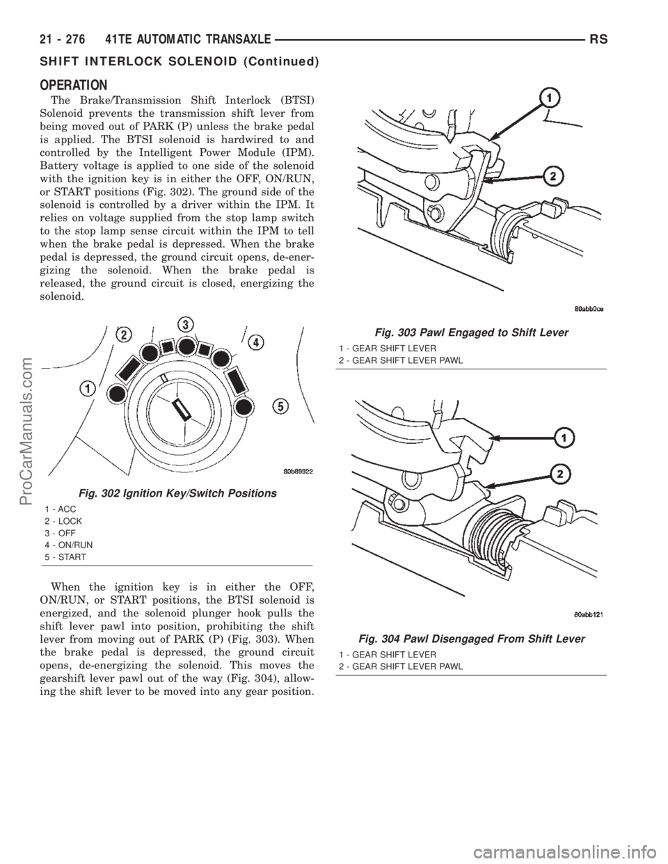
with the ignition key is in either the OFF, ON/RUN,
or START positions (Fig. 302). The ground side of the
solenoid is controlled by a driver within the IPM. It
relies on voltage supplied from the stop lamp switch
to the stop lamp sense circuit within the IPM to tell
when the brake pedal is depressed. When the brake
pedal is depressed, the ground circuit opens, de-ener-
gizing the solenoid. When the brake pedal is
released, the ground circuit is closed, energizing the
solenoid.
When the ignition key is in either the OFF,
ON/RUN, or START positions, the BTSI solenoid is
energized, and the solenoid plunger hook pulls the
shift lever pawl into position, prohibiting the shift
lever from moving out of PARK (P) (Fig. 303). When
the brake pedal is depressed, the ground circuit
opens, de-energizing the solenoid. This moves the
gearshift lever pawl out of the way (Fig. 304), allow-
ing the shift lever to be moved into any gear position.
Fig. 302 Ignition Key/Switch Positions
1 - ACC
2 - LOCK
3 - OFF
4 - ON/RUN
5-START
Fig. 303 Pawl Engaged to Shift Lever
1 - GEAR SHIFT LEVER
2 - GEAR SHIFT LEVER PAWL
Fig. 304 Pawl Disengaged From Shift Lever
1 - GEAR SHIFT LEVER
2 - GEAR SHIFT LEVER PAWL
21 - 276 41TE AUTOMATIC TRANSAXLERS
SHIFT INTERLOCK SOLENOID (Continued)
ProCarManuals.com
Page 1834 of 2399
A conventional mechanical interlock system is also
used. This system manually prohibits shifter move-
ment when the ignition switch is in the LOCK or
ACC positions. Solenoid operation is not required in
these key positions.
For intended BTSI system operation, refer to the
following chart:
ACTION EXPECTED RESPONSE
1. Turn key to the9OFF9
position.1. Shifter CAN be shifted
out of park with brake
pedal applied.
2. Turn key to the
9ON/RUN9position.2. Shifter CANNOT be
shifted out of park.
3. Turn key to the
9ON/RUN9position and
depress the brake pedal.3. Shifter CAN be shifted
out of park.
4. Leave shifter in any
gear and try to return key
to the9LOCK9or9ACC9
position.4. Key cannot be
returned to the9LOCK9or
9ACC9position.
5. Return shifter to
9PARK9and try to remove
the key.5. Key can be removed
(after returning to9LOCK9
position).
6. With the key removed,
try to shift out of9PARK9.6. Shifter cannot be
shifted out of9PARK9.
NOTE: Any failure to meet these expected
responses requires system adjustment or repair.
DIAGNOSIS AND TESTING - BRAKE/
TRANSMISSION SHIFT INTERLOCK SOLENOID
For intended BTSI system operation, refer to the
following chart:
ACTION EXPECTED RESPONSE
1. Turn key to the9OFF9
position.1. Shifter CAN be shifted
out of park with brake
pedal applied.
2. Turn key to the
9ON/RUN9position.2. Shifter CANNOT be
shifted out of park.
3. Turn key to the
9ON/RUN9position and
depress the brake pedal.3. Shifter CAN be shifted
out of park.
4. Leave shifter in any
gear and try to return key
to the9LOCK9or9ACC9
position.4. Key cannot be
returned to the9LOCK9or
9ACC9position.
5. Return shifter to
9PARK9and try to remove
the key.5. Key can be removed
(after returning to9LOCK9
position).
ACTION EXPECTED RESPONSE
6. With the key removed,
try to shift out of9PARK9.6. Shifter cannot be
shifted out of9PARK9.
NOTE: Any failure to meet these expected
responses requires system repair. Refer to the
appropriate Diagnostic Information.
REMOVAL
(1) Disconnect battery negative cable.
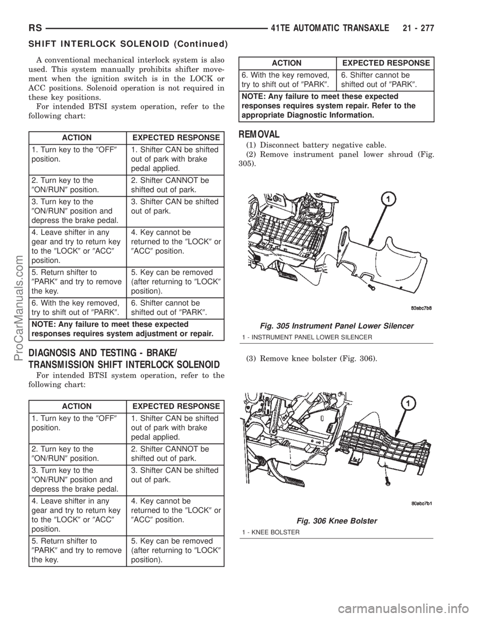
(2) Remove instrument panel lower shroud (Fig.
305).
(3) Remove knee bolster (Fig. 306).
Fig. 305 Instrument Panel Lower Silencer
1 - INSTRUMENT PANEL LOWER SILENCER
Fig. 306 Knee Bolster
1 - KNEE BOLSTER
RS41TE AUTOMATIC TRANSAXLE21 - 277
SHIFT INTERLOCK SOLENOID (Continued)
ProCarManuals.com
Page 1835 of 2399
(4) Remove steering column lower shroud.
(5) Disconnect brake/transmission shift interlock
(BTSI) solenoid connector (Fig. 307).
(6)
Remove two (2) solenoid-to-column screws (Fig.
308).
(7) Remove solenoid.
INSTALLATION
(1) Place interlock solenoid into position ensuring
hook on end of solenoid plunger engages gearshift
lever pawl pin. Install and tighten screws (Fig. 309).
(2) Verify gearshift lever is in PARK (P) and con-
nect solenoid connector (Fig. 310).
Fig. 307 BTSI Solenoid Connector
1 - BTSI SOLENOID
2 - SOLENOID CONNECTOR
Fig. 308 Solenoid Retaining Screw
1 - SOLENOID RETAINING SCREW (2)
Fig. 309 Solenoid Retaining Screw
1 - SOLENOID RETAINING SCREW (2)
Fig. 310 BTSI Solenoid Connector
1 - BTSI SOLENOID
2 - SOLENOID CONNECTOR
21 - 278 41TE AUTOMATIC TRANSAXLERS
SHIFT INTERLOCK SOLENOID (Continued)
ProCarManuals.com
Page 1917 of 2399
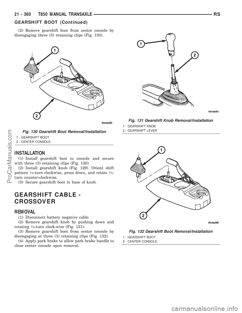
(2) Remove gearshift boot from center console by
disengaging three (3) retaining clips (Fig. 130).
INSTALLATION
(1) Install gearshift boot to console and secure
with three (3) retaining clips (Fig. 130).
(2) Install gearshift knob (Fig. 129). Orient shift
pattern
1¤4-turn clockwise, press down, and rotate1¤4-
turn counter-clockwise.
(3) Secure gearshift boot to base of knob.
GEARSHIFT CABLE -
CROSSOVER
REMOVAL
(1) Disconnect battery negative cable.
(2) Remove gearshift knob by pushing down and
rotating
1¤4-turn clock-wise (Fig. 131).
(3) Remove gearshift boot from center console by
disengaging at three (3) retaining clips (Fig. 132).
(4) Apply park brake to allow park brake handle to
clear center console upon removal.
Fig. 130 Gearshift Boot Removal/Installation
1 - GEARSHIFT BOOT
2 - CENTER CONSOLE
Fig. 131 Gearshift Knob Removal/Installation
1 - GEARSHIFT KNOB
2 - GEARSHIFT LEVER
Fig. 132 Gearshift Boot Removal/Installation
1 - GEARSHIFT BOOT
2 - CENTER CONSOLE
21 - 360 T850 MANUAL TRANSAXLERS
GEARSHIFT BOOT (Continued)
ProCarManuals.com
Page 1924 of 2399
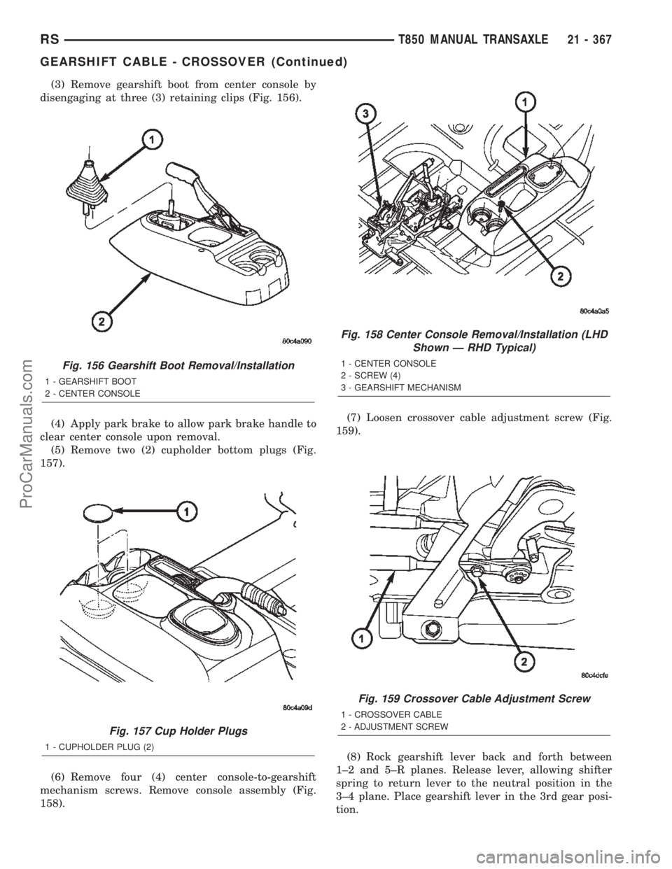
(3) Remove gearshift boot from center console by
disengaging at three (3) retaining clips (Fig. 156).
(4) Apply park brake to allow park brake handle to
clear center console upon removal.
(5) Remove two (2) cupholder bottom plugs (Fig.
157).
(6) Remove four (4) center console-to-gearshift
mechanism screws. Remove console assembly (Fig.
158).(7) Loosen crossover cable adjustment screw (Fig.
159).
(8) Rock gearshift lever back and forth between
1±2 and 5±R planes. Release lever, allowing shifter
spring to return lever to the neutral position in the
3±4 plane. Place gearshift lever in the 3rd gear posi-
tion.
Fig. 156 Gearshift Boot Removal/Installation
1 - GEARSHIFT BOOT
2 - CENTER CONSOLE
Fig. 157 Cup Holder Plugs
1 - CUPHOLDER PLUG (2)
Fig. 158 Center Console Removal/Installation (LHD
Shown Ð RHD Typical)
1 - CENTER CONSOLE
2 - SCREW (4)
3 - GEARSHIFT MECHANISM
Fig. 159 Crossover Cable Adjustment Screw
1 - CROSSOVER CABLE
2 - ADJUSTMENT SCREW
RST850 MANUAL TRANSAXLE21 - 367
GEARSHIFT CABLE - CROSSOVER (Continued)
ProCarManuals.com
Page 1925 of 2399
(9) Torque crossover lever adjustment screw to 8
N´m (70 in. lbs.).No load should be applied to
the shifter lever in any direction (hands off)
while tightening screw.
(10) Verify gearshift lever travel through all gear
ranges with engine off (not running).
(11) Install center console assembly (Fig. 158).
Install and torque center console-to-gearshift mecha-
nism screws to 5 N´m (45 in. lbs.).
(12) Install cupholder plugs (Fig. 157).
(13) Install gearshift boot to console (Fig. 156).
Secure boot to console with three (3) retainer clips.
(14) Install gearshift knob to gearshift lever (Fig.
155). Orient shift pattern on knob
1¤4-turn clockwise,
push down and rotate1¤4-turn counter-clockwise and
release. Secure boot to knob.
(15) Connect battery negative cable.
GEARSHIFT CABLE -
SELECTOR
REMOVAL
(1) Disconnect battery negative cable.
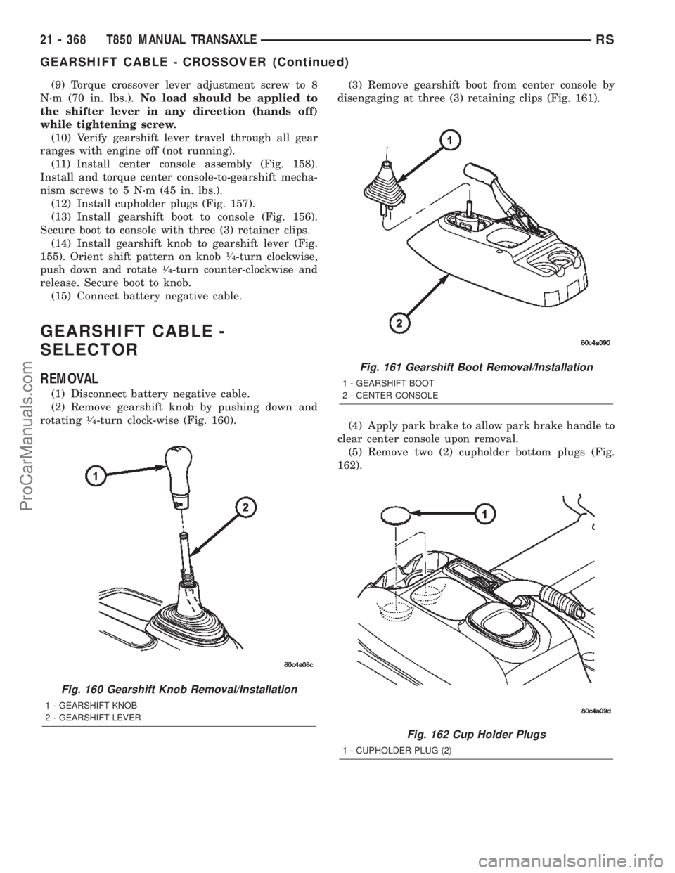
(2) Remove gearshift knob by pushing down and
rotating
1¤4-turn clock-wise (Fig. 160).(3) Remove gearshift boot from center console by
disengaging at three (3) retaining clips (Fig. 161).
(4) Apply park brake to allow park brake handle to
clear center console upon removal.
(5) Remove two (2) cupholder bottom plugs (Fig.
162).
Fig. 160 Gearshift Knob Removal/Installation
1 - GEARSHIFT KNOB
2 - GEARSHIFT LEVER
Fig. 161 Gearshift Boot Removal/Installation
1 - GEARSHIFT BOOT
2 - CENTER CONSOLE
Fig. 162 Cup Holder Plugs
1 - CUPHOLDER PLUG (2)
21 - 368 T850 MANUAL TRANSAXLERS
GEARSHIFT CABLE - CROSSOVER (Continued)
ProCarManuals.com
Page 1932 of 2399
GEARSHIFT MECHANISM
REMOVAL
(1) Disconnect battery negative cable.
(2) Remove gearshift knob by pushing down and
rotating
1¤4turn clock-wise (Fig. 185).
(3) Remove gearshift boot from center console by
disengaging at three (3) retaining clips (Fig. 186).(4) Apply park brake to allow park brake handle to
clear center console upon removal.
(5) Remove two (2) cupholder bottom plugs (Fig.
187).
(6) Remove four (4) center console-to-gearshift
mechanism screws. Remove console assembly (Fig.
188).
Fig. 185 Gearshift Knob Removal/Installation
1 - GEARSHIFT KNOB
2 - GEARSHIFT LEVER
Fig. 186 Gearshift Boot Removal/Installation
1 - GEARSHIFT BOOT
2 - CENTER CONSOLE
Fig. 187 Cup Holder Plugs
1 - CUPHOLDER PLUG (2)
Fig. 188 Center Console Removal/Installation (LHD
Shown Ð RHD Typical)
1 - CENTER CONSOLE
2 - SCREW (4)
3 - GEARSHIFT MECHANISM
RST850 MANUAL TRANSAXLE21 - 375
ProCarManuals.com
Page 1934 of 2399
(11) Remove selector cable from gearshift mecha-
nism (Fig. 193).
(12) Remove four (4) gearshift mechanism-to-park
brake bracket nuts. Remove gearshift mechanism
from bracket (Fig. 194).INSTALLATION
(1) Install gearshift mechanism to park brake
bracket (Fig. 195). Install and torque nuts to 12 N´m
(108 in. lbs.).
(2) Install selector cable to gearshift mechanism
(Fig. 196). Install retainer clip (Fig. 197).
Fig. 193 Selector Cable at Gearshift Mechanism
1 - GEARSHIFT MECHANISM
2 - SELECTOR CABLE
Fig. 194 Gearshift Mechanism Removal/Installation
(RHD Shown Ð LHD Typical)
1 - GEARSHIFT MECHANISM
2 - PARK BRAKE BRACKET
3 - NUT (4)
Fig. 195 Gearshift Mechanism Removal/Installation
(RHD Shown Ð LHD Typical)
1 - GEARSHIFT MECHANISM
2 - PARK BRAKE BRACKET
3 - NUT (4)
Fig. 196 Selector Cable at Gearshift Mechanism
1 - GEARSHIFT MECHANISM
2 - SELECTOR CABLE
RST850 MANUAL TRANSAXLE21 - 377
GEARSHIFT MECHANISM (Continued)
ProCarManuals.com