2002 CHRYSLER VOYAGER Brake
[x] Cancel search: BrakePage 1674 of 2399
DIAGNOSIS AND TESTING - BRAKE/
TRANSMISSION SHIFT INTERLOCK SOLENOID
For intended BTSI system operation, refer to the
following chart:
ACTION EXPECTED RESPONSE
1. Turn key to the9OFF9
position.1. Shifter CAN be shifted
out of park with brake
pedal applied.
2. Turn key to the
9ON/RUN9position.2. Shifter CANNOT be
shifted out of park.
3. Turn key to the
9ON/RUN9position and
depress the brake pedal.3. Shifter CAN be shifted
out of park.
4. Leave shifter in any
gear and try to return key
to the9LOCK9or9ACC9
position.4. Key cannot be
returned to the9LOCK9or
9ACC9position.
5. Return shifter to
9PARK9and try to remove
the key.5. Key can be removed
(after returning to9LOCK9
position).
6. With the key removed,
try to shift out of9PARK9.6. Shifter cannot be
shifted out of9PARK9.
NOTE: Any failure to meet these expected
responses requires system repair. Refer to the
appropriate Diagnostic Information.
REMOVAL
(1) Disconnect battery negative cable.
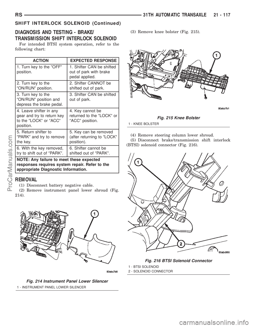
(2) Remove instrument panel lower shroud (Fig.
214).(3) Remove knee bolster (Fig. 215).
(4) Remove steering column lower shroud.
(5) Disconnect brake/transmission shift interlock
(BTSI) solenoid connector (Fig. 216).
Fig. 214 Instrument Panel Lower Silencer
1 - INSTRUMENT PANEL LOWER SILENCER
Fig. 215 Knee Bolster
1 - KNEE BOLSTER
Fig. 216 BTSI Solenoid Connector
1 - BTSI SOLENOID
2 - SOLENOID CONNECTOR
RS31TH AUTOMATIC TRANSAXLE21 - 117
SHIFT INTERLOCK SOLENOID (Continued)
ProCarManuals.com
Page 1718 of 2399
41TE AUTOMATIC TRANSAXLE
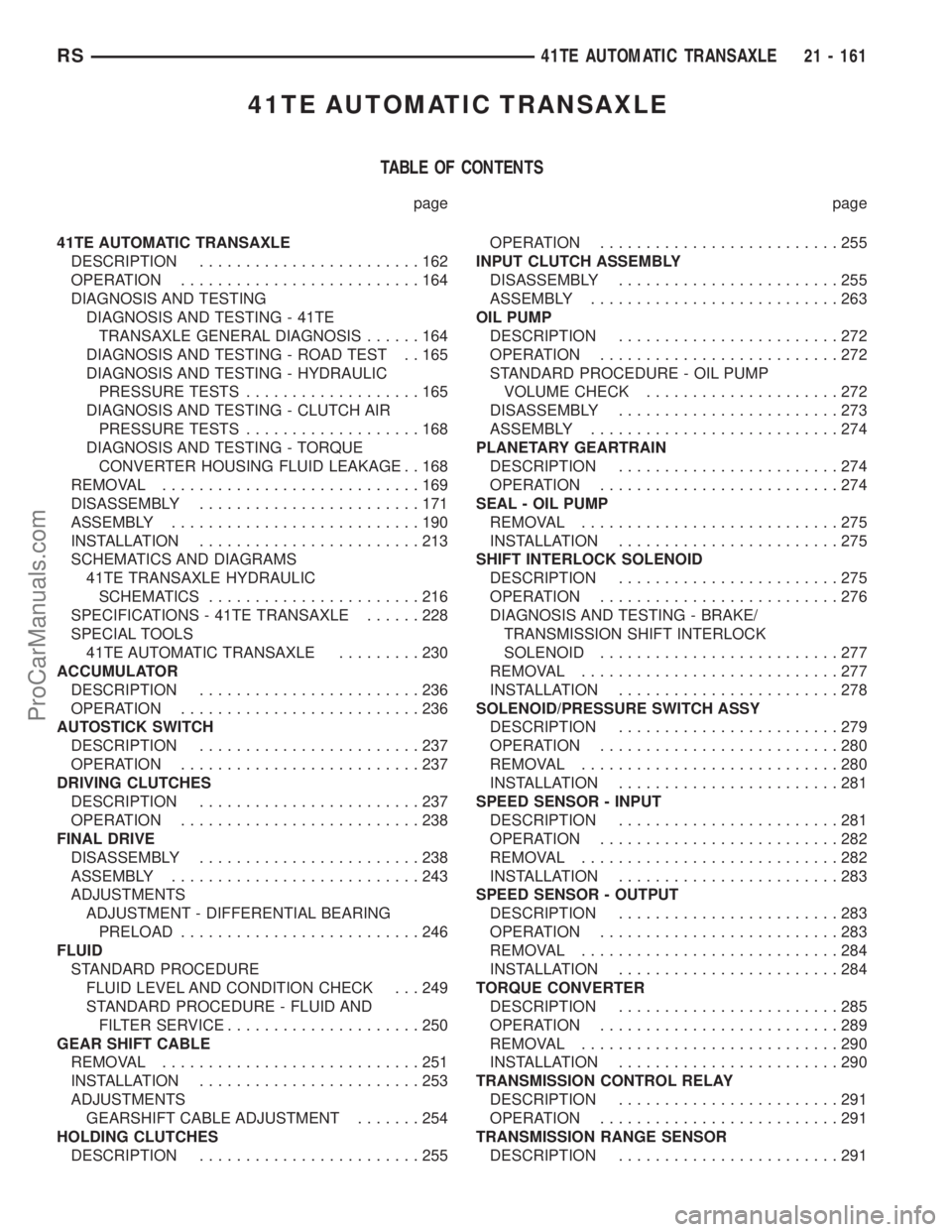
TABLE OF CONTENTS
page page
41TE AUTOMATIC TRANSAXLE
DESCRIPTION........................162
OPERATION..........................164
DIAGNOSIS AND TESTING
DIAGNOSIS AND TESTING - 41TE
TRANSAXLE GENERAL DIAGNOSIS......164
DIAGNOSIS AND TESTING - ROAD TEST . . 165
DIAGNOSIS AND TESTING - HYDRAULIC
PRESSURE TESTS...................165
DIAGNOSIS AND TESTING - CLUTCH AIR
PRESSURE TESTS...................168
DIAGNOSIS AND TESTING - TORQUE
CONVERTER HOUSING FLUID LEAKAGE . . 168
REMOVAL............................169
DISASSEMBLY........................171
ASSEMBLY...........................190
INSTALLATION........................213
SCHEMATICS AND DIAGRAMS
41TE TRANSAXLE HYDRAULIC
SCHEMATICS.......................216
SPECIFICATIONS - 41TE TRANSAXLE......228
SPECIAL TOOLS
41TE AUTOMATIC TRANSAXLE.........230
ACCUMULATOR
DESCRIPTION........................236
OPERATION..........................236
AUTOSTICK SWITCH
DESCRIPTION........................237
OPERATION..........................237
DRIVING CLUTCHES
DESCRIPTION........................237
OPERATION..........................238
FINAL DRIVE
DISASSEMBLY........................238
ASSEMBLY...........................243
ADJUSTMENTS
ADJUSTMENT - DIFFERENTIAL BEARING
PRELOAD..........................246
FLUID
STANDARD PROCEDURE
FLUID LEVEL AND CONDITION CHECK . . . 249
STANDARD PROCEDURE - FLUID AND
FILTER SERVICE.....................250
GEAR SHIFT CABLE
REMOVAL............................251
INSTALLATION........................253
ADJUSTMENTS
GEARSHIFT CABLE ADJUSTMENT.......254
HOLDING CLUTCHES
DESCRIPTION........................255OPERATION..........................255
INPUT CLUTCH ASSEMBLY
DISASSEMBLY........................255
ASSEMBLY...........................263
OIL PUMP
DESCRIPTION........................272
OPERATION..........................272
STANDARD PROCEDURE - OIL PUMP
VOLUME CHECK.....................272
DISASSEMBLY........................273
ASSEMBLY...........................274
PLANETARY GEARTRAIN
DESCRIPTION........................274
OPERATION..........................274
SEAL - OIL PUMP
REMOVAL............................275
INSTALLATION........................275
SHIFT INTERLOCK SOLENOID
DESCRIPTION........................275
OPERATION..........................276
DIAGNOSIS AND TESTING - BRAKE/
TRANSMISSION SHIFT INTERLOCK
SOLENOID..........................277
REMOVAL............................277
INSTALLATION........................278
SOLENOID/PRESSURE SWITCH ASSY
DESCRIPTION........................279
OPERATION..........................280
REMOVAL............................280
INSTALLATION........................281
SPEED SENSOR - INPUT
DESCRIPTION........................281
OPERATION..........................282
REMOVAL............................282
INSTALLATION........................283
SPEED SENSOR - OUTPUT
DESCRIPTION........................283
OPERATION..........................283
REMOVAL............................284
INSTALLATION........................284
TORQUE CONVERTER
DESCRIPTION........................285
OPERATION..........................289
REMOVAL............................290
INSTALLATION........................290
TRANSMISSION CONTROL RELAY
DESCRIPTION........................291
OPERATION..........................291
TRANSMISSION RANGE SENSOR
DESCRIPTION........................291
RS41TE AUTOMATIC TRANSAXLE21 - 161
ProCarManuals.com
Page 1724 of 2399
TEST SIX-SELECTOR IN REVERSE
(1) Attach gauges to the reverse and LR clutch
tap.
(2) Move selector lever to the (R) position.
(3) Read reverse clutch pressure with output sta-
tionary (foot on brake) and throttle opened to achieve
1500 rpm.
(4) Reverse and LR clutch pressure should read
165 to 235 psi.
(5) This test checks the reverse clutch hydraulic
circuit.
TEST RESULT INDICATIONS
(1) If proper line pressure is found in any one test,
the pump and pressure regulator are working prop-
erly.(2) Low pressure in all positions indicates a defec-
tive pump, a clogged filter, or a stuck pressure regu-
lator valve.
(3) Clutch circuit leaks are indicated if pressures
do not fall within the specified pressure range.
(4) If the overdrive clutch pressure is greater than
5 psi in Step 4 of Test Three, a worn reaction shaft
seal ring or a defective solenoid assembly is indi-
cated.
(5) If the underdrive clutch pressure is greater
than 5 psi in Step 4 of Test Two A, a defective sole-
noid assembly or TCM is the cause.
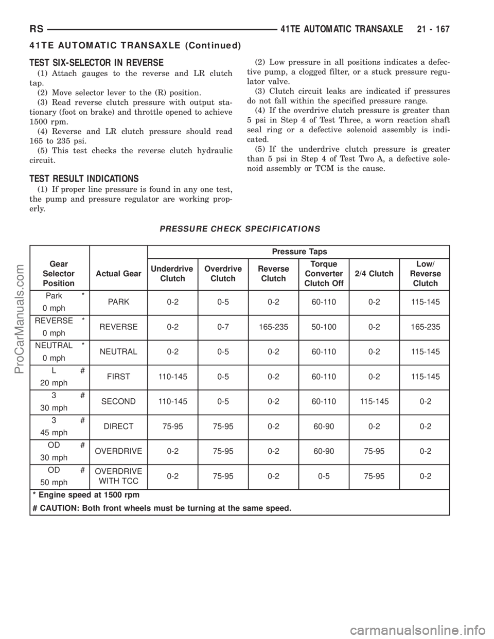
PRESSURE CHECK SPECIFICATIONS
Pressure Taps
Gear
Selector
PositionActual GearUnderdrive
ClutchOverdrive
ClutchReverse
ClutchTorque
Converter
Clutch Off2/4 ClutchLow/
Reverse
Clutch
Park *
PARK 0-2 0-5 0-2 60-110 0-2 115-145
0 mph
REVERSE *
REVERSE 0-2 0-7 165-235 50-100 0-2 165-235
0 mph
NEUTRAL *
NEUTRAL 0-2 0-5 0-2 60-110 0-2 115-145
0 mph
L#
FIRST 110-145 0-5 0-2 60-110 0-2 115-145
20 mph
3#
SECOND 110-145 0-5 0-2 60-110 115-145 0-2
30 mph
3#
DIRECT 75-95 75-95 0-2 60-90 0-2 0-2
45 mph
OD #
OVERDRIVE 0-2 75-95 0-2 60-90 75-95 0-2
30 mph
OD #
OVERDRIVE
WITH TCC0-2 75-95 0-2 0-5 75-95 0-2
50 mph
* Engine speed at 1500 rpm
# CAUTION: Both front wheels must be turning at the same speed.
RS41TE AUTOMATIC TRANSAXLE21 - 167
41TE AUTOMATIC TRANSAXLE (Continued)
ProCarManuals.com
Page 1806 of 2399
FLUID
STANDARD PROCEDURE
FLUID LEVEL AND CONDITION CHECK
NOTE: Only transmission fluid of the type labeled
Mopar ATF+4 (Automatic Transmission Fluid±Type
9602) should be used in this transaxle.
FLUID LEVEL CHECK
The transmission sump has a fluid level indicator
(dipstick) to check oil similar to most automatic
transmissions. It is located on the left side of the
engine. Be sure to wipe all dirt from dipstick handle
before removing.
The torque converter fills in both the P Park and N
Neutral positions. Place the selector lever in P Park
to be sure that the fluid level check is accurate.The
engine should be running at idle speed for at
least one minute, with the vehicle on level
ground.At normal operating temperature 82É C
(180É F), the fluid level is correct if it is in the HOT
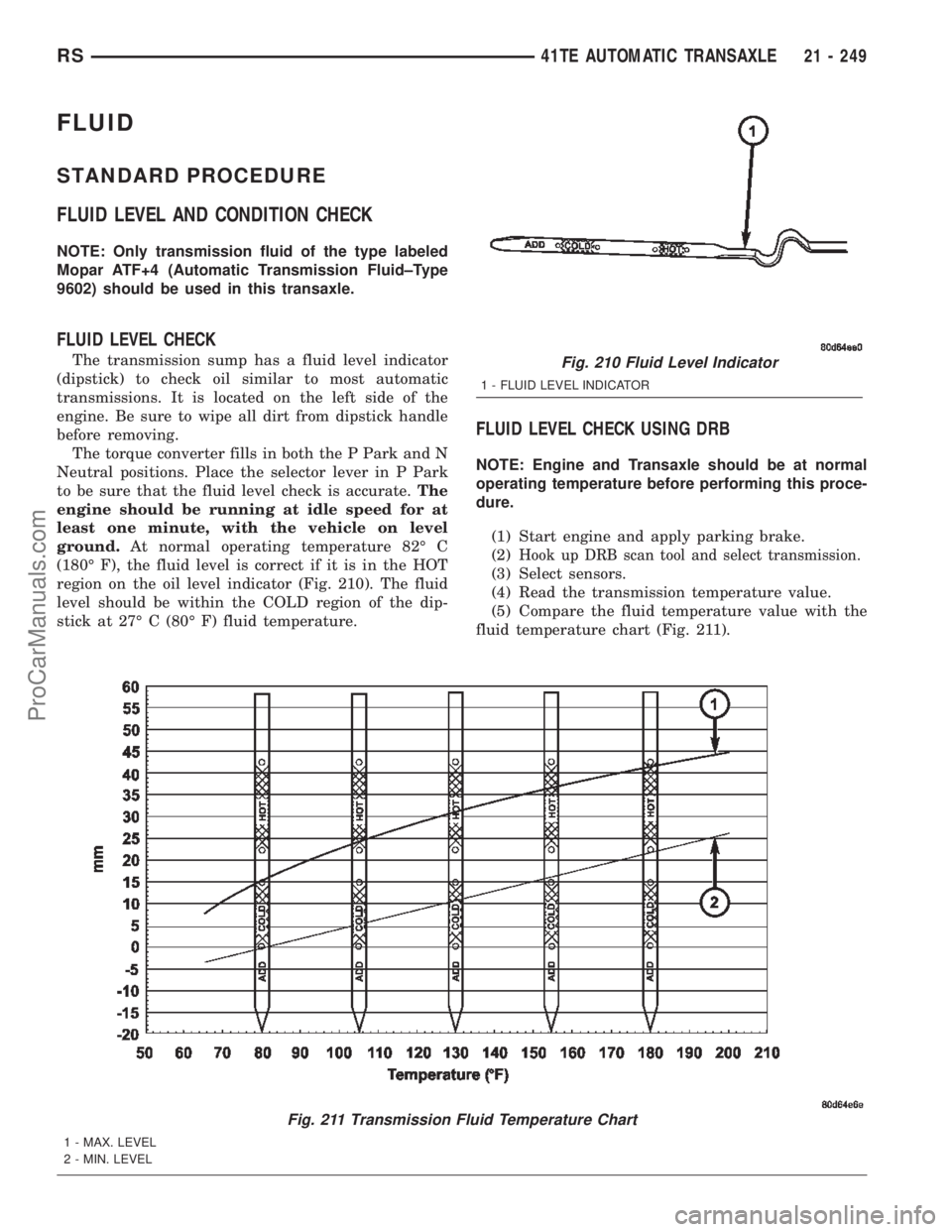
region on the oil level indicator (Fig. 210). The fluid
level should be within the COLD region of the dip-
stick at 27É C (80É F) fluid temperature.
FLUID LEVEL CHECK USING DRB
NOTE: Engine and Transaxle should be at normal
operating temperature before performing this proce-
dure.
(1) Start engine and apply parking brake.
(2)
Hook up DRB scan tool and select transmission.
(3) Select sensors.
(4) Read the transmission temperature value.
(5) Compare the fluid temperature value with the
fluid temperature chart (Fig. 211).
Fig. 210 Fluid Level Indicator
1 - FLUID LEVEL INDICATOR
Fig. 211 Transmission Fluid Temperature Chart
1 - MAX. LEVEL
2 - MIN. LEVEL
RS41TE AUTOMATIC TRANSAXLE21 - 249
ProCarManuals.com
Page 1807 of 2399
(6) Adjust transmission fluid level shown on the
indicator according to the chart.
(7) Check transmission for leaks.
Low fluid level can cause a variety of conditions
because it allows the pump to take in air along with
the fluid. As in any hydraulic system, air bubbles
make the fluid spongy, therefore, pressures will be
low and build up slowly.
Improper filling can also raise the fluid level too
high. When the transaxle has too much fluid, the
gears churn up foam and cause the same conditions
which occur with a low fluid level.
In either case, air bubbles can cause overheating
and/or fluid oxidation, and varnishing. This can
interfere with normal valve, clutch, and accumulator
operation. Foaming can also result in fluid escaping
from the transaxle vent where it may be mistaken
for a leak.
FLUID CONDITION
Along with fluid level, it is important to check the
condition of the fluid. When the fluid smells burned,
and is contaminated with metal or friction material
particles, a complete transaxle recondition is proba-
bly required. Be sure to examine the fluid on the dip-
stick closely. If there is any doubt about its condition,
drain out a sample for a double check.
MopartATF+4 (Automatic Transmission Fluid-
Type 9602) when new is red in color. The ATF is dyed
red so it can be identified from other fluids used in
the vehicle such as engine oil or antifreeze. The red
color is not permanent and is not an indicator of fluid
condition. As the vehicle is driven, the ATF will begin
to look darker in color and may eventually become
brown.This is normal.ATF+4 also has a unique
odor that may change with age. Consequently,odor
and color cannot be used to indicate the fluid
condition or the need for a fluid change.
After the fluid has been checked, seat the dipstick
fully to seal out water and dirt.
STANDARD PROCEDURE - FLUID AND FILTER
SERVICE
NOTE: Refer to the maintenance schedules in
LUBRICATION and MAINTENANCE, or the vehicle
owner's manual, for the recommended maintenance
(fluid/filter change) intervals for this transaxle.
NOTE: Only fluids of the type labeled MoparTATF+4
(Automatic Transmission Fluid) Type 9602 should
be used. A filter change should be made at the time
of the transmission oil change. The magnet (on the
inside of the oil pan) should also be cleaned with a
clean, dry cloth.NOTE: If the transaxle is disassembled for any rea-
son, the fluid and filter should be changed.
FLUID/FILTER SERVICE (RECOMMENDED)
(1) Raise vehicle on a hoist. Refer to LUBRICA-
TION and MAINTENANCE for proper procedures.
Place a drain container with a large opening, under
transaxle oil pan.
(2) Loosen pan bolts and tap the pan at one corner
to break it loose allowing fluid to drain, then remove
the oil pan.
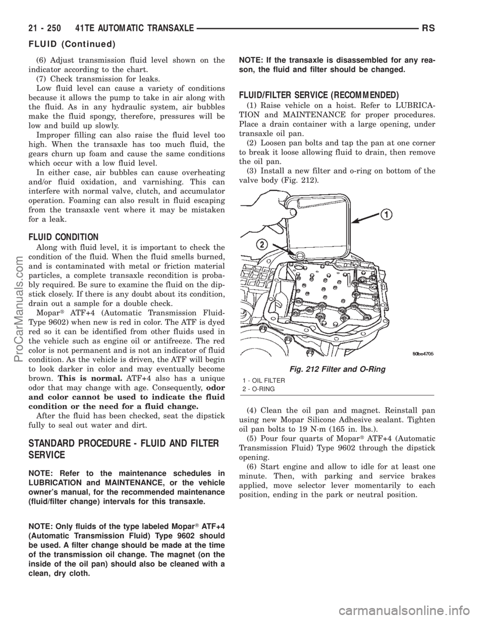
(3) Install a new filter and o-ring on bottom of the
valve body (Fig. 212).
(4) Clean the oil pan and magnet. Reinstall pan
using new Mopar Silicone Adhesive sealant. Tighten
oil pan bolts to 19 N´m (165 in. lbs.).
(5) Pour four quarts of MopartATF+4 (Automatic
Transmission Fluid) Type 9602 through the dipstick
opening.
(6) Start engine and allow to idle for at least one
minute. Then, with parking and service brakes
applied, move selector lever momentarily to each
position, ending in the park or neutral position.
Fig. 212 Filter and O-Ring
1 - OIL FILTER
2 - O-RING
21 - 250 41TE AUTOMATIC TRANSAXLERS
FLUID (Continued)
ProCarManuals.com
Page 1808 of 2399
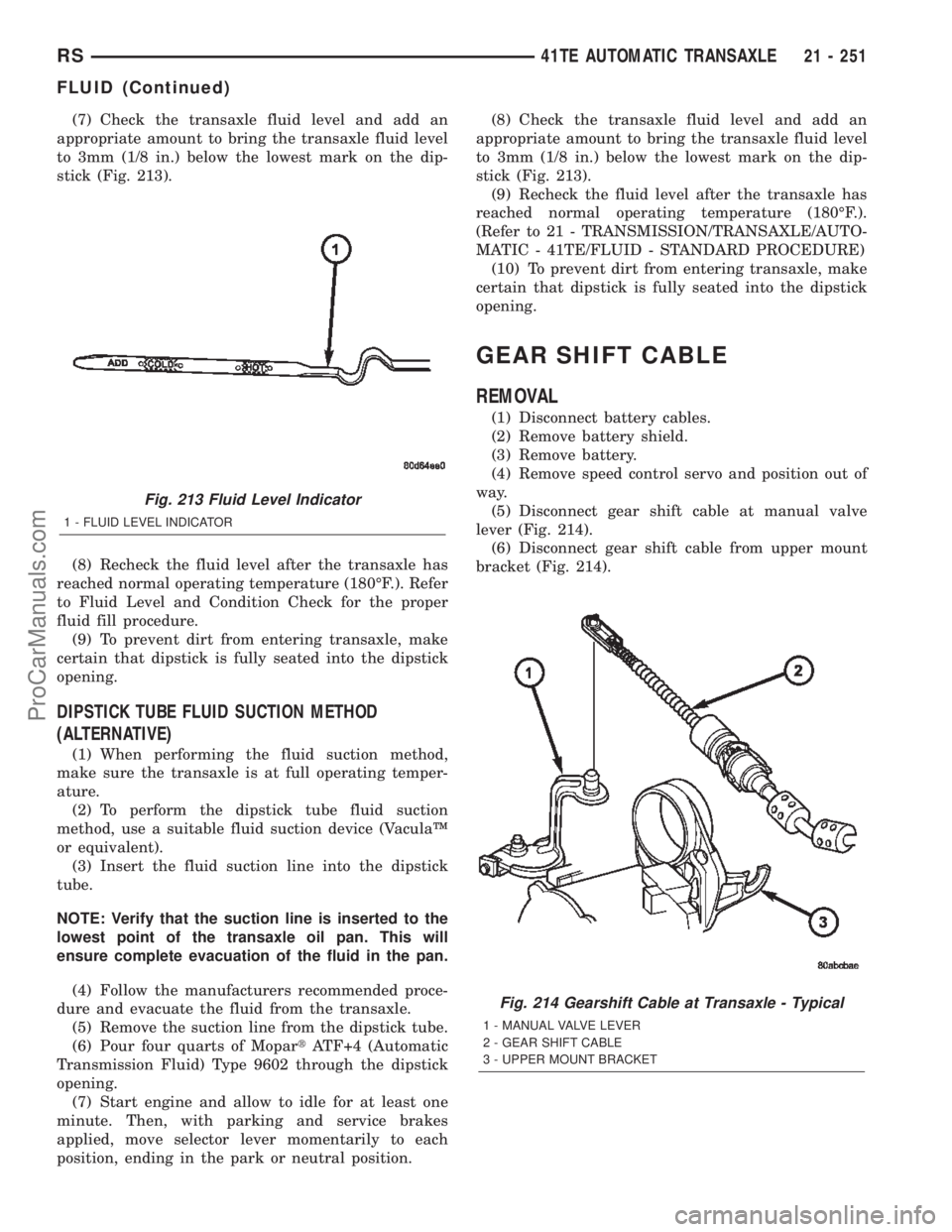
(7) Check the transaxle fluid level and add an
appropriate amount to bring the transaxle fluid level
to 3mm (1/8 in.) below the lowest mark on the dip-
stick (Fig. 213).
(8) Recheck the fluid level after the transaxle has
reached normal operating temperature (180ÉF.). Refer
to Fluid Level and Condition Check for the proper
fluid fill procedure.
(9) To prevent dirt from entering transaxle, make
certain that dipstick is fully seated into the dipstick
opening.
DIPSTICK TUBE FLUID SUCTION METHOD
(ALTERNATIVE)
(1) When performing the fluid suction method,
make sure the transaxle is at full operating temper-
ature.
(2) To perform the dipstick tube fluid suction
method, use a suitable fluid suction device (VaculaŸ
or equivalent).
(3) Insert the fluid suction line into the dipstick
tube.
NOTE: Verify that the suction line is inserted to the
lowest point of the transaxle oil pan. This will
ensure complete evacuation of the fluid in the pan.
(4) Follow the manufacturers recommended proce-
dure and evacuate the fluid from the transaxle.
(5) Remove the suction line from the dipstick tube.
(6) Pour four quarts of MopartATF+4 (Automatic
Transmission Fluid) Type 9602 through the dipstick
opening.
(7) Start engine and allow to idle for at least one
minute. Then, with parking and service brakes
applied, move selector lever momentarily to each
position, ending in the park or neutral position.(8) Check the transaxle fluid level and add an
appropriate amount to bring the transaxle fluid level
to 3mm (1/8 in.) below the lowest mark on the dip-
stick (Fig. 213).
(9) Recheck the fluid level after the transaxle has
reached normal operating temperature (180ÉF.).
(Refer to 21 - TRANSMISSION/TRANSAXLE/AUTO-
MATIC - 41TE/FLUID - STANDARD PROCEDURE)
(10) To prevent dirt from entering transaxle, make
certain that dipstick is fully seated into the dipstick
opening.
GEAR SHIFT CABLE
REMOVAL
(1) Disconnect battery cables.
(2) Remove battery shield.
(3) Remove battery.
(4) Remove speed control servo and position out of
way.
(5) Disconnect gear shift cable at manual valve
lever (Fig. 214).
(6) Disconnect gear shift cable from upper mount
bracket (Fig. 214).
Fig. 213 Fluid Level Indicator
1 - FLUID LEVEL INDICATOR
Fig. 214 Gearshift Cable at Transaxle - Typical
1 - MANUAL VALVE LEVER
2 - GEAR SHIFT CABLE
3 - UPPER MOUNT BRACKET
RS41TE AUTOMATIC TRANSAXLE21 - 251
FLUID (Continued)
ProCarManuals.com
Page 1811 of 2399
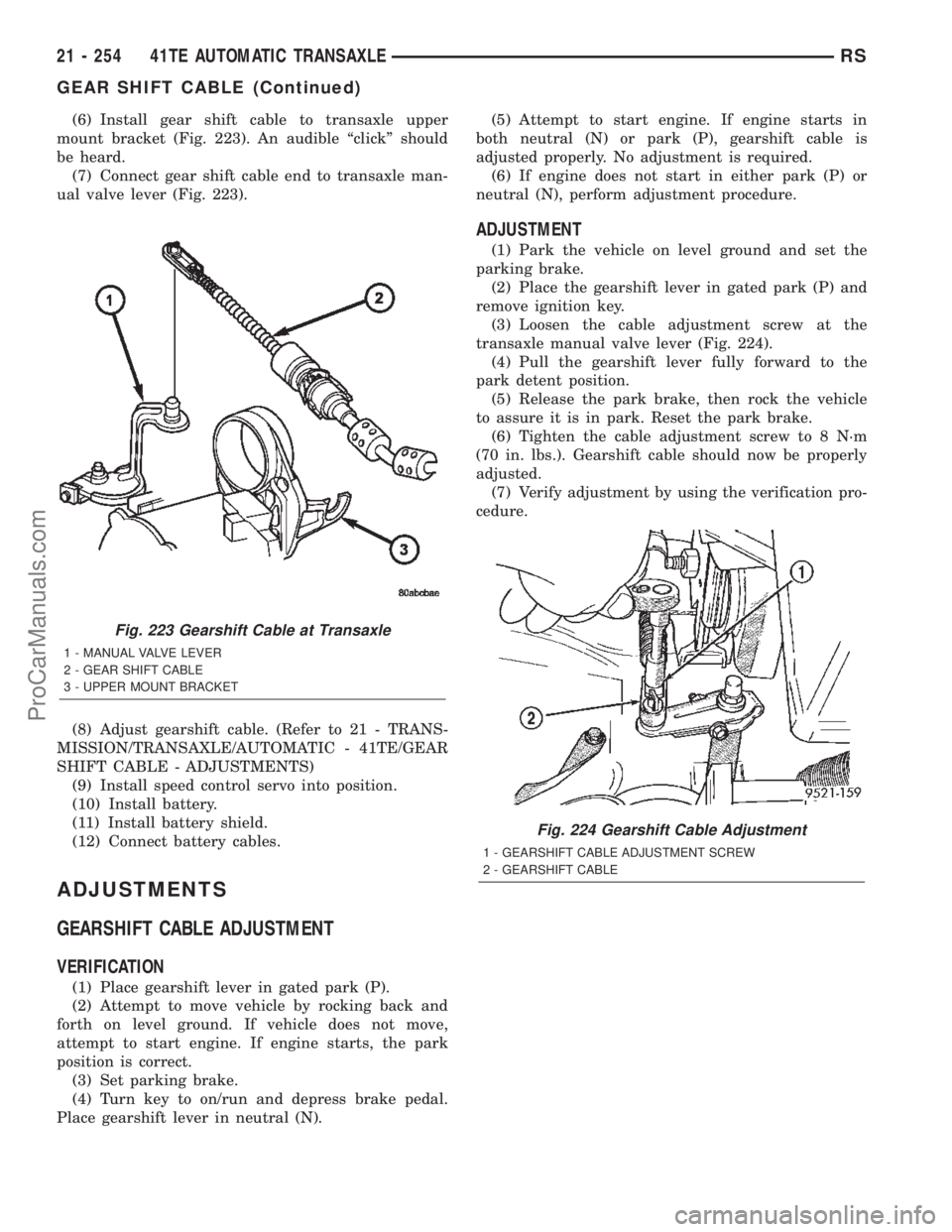
(6) Install gear shift cable to transaxle upper
mount bracket (Fig. 223). An audible ªclickº should
be heard.
(7) Connect gear shift cable end to transaxle man-
ual valve lever (Fig. 223).
(8) Adjust gearshift cable. (Refer to 21 - TRANS-
MISSION/TRANSAXLE/AUTOMATIC - 41TE/GEAR
SHIFT CABLE - ADJUSTMENTS)
(9) Install speed control servo into position.
(10) Install battery.
(11) Install battery shield.
(12) Connect battery cables.
ADJUSTMENTS
GEARSHIFT CABLE ADJUSTMENT
VERIFICATION
(1) Place gearshift lever in gated park (P).
(2) Attempt to move vehicle by rocking back and
forth on level ground. If vehicle does not move,
attempt to start engine. If engine starts, the park
position is correct.
(3) Set parking brake.
(4) Turn key to on/run and depress brake pedal.
Place gearshift lever in neutral (N).(5) Attempt to start engine. If engine starts in
both neutral (N) or park (P), gearshift cable is
adjusted properly. No adjustment is required.
(6) If engine does not start in either park (P) or
neutral (N), perform adjustment procedure.
ADJUSTMENT
(1) Park the vehicle on level ground and set the
parking brake.
(2) Place the gearshift lever in gated park (P) and
remove ignition key.
(3) Loosen the cable adjustment screw at the
transaxle manual valve lever (Fig. 224).
(4) Pull the gearshift lever fully forward to the
park detent position.
(5) Release the park brake, then rock the vehicle
to assure it is in park. Reset the park brake.
(6) Tighten the cable adjustment screw to 8 N´m
(70 in. lbs.). Gearshift cable should now be properly
adjusted.
(7) Verify adjustment by using the verification pro-
cedure.
Fig. 223 Gearshift Cable at Transaxle
1 - MANUAL VALVE LEVER
2 - GEAR SHIFT CABLE
3 - UPPER MOUNT BRACKET
Fig. 224 Gearshift Cable Adjustment
1 - GEARSHIFT CABLE ADJUSTMENT SCREW
2 - GEARSHIFT CABLE
21 - 254 41TE AUTOMATIC TRANSAXLERS
GEAR SHIFT CABLE (Continued)
ProCarManuals.com
Page 1832 of 2399
SEAL - OIL PUMP
REMOVAL
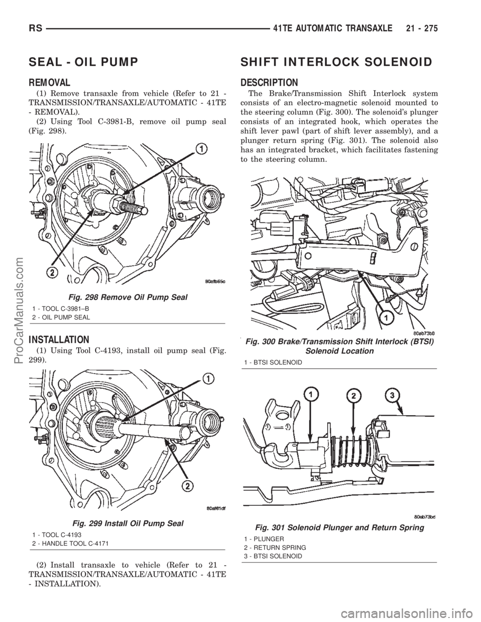
(1) Remove transaxle from vehicle (Refer to 21 -
TRANSMISSION/TRANSAXLE/AUTOMATIC - 41TE
- REMOVAL).
(2) Using Tool C-3981-B, remove oil pump seal
(Fig. 298).
INSTALLATION
(1) Using Tool C-4193, install oil pump seal (Fig.
299).
(2) Install transaxle to vehicle (Refer to 21 -
TRANSMISSION/TRANSAXLE/AUTOMATIC - 41TE
- INSTALLATION).
SHIFT INTERLOCK SOLENOID
DESCRIPTION
The Brake/Transmission Shift Interlock system
consists of an electro-magnetic solenoid mounted to
the steering column (Fig. 300). The solenoid's plunger
consists of an integrated hook, which operates the
shift lever pawl (part of shift lever assembly), and a
plunger return spring (Fig. 301). The solenoid also
has an integrated bracket, which facilitates fastening
to the steering column.
Fig. 298 Remove Oil Pump Seal
1 - TOOL C-3981±B
2 - OIL PUMP SEAL
Fig. 299 Install Oil Pump Seal
1 - TOOL C-4193
2 - HANDLE TOOL C-4171
Fig. 300 Brake/Transmission Shift Interlock (BTSI)
Solenoid Location
1 - BTSI SOLENOID
Fig. 301 Solenoid Plunger and Return Spring
1 - PLUNGER
2 - RETURN SPRING
3 - BTSI SOLENOID
RS41TE AUTOMATIC TRANSAXLE21 - 275
ProCarManuals.com