2002 CHRYSLER VOYAGER air conditioning
[x] Cancel search: air conditioningPage 868 of 2399

8W-42 AIR CONDITIONING-HEATER
Component Page
A/C Compressor Clutch............ 8W-42-14, 16
A/C Compressor Clutch Relay....... 8W-42-14, 16
A/C Pressure Sensor.............. 8W-42-14, 16
A/C- Heater Control.......... 8W-42-2, 3, 4, 5, 7
ATC Remote Sensor................. 8W-42-11
Auto Temp Control...... 8W-42-8, 9, 10, 11, 12, 13
Battery........................... 8W-42-17
Blower Motor Resistor................ 8W-42-2
Body Control Module........... 8W-42-4, 7, 9, 13
Diagnostic Junction Port............. 8W-42-4, 9
Driver Blend Door Actuator......... 8W-42-5, 10
ECM/PCM Relay.................... 8W-42-17
Electric Wiper De-Icer............... 8W-42-3, 8
Engine Control Module............ 8W-42-16, 17
Evaporator Temperature Sensor...... 8W-42-5, 10
Front Blower Module................ 8W-42-11
Front Blower Motor................ 8W-42-2, 11
Front Blower Motor Relay........... 8W-42-2, 11
Front Control Module......... 8W-42-2, 6, 11, 12
Fuse 10......................... 8W-42-2, 11
Fuse 12......................... 8W-42-6, 12
Fuse 14............................ 8W-42-8
Fuse 16........................... 8W-42-17
Fuse 18........................ 8W-42-14, 16
Fuse 27........................ 8W-42-15, 18
Fuselink.......................... 8W-42-17
G102.......................... 8W-42-15, 18Component Page
G103.......................... 8W-42-14, 16
G200.............. 8W-42-2, 3, 4, 6, 8, 9, 11, 12
G300........................... 8W-42-7, 13
G302............................. 8W-42-12
Integrated Power
Module . . 8W-42-2, 6, 8, 11, 12, 14, 15, 16, 17, 18
Mode Door Actuator............... 8W-42-5, 10
Passenger Blend Door Actuator....... 8W-42-5, 10
Powertrain Control Module......... 8W-42-14, 15
Radiator Fan No. 1............ 8W-42-15, 17, 18
Radiator Fan No. 2............... 8W-42-15, 18
Radiator Fan Relay.................. 8W-42-15
Radiator Fan Relay No. 1.......... 8W-42-17, 18
Radiator Fan Relay No. 2............. 8W-42-18
Radiator Fan Relay No. 3............. 8W-42-18
Rear A/C-Heater Unit............... 8W-42-6, 7
Rear Auto Temp Control Switch........ 8W-42-13
Rear Blower Front Control Switch....... 8W-42-6
Rear Blower Motor.................. 8W-42-12
Rear Blower Motor Power Module...... 8W-42-12
Rear Blower Motor Relay........... 8W-42-6, 12
Rear Blower Rear Control Switch...... 8W-42-6, 7
Rear Mode Motor................... 8W-42-12
Rear Temperature Motor.............. 8W-42-12
Recirculation Door Actuator......... 8W-42-5, 10
TXV Solenoid...................... 8W-42-12
RS8W-42 AIR CONDITIONING-HEATER8W-42-1
ProCarManuals.com
Page 1214 of 2399
NOTE: When the transaxle cooler lines are removed
from the rolled-groove type fittings at the transaxle,
damage to the inner wall of the hose will occur. To
prevent prevent potential leakage, the cooler hoses
must be cut off flush at the transaxle fitting, and a
service cooler hose splice kit must be installed
upon reassembly.
(9) Using a blade or suitable hose cutter, cut trans-
axle oil cooler lines off flush with fittings. Plug cooler
lines and fittings to prevent debris from entering
transaxle or cooler circuit. A service splice kit will be
installed upon reassembly.
(10) Disconnect transmission shift linkage and
electrical connectors.
(11) Disconnect throttle body linkage.
(12) Disconnect engine wiring harness.
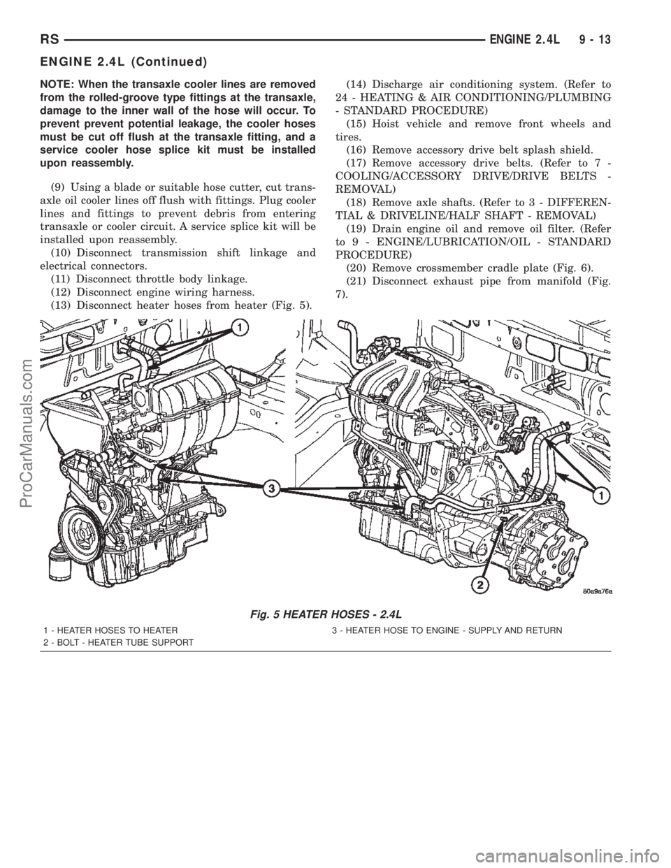
(13) Disconnect heater hoses from heater (Fig. 5).(14) Discharge air conditioning system. (Refer to
24 - HEATING & AIR CONDITIONING/PLUMBING
- STANDARD PROCEDURE)
(15) Hoist vehicle and remove front wheels and
tires.
(16) Remove accessory drive belt splash shield.
(17) Remove accessory drive belts. (Refer to 7 -
COOLING/ACCESSORY DRIVE/DRIVE BELTS -
REMOVAL)
(18) Remove axle shafts. (Refer to 3 - DIFFEREN-
TIAL & DRIVELINE/HALF SHAFT - REMOVAL)
(19) Drain engine oil and remove oil filter. (Refer
to 9 - ENGINE/LUBRICATION/OIL - STANDARD
PROCEDURE)
(20) Remove crossmember cradle plate (Fig. 6).
(21) Disconnect exhaust pipe from manifold (Fig.
7).
Fig. 5 HEATER HOSES - 2.4L
1 - HEATER HOSES TO HEATER 3 - HEATER HOSE TO ENGINE - SUPPLY AND RETURN
2 - BOLT - HEATER TUBE SUPPORT
RSENGINE 2.4L9-13
ENGINE 2.4L (Continued)
ProCarManuals.com
Page 1234 of 2399
REMOVAL - CYLINDER HEAD OFF
(1) With cylinder head removed from cylinder
block, compress valve springs using a universal valve
spring compressor.
(2) Remove valve retaining locks, valve spring
retainers, valve stem seals and valve springs.
(3) Before removing valves,remove any burrs
from valve stem lock grooves to prevent dam-
age to the valve guides.Identify valves, locks and
retainers to insure installation in original location.
(4) Inspect the valves. (Refer to 9 - ENGINE/CYL-
INDER HEAD/VALVE SPRINGS - INSPECTION)
INSPECTION
(1) Whenever valves have been removed for inspec-
tion, reconditioning or replacement, valve springs
should be tested for correct tension. Discard the
springs that do not meet specifications. The following
specifications apply to both intake and exhaust
valves springs:
²Valve Closed Nominal TensionÐ76 lbs. @ 38.0
mm (1.50 in.)
²Valve Open Nominal TensionÐ136 lbs. @ 29.75
mm (1.17 in.)
(2) Inspect each valve spring for squareness with a
steel square and surface plate, test springs from both
ends. If the spring is more than 1.5 mm (1/16 inch)
out of square, install a new spring.
INSTALLATION
INSTALLATION - CYLINDER HEAD ON
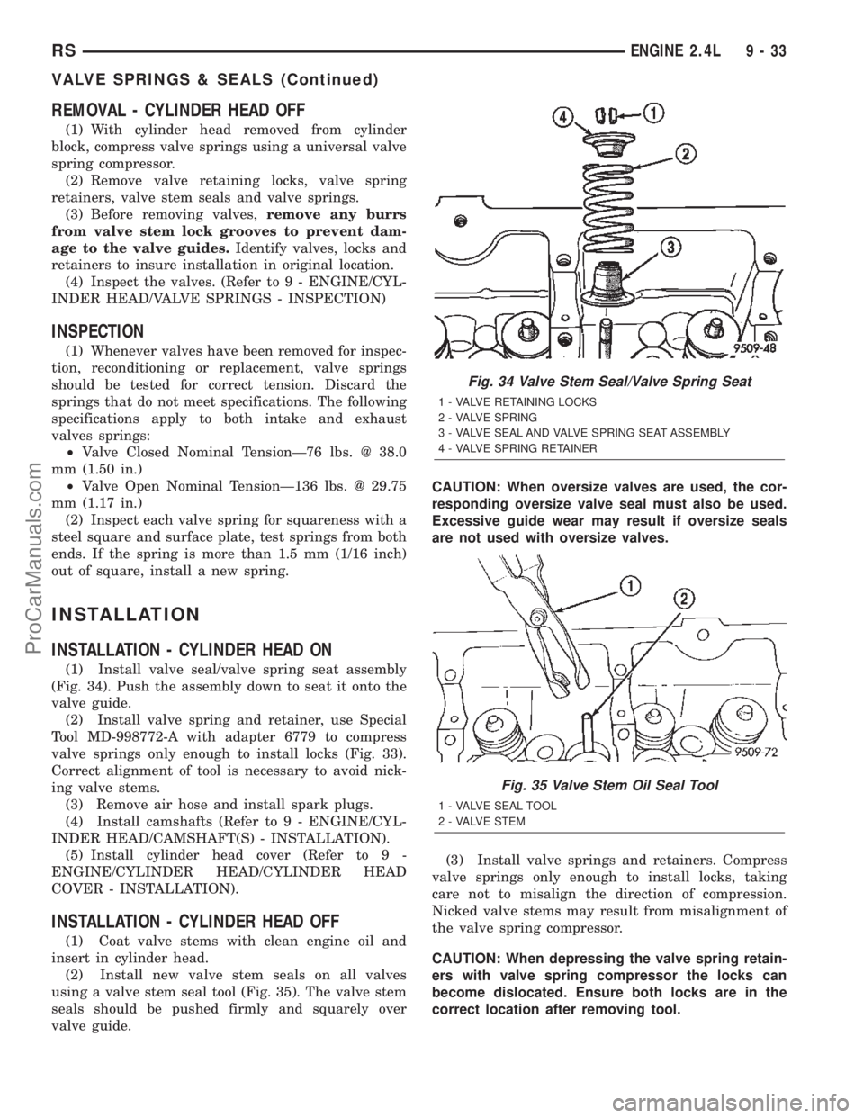
(1) Install valve seal/valve spring seat assembly
(Fig. 34). Push the assembly down to seat it onto the
valve guide.
(2) Install valve spring and retainer, use Special
Tool MD-998772-A with adapter 6779 to compress
valve springs only enough to install locks (Fig. 33).
Correct alignment of tool is necessary to avoid nick-
ing valve stems.
(3) Remove air hose and install spark plugs.
(4) Install camshafts (Refer to 9 - ENGINE/CYL-
INDER HEAD/CAMSHAFT(S) - INSTALLATION).
(5) Install cylinder head cover (Refer to 9 -
ENGINE/CYLINDER HEAD/CYLINDER HEAD
COVER - INSTALLATION).
INSTALLATION - CYLINDER HEAD OFF
(1) Coat valve stems with clean engine oil and
insert in cylinder head.
(2) Install new valve stem seals on all valves
using a valve stem seal tool (Fig. 35). The valve stem
seals should be pushed firmly and squarely over
valve guide.CAUTION: When oversize valves are used, the cor-
responding oversize valve seal must also be used.
Excessive guide wear may result if oversize seals
are not used with oversize valves.
(3) Install valve springs and retainers. Compress
valve springs only enough to install locks, taking
care not to misalign the direction of compression.
Nicked valve stems may result from misalignment of
the valve spring compressor.
CAUTION: When depressing the valve spring retain-
ers with valve spring compressor the locks can
become dislocated. Ensure both locks are in the
correct location after removing tool.
Fig. 34 Valve Stem Seal/Valve Spring Seat
1 - VALVE RETAINING LOCKS
2 - VALVE SPRING
3 - VALVE SEAL AND VALVE SPRING SEAT ASSEMBLY
4 - VALVE SPRING RETAINER
Fig. 35 Valve Stem Oil Seal Tool
1 - VALVE SEAL TOOL
2 - VALVE STEM
RSENGINE 2.4L9-33
VALVE SPRINGS & SEALS (Continued)
ProCarManuals.com
Page 1256 of 2399
INSTALLATION
(1) Clean and check filter mounting surface. The
surface must be smooth, flat and free of debris or
pieces of gasket.
(2) Lubricate new oil filter gasket with clean
engine oil.
(3) Screw oil filter (Fig. 88) on until the gasket
contacts base. Tighten to 12 N´m (105 in. lbs.).
OIL PAN
REMOVAL
(1) Raise vehicle on hoist and drain engine oil.
(2) Remove structural collar. (Refer to 9 -
ENGINE/ENGINE BLOCK/STRUCTURAL COVER -
REMOVAL)
(3) Remove air conditioning compressor bracket to
oil pan bolt.
(4) Remove bolts attaching oil pan.
(5) Remove oil pan.
(6) Clean oil pan and all gasket surfaces.
INSTALLATION
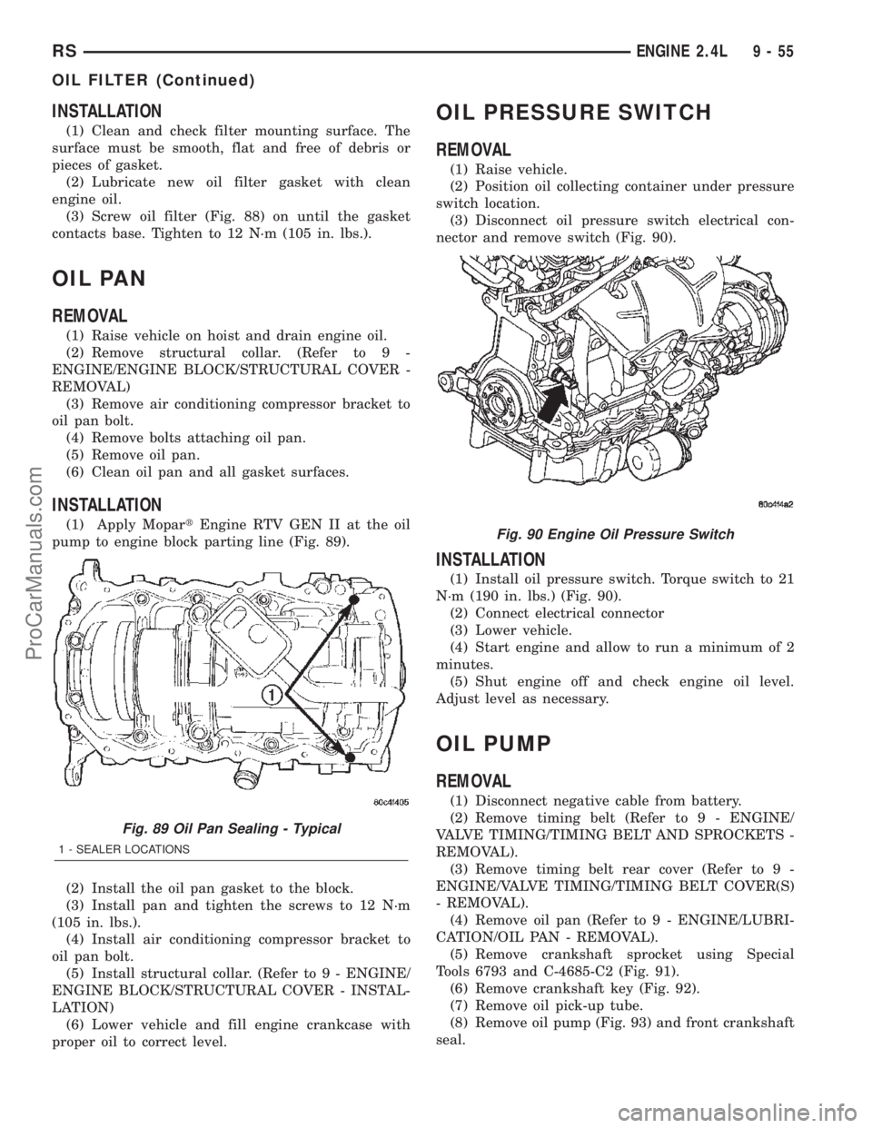
(1) Apply MopartEngine RTV GEN II at the oil
pump to engine block parting line (Fig. 89).
(2) Install the oil pan gasket to the block.
(3) Install pan and tighten the screws to 12 N´m
(105 in. lbs.).
(4) Install air conditioning compressor bracket to
oil pan bolt.
(5) Install structural collar. (Refer to 9 - ENGINE/
ENGINE BLOCK/STRUCTURAL COVER - INSTAL-
LATION)
(6) Lower vehicle and fill engine crankcase with
proper oil to correct level.
OIL PRESSURE SWITCH
REMOVAL
(1) Raise vehicle.
(2) Position oil collecting container under pressure
switch location.
(3) Disconnect oil pressure switch electrical con-
nector and remove switch (Fig. 90).
INSTALLATION
(1) Install oil pressure switch. Torque switch to 21
N´m (190 in. lbs.) (Fig. 90).
(2) Connect electrical connector
(3) Lower vehicle.
(4) Start engine and allow to run a minimum of 2
minutes.
(5) Shut engine off and check engine oil level.
Adjust level as necessary.
OIL PUMP
REMOVAL
(1) Disconnect negative cable from battery.
(2) Remove timing belt (Refer to 9 - ENGINE/
VALVE TIMING/TIMING BELT AND SPROCKETS -
REMOVAL).
(3) Remove timing belt rear cover (Refer to 9 -
ENGINE/VALVE TIMING/TIMING BELT COVER(S)
- REMOVAL).
(4) Remove oil pan (Refer to 9 - ENGINE/LUBRI-
CATION/OIL PAN - REMOVAL).
(5) Remove crankshaft sprocket using Special
Tools 6793 and C-4685-C2 (Fig. 91).
(6) Remove crankshaft key (Fig. 92).
(7) Remove oil pick-up tube.
(8) Remove oil pump (Fig. 93) and front crankshaft
seal.
Fig. 89 Oil Pan Sealing - Typical
1 - SEALER LOCATIONS
Fig. 90 Engine Oil Pressure Switch
RSENGINE 2.4L9-55
OIL FILTER (Continued)
ProCarManuals.com
Page 1269 of 2399
(5) Remove the pull pin or Allen wrench from the
belt tensioner.
(6) Once the timing belt has been installed and
tensioner released, rotate the crankshaft two (2) com-
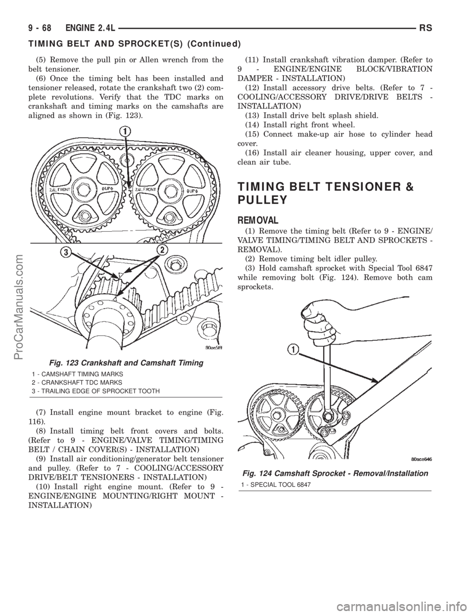
plete revolutions. Verify that the TDC marks on
crankshaft and timing marks on the camshafts are
aligned as shown in (Fig. 123).
(7) Install engine mount bracket to engine (Fig.
116).
(8) Install timing belt front covers and bolts.
(Refer to 9 - ENGINE/VALVE TIMING/TIMING
BELT / CHAIN COVER(S) - INSTALLATION)
(9) Install air conditioning/generator belt tensioner
and pulley. (Refer to 7 - COOLING/ACCESSORY
DRIVE/BELT TENSIONERS - INSTALLATION)
(10) Install right engine mount. (Refer to 9 -
ENGINE/ENGINE MOUNTING/RIGHT MOUNT -
INSTALLATION)(11) Install crankshaft vibration damper. (Refer to
9 - ENGINE/ENGINE BLOCK/VIBRATION
DAMPER - INSTALLATION)
(12) Install accessory drive belts. (Refer to 7 -
COOLING/ACCESSORY DRIVE/DRIVE BELTS -
INSTALLATION)
(13) Install drive belt splash shield.
(14) Install right front wheel.
(15) Connect make-up air hose to cylinder head
cover.
(16) Install air cleaner housing, upper cover, and
clean air tube.
TIMING BELT TENSIONER &
PULLEY
REMOVAL
(1) Remove the timing belt (Refer to 9 - ENGINE/
VALVE TIMING/TIMING BELT AND SPROCKETS -
REMOVAL).
(2) Remove timing belt idler pulley.
(3) Hold camshaft sprocket with Special Tool 6847
while removing bolt (Fig. 124). Remove both cam
sprockets.
Fig. 123 Crankshaft and Camshaft Timing
1 - CAMSHAFT TIMING MARKS
2 - CRANKSHAFT TDC MARKS
3 - TRAILING EDGE OF SPROCKET TOOTH
Fig. 124 Camshaft Sprocket - Removal/Installation
1 - SPECIAL TOOL 6847
9 - 68 ENGINE 2.4LRS
TIMING BELT AND SPROCKET(S) (Continued)
ProCarManuals.com
Page 1288 of 2399
REMOVAL - ENGINE ASSEMBLY
(1) Perform fuel pressure release procedure (Refer
to 14 - FUEL SYSTEM/FUEL DELIVERY - STAN-
DARD PROCEDURE).
(2) Disconnect negative battery cable.
(3) Remove air cleaner and hoses.
(4) Disconnect the fuel line from fuel rail (Refer to
14 - FUEL SYSTEM/FUEL DELIVERY/QUICK
CONNECT FITTING - STANDARD PROCEDURE).
(5) Remove the wiper module (Refer to 8 - ELEC-
TRICAL/WIPERS/WASHERS/WIPER MODULE -
REMOVAL).
(6) Block off heater hoses to the rear heater sys-
tem using pinch-off pliers (if equipped).
(7) Drain the cooling system (Refer to 7 - COOL-
ING - STANDARD PROCEDURE).
(8) Disconnect the heater hoses.
(9) Remove the radiator upper support crossmem-
ber (Refer to 23 - BODY/EXTERIOR/GRILLE OPEN-
ING REINFORCEMENT - REMOVAL).
(10) Remove the radiator fans (Refer to 7 - COOL-
ING/ENGINE/RADIATOR FAN - REMOVAL).
(11) Disconnect the throttle cables from the throt-
tle body.
(12) Disconnect the MAP, IAC, and TPS electrical
connectors.
(13) Disconnect the EGR transducer electrical con-
nector (if equipped).
(14) Disconnect the vacuum hoses from throttle
body.
(15) Disconnect the brake booster and speed con-
trol vacuum hoses.
(16) Disengage wire harness clip from the right
side engine mount.
(17) Remove the power steering reservoir from
mounting position and set aside.Do notdisconnect
hose.
(18) Disconnect ground strap from rear of cylinder
head.
(19) Disconnect engine coolant temperature (ECT)
sensor and ignition coil electrical connectors.
(20) Disconnect the fuel injector electrical harness
connector and disengage clip from support bracket.
(21) Disconnect camshaft and crankshaft position
sensor electrical connectors.
(22) Evacuate air conditioning system. Refer to 24
- HEATING & AIR CONDITIONING.
(23) Disconnect A/C compressor electrical connec-
tor.(24) Disconnect the A/C lines from compressor.
Cover and seal all openings of hoses and compressor.
(25) Remove the radiator upper hose.
(26) Disengage electrical harness clip at transaxle
dipstick tube.
(27) Remove transaxle dipstick tube. Seal opening
using a suitable plug.
NOTE: When the transaxle cooler lines are removed
from the rolled-groove type fittings at the transaxle,
damage to the inner wall of the hose will occur. To
prevent prevent potential leakage, the cooler hoses
must be cut off flush at the transaxle fitting, and a
service cooler hose splice kit must be installed
upon reassembly.
(28) Using a blade or suitable hose cutter, cut
transaxle oil cooler lines off flush with fittings. Plug
cooler lines and fittings to prevent debris from enter-
ing transaxle or cooler circuit. A service splice kit will
be installed upon reassembly.
(29) Disconnect transaxle shift linkage and electri-
cal connectors.
(30) Raise vehicle on hoist and drain the engine
oil.
(31) Remove the axle shafts. (Refer to 3 - DIFFER-
ENTIAL & DRIVELINE/HALF SHAFT - REMOVAL)
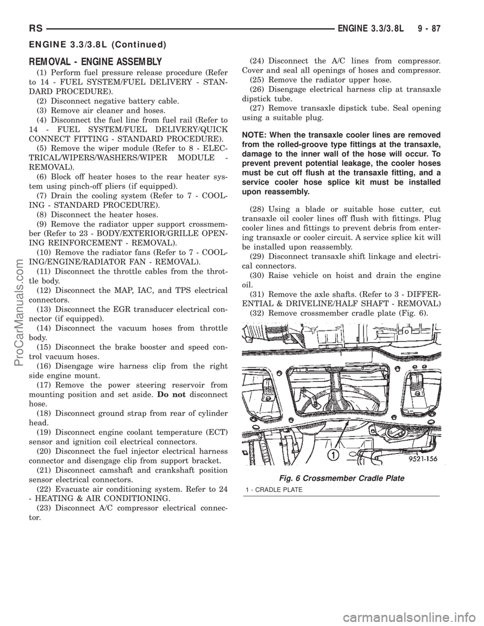
(32) Remove crossmember cradle plate (Fig. 6).
Fig. 6 Crossmember Cradle Plate
1 - CRADLE PLATE
RSENGINE 3.3/3.8L9-87
ENGINE 3.3/3.8L (Continued)
ProCarManuals.com
Page 1289 of 2399
(33)AWD equipped:Remove the power transfer
unit (PTU) (Refer to 21 - TRANSMISSION/TRANS-
AXLE/POWER TRANSFER UNIT - REMOVAL).
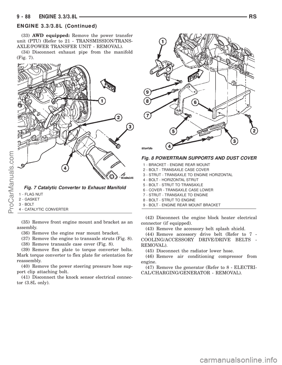
(34) Disconnect exhaust pipe from the manifold
(Fig. 7).
(35) Remove front engine mount and bracket as an
assembly.
(36) Remove the engine rear mount bracket.
(37) Remove the engine to transaxle struts (Fig. 8).
(38) Remove transaxle case cover (Fig. 8).
(39) Remove flex plate to torque converter bolts.
Mark torque converter to flex plate for orientation for
reassembly.
(40) Remove the power steering pressure hose sup-
port clip attaching bolt.
(41) Disconnect the knock sensor electrical connec-
tor (3.8L only).(42) Disconnect the engine block heater electrical
connector (if equipped).
(43) Remove the accessory belt splash shield.
(44) Remove accessory drive belt (Refer to 7 -
COOLING/ACCESSORY DRIVE/DRIVE BELTS -
REMOVAL).
(45) Disconnect the radiator lower hose.
(46) Remove air conditioning compressor from
engine.
(47) Remove the generator (Refer to 8 - ELECTRI-
CAL/CHARGING/GENERATOR - REMOVAL).
Fig. 7 Catalytic Converter to Exhaust Manifold
1 - FLAG NUT
2 - GASKET
3 - BOLT
4 - CATALYTIC CONVERTER
Fig. 8 POWERTRAIN SUPPORTS AND DUST COVER
1 - BRACKET - ENGINE REAR MOUNT
2 - BOLT - TRANSAXLE CASE COVER
3 - STRUT - TRANSAXLE TO ENGINE HORIZONTAL
4 - BOLT - HORIZONTAL STRUT
5 - BOLT - STRUT TO TRANSAXLE
6 - COVER - TRANSAXLE CASE LOWER
7 - STRUT - TRANSAXLE TO ENGINE
8 - BOLT - STRUT TO ENGINE
9 - BOLT - ENGINE REAR MOUNT BRACKET
9 - 88 ENGINE 3.3/3.8LRS
ENGINE 3.3/3.8L (Continued)
ProCarManuals.com
Page 1310 of 2399
(11) Repeat procedure for each cylinder requiring
valve spring removal.
INSPECTION
Whenever valves have been removed for inspection,
reconditioning or replacement, valve springs should
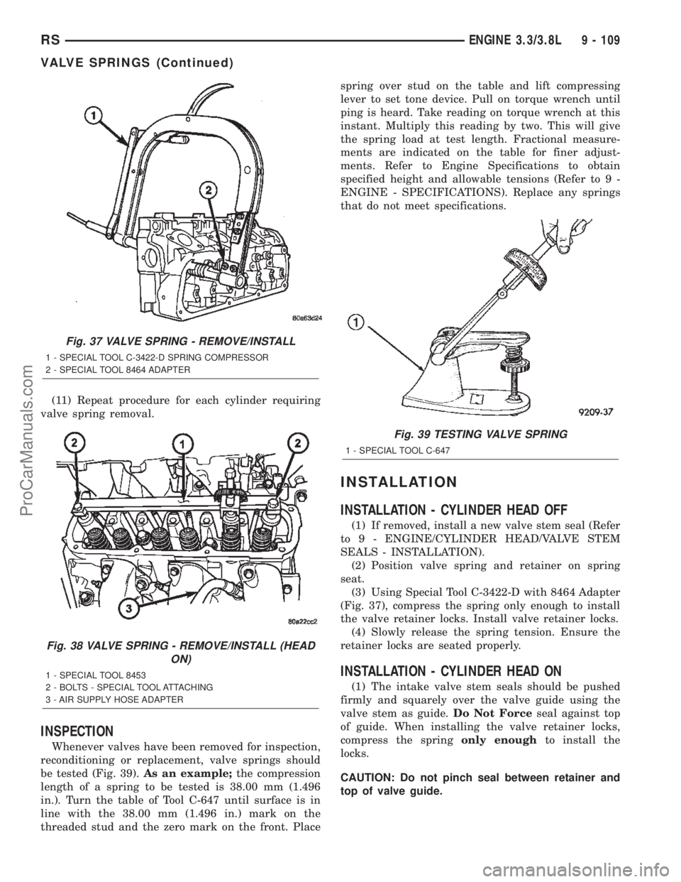
be tested (Fig. 39).As an example;the compression
length of a spring to be tested is 38.00 mm (1.496
in.). Turn the table of Tool C-647 until surface is in
line with the 38.00 mm (1.496 in.) mark on the
threaded stud and the zero mark on the front. Placespring over stud on the table and lift compressing
lever to set tone device. Pull on torque wrench until
ping is heard. Take reading on torque wrench at this
instant. Multiply this reading by two. This will give
the spring load at test length. Fractional measure-
ments are indicated on the table for finer adjust-
ments. Refer to Engine Specifications to obtain
specified height and allowable tensions (Refer to 9 -
ENGINE - SPECIFICATIONS). Replace any springs
that do not meet specifications.
INSTALLATION
INSTALLATION - CYLINDER HEAD OFF
(1) If removed, install a new valve stem seal (Refer
to 9 - ENGINE/CYLINDER HEAD/VALVE STEM
SEALS - INSTALLATION).
(2) Position valve spring and retainer on spring
seat.
(3) Using Special Tool C-3422-D with 8464 Adapter
(Fig. 37), compress the spring only enough to install
the valve retainer locks. Install valve retainer locks.
(4) Slowly release the spring tension. Ensure the
retainer locks are seated properly.
INSTALLATION - CYLINDER HEAD ON
(1) The intake valve stem seals should be pushed
firmly and squarely over the valve guide using the
valve stem as guide.Do Not Forceseal against top
of guide. When installing the valve retainer locks,
compress the springonly enoughto install the
locks.
CAUTION: Do not pinch seal between retainer and
top of valve guide.
Fig. 37 VALVE SPRING - REMOVE/INSTALL
1 - SPECIAL TOOL C-3422-D SPRING COMPRESSOR
2 - SPECIAL TOOL 8464 ADAPTER
Fig. 38 VALVE SPRING - REMOVE/INSTALL (HEAD
ON)
1 - SPECIAL TOOL 8453
2 - BOLTS - SPECIAL TOOL ATTACHING
3 - AIR SUPPLY HOSE ADAPTER
Fig. 39 TESTING VALVE SPRING
1 - SPECIAL TOOL C-647
RSENGINE 3.3/3.8L9 - 109
VALVE SPRINGS (Continued)
ProCarManuals.com