2002 CHRYSLER VOYAGER roof rack
[x] Cancel search: roof rackPage 2109 of 2399
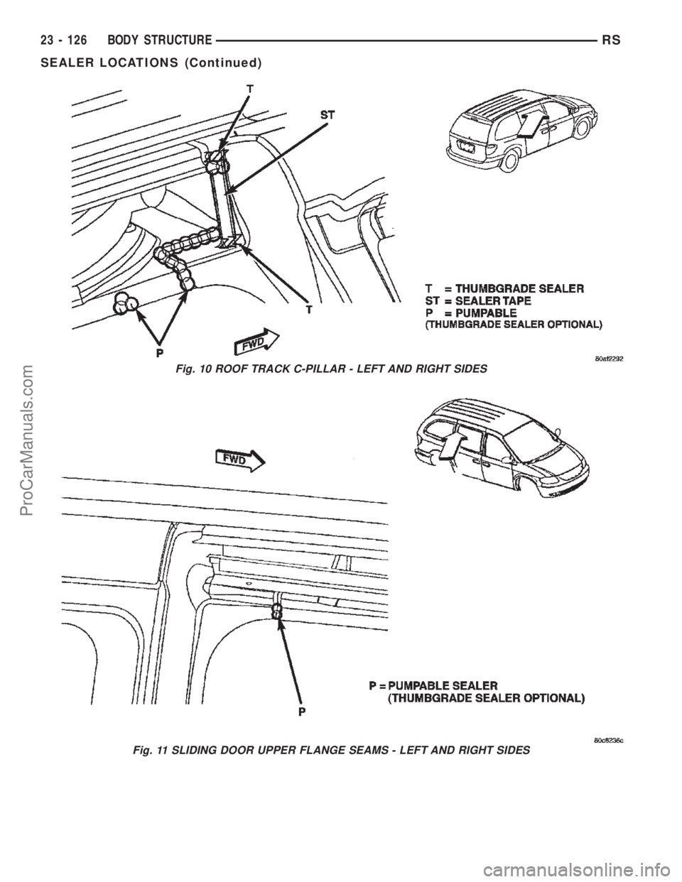
Fig. 10 ROOF TRACK C-PILLAR - LEFT AND RIGHT SIDES
Fig. 11 SLIDING DOOR UPPER FLANGE SEAMS - LEFT AND RIGHT SIDES
23 - 126 BODY STRUCTURERS
SEALER LOCATIONS (Continued)
ProCarManuals.com
Page 2130 of 2399
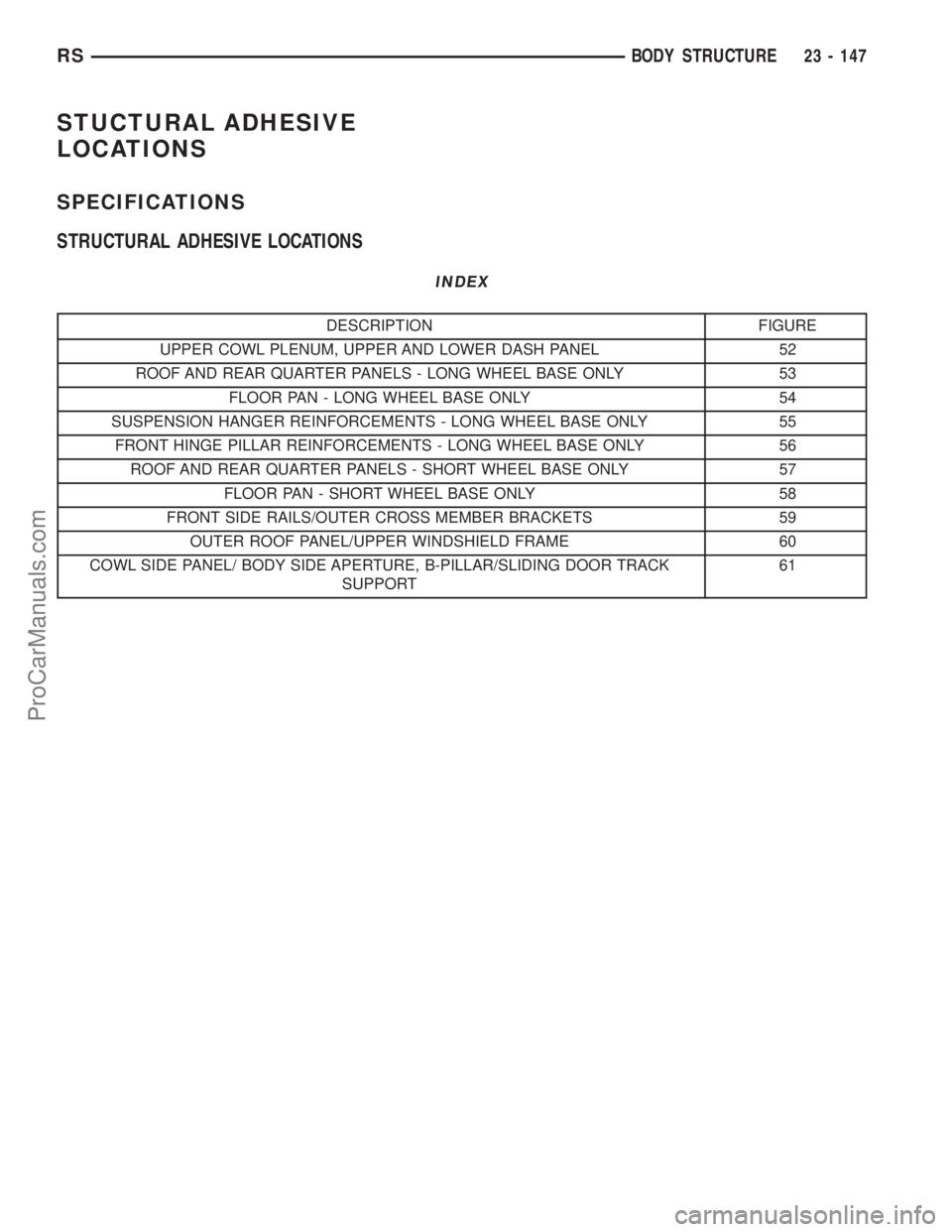
STUCTURAL ADHESIVE
LOCATIONS
SPECIFICATIONS
STRUCTURAL ADHESIVE LOCATIONS
INDEX
DESCRIPTION FIGURE
UPPER COWL PLENUM, UPPER AND LOWER DASH PANEL 52
ROOF AND REAR QUARTER PANELS - LONG WHEEL BASE ONLY 53
FLOOR PAN - LONG WHEEL BASE ONLY 54
SUSPENSION HANGER REINFORCEMENTS - LONG WHEEL BASE ONLY 55
FRONT HINGE PILLAR REINFORCEMENTS - LONG WHEEL BASE ONLY 56
ROOF AND REAR QUARTER PANELS - SHORT WHEEL BASE ONLY 57
FLOOR PAN - SHORT WHEEL BASE ONLY 58
FRONT SIDE RAILS/OUTER CROSS MEMBER BRACKETS 59
OUTER ROOF PANEL/UPPER WINDSHIELD FRAME 60
COWL SIDE PANEL/ BODY SIDE APERTURE, B-PILLAR/SLIDING DOOR TRACK
SUPPORT61
RSBODY STRUCTURE23 - 147
ProCarManuals.com
Page 2137 of 2399
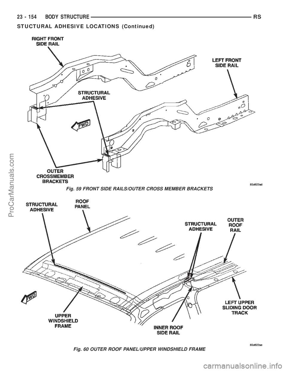
Fig. 59 FRONT SIDE RAILS/OUTER CROSS MEMBER BRACKETS
Fig. 60 OUTER ROOF PANEL/UPPER WINDSHIELD FRAME
23 - 154 BODY STRUCTURERS
STUCTURAL ADHESIVE LOCATIONS (Continued)
ProCarManuals.com
Page 2140 of 2399
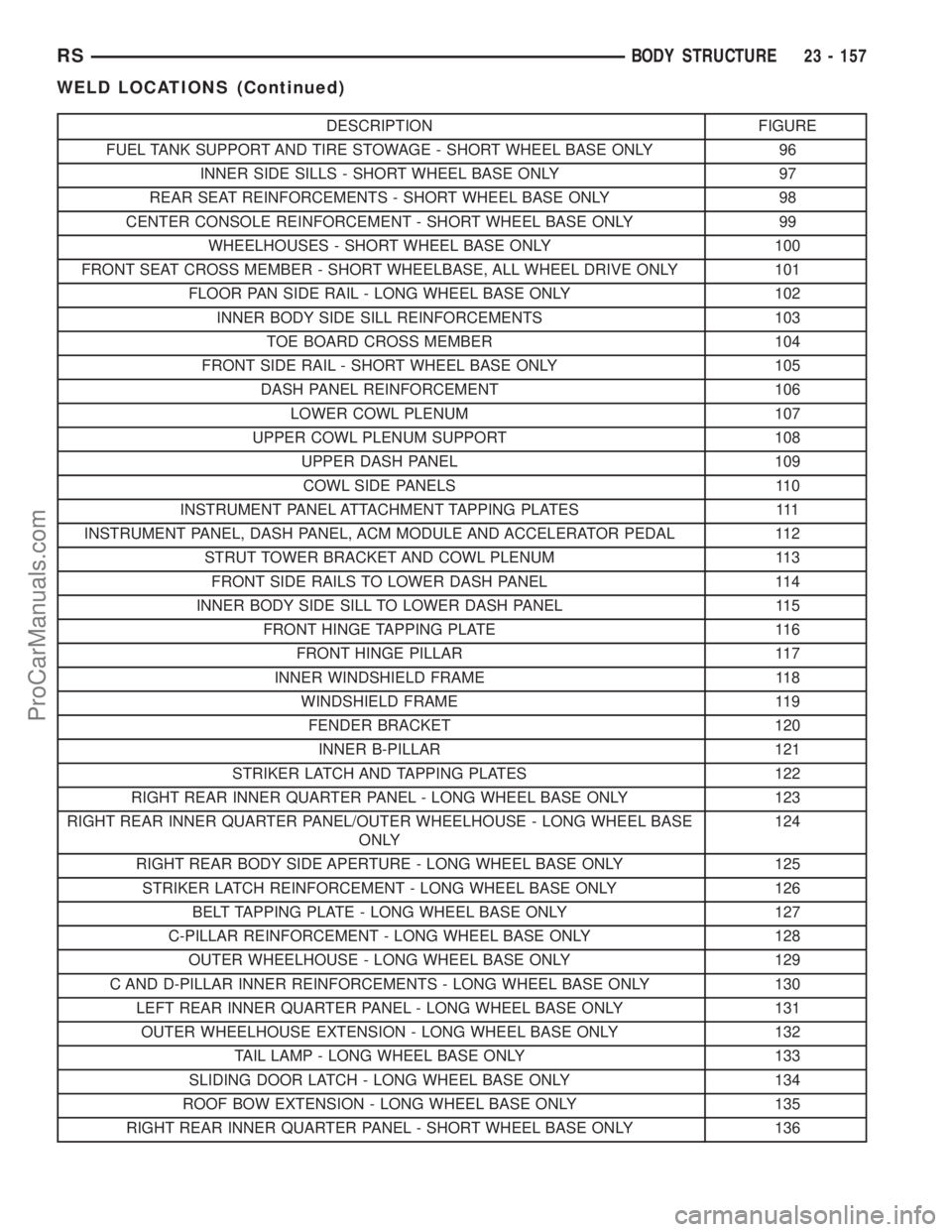
DESCRIPTION FIGURE
FUEL TANK SUPPORT AND TIRE STOWAGE - SHORT WHEEL BASE ONLY 96
INNER SIDE SILLS - SHORT WHEEL BASE ONLY 97
REAR SEAT REINFORCEMENTS - SHORT WHEEL BASE ONLY 98
CENTER CONSOLE REINFORCEMENT - SHORT WHEEL BASE ONLY 99
WHEELHOUSES - SHORT WHEEL BASE ONLY 100
FRONT SEAT CROSS MEMBER - SHORT WHEELBASE, ALL WHEEL DRIVE ONLY 101
FLOOR PAN SIDE RAIL - LONG WHEEL BASE ONLY 102
INNER BODY SIDE SILL REINFORCEMENTS 103
TOE BOARD CROSS MEMBER 104
FRONT SIDE RAIL - SHORT WHEEL BASE ONLY 105
DASH PANEL REINFORCEMENT 106
LOWER COWL PLENUM 107
UPPER COWL PLENUM SUPPORT 108
UPPER DASH PANEL 109
COWL SIDE PANELS 110
INSTRUMENT PANEL ATTACHMENT TAPPING PLATES 111
INSTRUMENT PANEL, DASH PANEL, ACM MODULE AND ACCELERATOR PEDAL 112
STRUT TOWER BRACKET AND COWL PLENUM 113
FRONT SIDE RAILS TO LOWER DASH PANEL 114
INNER BODY SIDE SILL TO LOWER DASH PANEL 115
FRONT HINGE TAPPING PLATE 116
FRONT HINGE PILLAR 117
INNER WINDSHIELD FRAME 118
WINDSHIELD FRAME 119
FENDER BRACKET 120
INNER B-PILLAR 121
STRIKER LATCH AND TAPPING PLATES 122
RIGHT REAR INNER QUARTER PANEL - LONG WHEEL BASE ONLY 123
RIGHT REAR INNER QUARTER PANEL/OUTER WHEELHOUSE - LONG WHEEL BASE
ONLY124
RIGHT REAR BODY SIDE APERTURE - LONG WHEEL BASE ONLY 125
STRIKER LATCH REINFORCEMENT - LONG WHEEL BASE ONLY 126
BELT TAPPING PLATE - LONG WHEEL BASE ONLY 127
C-PILLAR REINFORCEMENT - LONG WHEEL BASE ONLY 128
OUTER WHEELHOUSE - LONG WHEEL BASE ONLY 129
C AND D-PILLAR INNER REINFORCEMENTS - LONG WHEEL BASE ONLY 130
LEFT REAR INNER QUARTER PANEL - LONG WHEEL BASE ONLY 131
OUTER WHEELHOUSE EXTENSION - LONG WHEEL BASE ONLY 132
TAIL LAMP - LONG WHEEL BASE ONLY 133
SLIDING DOOR LATCH - LONG WHEEL BASE ONLY 134
ROOF BOW EXTENSION - LONG WHEEL BASE ONLY 135
RIGHT REAR INNER QUARTER PANEL - SHORT WHEEL BASE ONLY 136
RSBODY STRUCTURE23 - 157
WELD LOCATIONS (Continued)
ProCarManuals.com
Page 2141 of 2399
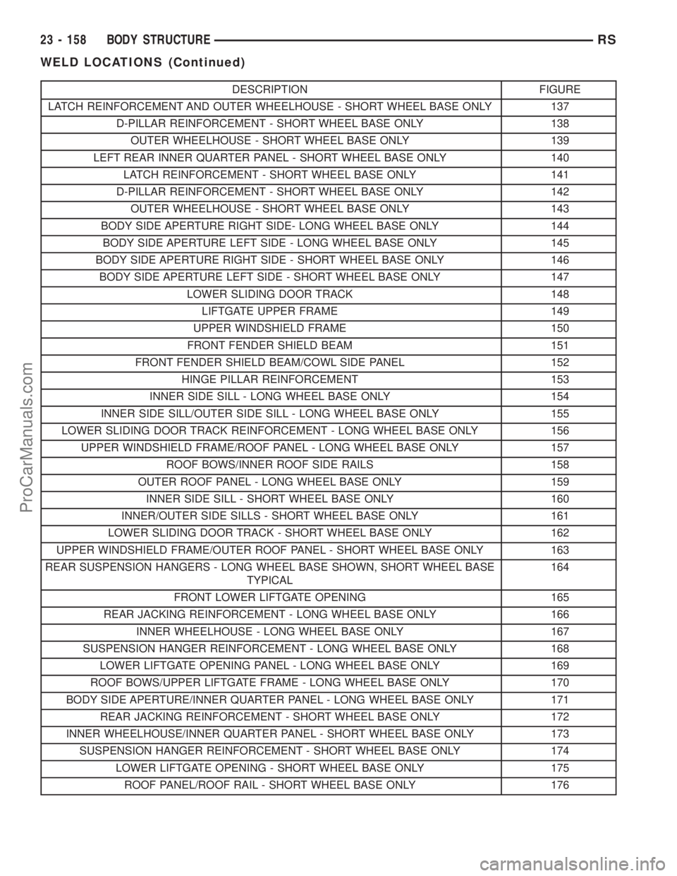
DESCRIPTION FIGURE
LATCH REINFORCEMENT AND OUTER WHEELHOUSE - SHORT WHEEL BASE ONLY 137
D-PILLAR REINFORCEMENT - SHORT WHEEL BASE ONLY 138
OUTER WHEELHOUSE - SHORT WHEEL BASE ONLY 139
LEFT REAR INNER QUARTER PANEL - SHORT WHEEL BASE ONLY 140
LATCH REINFORCEMENT - SHORT WHEEL BASE ONLY 141
D-PILLAR REINFORCEMENT - SHORT WHEEL BASE ONLY 142
OUTER WHEELHOUSE - SHORT WHEEL BASE ONLY 143
BODY SIDE APERTURE RIGHT SIDE- LONG WHEEL BASE ONLY 144
BODY SIDE APERTURE LEFT SIDE - LONG WHEEL BASE ONLY 145
BODY SIDE APERTURE RIGHT SIDE - SHORT WHEEL BASE ONLY 146
BODY SIDE APERTURE LEFT SIDE - SHORT WHEEL BASE ONLY 147
LOWER SLIDING DOOR TRACK 148
LIFTGATE UPPER FRAME 149
UPPER WINDSHIELD FRAME 150
FRONT FENDER SHIELD BEAM 151
FRONT FENDER SHIELD BEAM/COWL SIDE PANEL 152
HINGE PILLAR REINFORCEMENT 153
INNER SIDE SILL - LONG WHEEL BASE ONLY 154
INNER SIDE SILL/OUTER SIDE SILL - LONG WHEEL BASE ONLY 155
LOWER SLIDING DOOR TRACK REINFORCEMENT - LONG WHEEL BASE ONLY 156
UPPER WINDSHIELD FRAME/ROOF PANEL - LONG WHEEL BASE ONLY 157
ROOF BOWS/INNER ROOF SIDE RAILS 158
OUTER ROOF PANEL - LONG WHEEL BASE ONLY 159
INNER SIDE SILL - SHORT WHEEL BASE ONLY 160
INNER/OUTER SIDE SILLS - SHORT WHEEL BASE ONLY 161
LOWER SLIDING DOOR TRACK - SHORT WHEEL BASE ONLY 162
UPPER WINDSHIELD FRAME/OUTER ROOF PANEL - SHORT WHEEL BASE ONLY 163
REAR SUSPENSION HANGERS - LONG WHEEL BASE SHOWN, SHORT WHEEL BASE
TYPICAL164
FRONT LOWER LIFTGATE OPENING 165
REAR JACKING REINFORCEMENT - LONG WHEEL BASE ONLY 166
INNER WHEELHOUSE - LONG WHEEL BASE ONLY 167
SUSPENSION HANGER REINFORCEMENT - LONG WHEEL BASE ONLY 168
LOWER LIFTGATE OPENING PANEL - LONG WHEEL BASE ONLY 169
ROOF BOWS/UPPER LIFTGATE FRAME - LONG WHEEL BASE ONLY 170
BODY SIDE APERTURE/INNER QUARTER PANEL - LONG WHEEL BASE ONLY 171
REAR JACKING REINFORCEMENT - SHORT WHEEL BASE ONLY 172
INNER WHEELHOUSE/INNER QUARTER PANEL - SHORT WHEEL BASE ONLY 173
SUSPENSION HANGER REINFORCEMENT - SHORT WHEEL BASE ONLY 174
LOWER LIFTGATE OPENING - SHORT WHEEL BASE ONLY 175
ROOF PANEL/ROOF RAIL - SHORT WHEEL BASE ONLY 176
23 - 158 BODY STRUCTURERS
WELD LOCATIONS (Continued)
ProCarManuals.com
Page 2299 of 2399
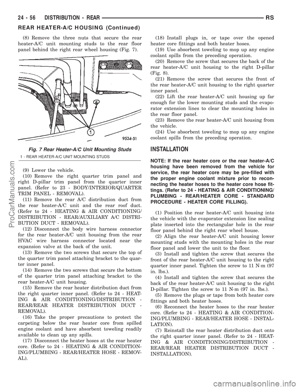
(8) Remove the three nuts that secure the rear
heater-A/C unit mounting studs to the rear floor
panel behind the right rear wheel housing (Fig. 7).
(9) Lower the vehicle.
(10) Remove the right quarter trim panel and
right D-pillar trim panel from the quarter inner
panel. (Refer to 23 - BODY/INTERIOR/QUARTER
TRIM PANEL - REMOVAL).
(11) Remove the rear A/C distribution duct from
the rear heater-A/C unit and the rear roof duct.
(Refer to 24 - HEATING & AIR CONDITIONING/
DISTRIBUTION - REAR/AUXILIARY A/C DISTRI-
BUTION DUCT - REMOVAL).
(12) Disconnect the body wire harness connector
for the rear heater-A/C unit housing from the rear
HVAC wire harness connector located near the
expansion valve at the back of the unit.
(13) Remove the two screws that secure the top of
the quarter trim panel attaching bracket to the quar-
ter inner panel.
(14) Remove the two screws that secure the bottom
of the quarter trim panel attaching bracket to the
rear heater-A/C unit housing.
(15) Remove the rear heater distribution duct from
the right quarter inner panel. (Refer to 24 - HEAT-
ING & AIR CONDITIONING/DISTRIBUTION -
REAR/REAR HEATER DISTRIBUTION DUCT -
REMOVAL).
(16) Take the proper precautions to protect the
carpeting below the rear heater core from spilled
engine coolant and have absorbent toweling readily
available to clean up any spills.
(17) Disconnect the heater hoses at the rear heater
core. (Refer to 24 - HEATING & AIR CONDITION-
ING/PLUMBING - REAR/HEATER HOSE - REMOV-
AL).(18) Install plugs in, or tape over the opened
heater core fittings and both heater hoses.
(19) Use absorbent toweling to mop up any engine
coolant spills from the preceding operation.
(20) Remove the screw that secures the back of the
rear heater-A/C unit housing to the right D-pillar
(Fig. 8).
(21) Remove the screw that secures the front of
the rear heater-A/C unit housing to the right quarter
inner panel.
(22) Lift the rear heater-A/C unit housing up far
enough for the lower mounting studs and the evapo-
rator extension lines to clear the mounting holes in
the rear floor panel.
(23) Remove the rear heater-A/C unit housing from
the vehicle.
(24) Use absorbent toweling to mop up any engine
coolant spills from the preceding operation.
INSTALLATION
NOTE: If the rear heater core or the rear heater-A/C
housing have been removed from the vehicle for
service, the rear heater core may be pre-filled with
the proper engine coolant mixture prior to recon-
necting the heater hoses to the heater core hose fit-
tings. (Refer to 24 - HEATING & AIR CONDITIONING/
PLUMBING - REAR/HEATER CORE - STANDARD
PROCEDURE - HEATER CORE FILLING).
(1) Position the rear heater-A/C unit housing into
the vehicle with the evaporator extension line sealing
plate inserted into the rectangular hole in the rear
floor panel behind the right rear wheel house.
(2) Align the rear heater-A/C unit housing lower
mounting studs with the mounting holes in the rear
floor panel and lower the unit to the floor.
(3) Install and tighten the screw that secures the
front of the rear heater-A/C unit housing to the right
quarter inner panel. Tighten the screw to 11 N´m (97
in. lbs.).
(4) Install and tighten the screw that secures the
back of the rear heater-A/C unit housing to the right
D-pillar. Tighten the screw to 11 N´m (97 in. lbs.).
(5) Remove the plugs or tape from both heater core
fittings and both heater hoses.
(6) Reconnect the heater hoses to the rear heater
core. (Refer to 24 - HEATING & AIR CONDITION-
ING/PLUMBING - REAR/HEATER HOSE - INSTAL-
LATION).
(7) Reinstall the rear heater distribution duct onto
the right quarter inner panel. (Refer to 24 - HEAT-
ING & AIR CONDITIONING/DISTRIBUTION -
REAR/REAR HEATER DISTRIBUTION DUCT -
INSTALLATION).
Fig. 7 Rear Heater-A/C Unit Mounting Studs
1 - REAR HEATER-A/C UNIT MOUNTING STUDS
24 - 56 DISTRIBUTION - REARRS
REAR HEATER-A/C HOUSING (Continued)
ProCarManuals.com
Page 2300 of 2399
(8) Install and tighten the two screws that secure
the bottom of the quarter trim panel attaching
bracket to the rear heater-A/C unit housing. Tighten
the screws to 1.7 N´m (15 in. lbs.).
(9) Install and tighten the two screws that secure
the top of the quarter trim panel attaching bracket to
the quarter inner panel.
(10) Reconnect the body wire harness connector for
the rear heater-A/C unit housing to the rear HVAC
wire harness connector located near the expansion
valve at the back of the unit.
(11) Reinstall the auxiliary A/C distribution duct
onto the rear heater-A/C unit and the rear roof duct.
(Refer to 24 - HEATING & AIR CONDITIONING/
DISTRIBUTION - REAR/AUXILIARY A/C DISTRI-
BUTION DUCT - INSTALLATION).
(12) Reinstall the right quarter trim panel and
right D-pillar trim panel onto the quarter inner
panel. (Refer to 23 - BODY/INTERIOR/QUARTER
TRIM PANEL - INSTALLATION).
(13) Raise and support the vehicle.(14) Install and tighten the three nuts that secure
the rear heater-A/C unit mounting studs to the rear
floor panel behind the right rear wheel housing.
Tighten the nuts to 9 N´m (80 in. lbs.).
(15) Remove the tape or plugs from the underbody
liquid line and suction line fittings and both ports in
the rear heater-A/C unit evaporator extension line
sealing plate that extends through the rear floor
panel behind the right rear wheel housing.
(16) Lubricate new rubber O-ring seals with clean
refrigerant oil and install them on the liquid line and
suction line fittings.
(17) Reconnect the underbody refrigerant line seal-
ing plate to the evaporator extension line sealing
plate.
(18) Install and tighten the screw that secures the
underbody refrigerant line sealing plate to the evap-
orator extension line sealing plate. Tighten the screw
to 23 N´m (17 ft. lbs.).
(19) Lower the vehicle.
(20) Reconnect the battery negative cable.
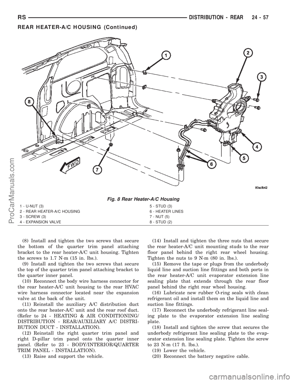
Fig. 8 Rear Heater-A/C Housing
1 - U-NUT (3)
2 - REAR HEATER-A/C HOUSING
3 - SCREW (3)
4 - EXPANSION VALVE5 - STUD (3)
6 - HEATER LINES
7 - NUT (5)
8 - STUD (2)
RSDISTRIBUTION - REAR24-57
REAR HEATER-A/C HOUSING (Continued)
ProCarManuals.com