2002 CHRYSLER VOYAGER speed sensor
[x] Cancel search: speed sensorPage 1838 of 2399
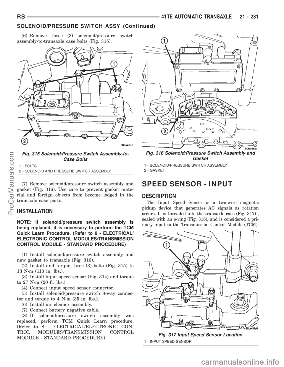
(6) Remove three (3) solenoid/pressure switch
assembly-to-transaxle case bolts (Fig. 315).
(7) Remove solenoid/pressure switch assembly and
gasket (Fig. 316). Use care to prevent gasket mate-
rial and foreign objects from become lodged in the
transaxle case ports.
INSTALLATION
NOTE: If solenoid/pressure switch assembly is
being replaced, it is necessary to perform the TCM
Quick Learn Procedure. (Refer to 8 - ELECTRICAL/
ELECTRONIC CONTROL MODULES/TRANSMISSION
CONTROL MODULE - STANDARD PROCEDURE)
(1) Install solenoid/pressure switch assembly and
new gasket to transaxle (Fig. 316).
(2) Install and torque three (3) bolts (Fig. 315) to
13 N´m (110 in. lbs.).
(3) Install input speed sensor (Fig. 314) and torque
to 27 N´m (20 ft. lbs.).
(4) Connect input speed sensor connector.
(5) Install solenoid/pressure switch 8-way connec-
tor and torque to 4 N´m (35 in. lbs.).
(6) Install air cleaner assembly.
(7) Connect battery negative cable.
(8) If solenoid/pressure switch assembly was
replaced, perform TCM Quick Learn procedure.
(Refer to 8 - ELECTRICAL/ELECTRONIC CON-
TROL MODULES/TRANSMISSION CONTROL
MODULE - STANDARD PROCEDURE)
SPEED SENSOR - INPUT
DESCRIPTION
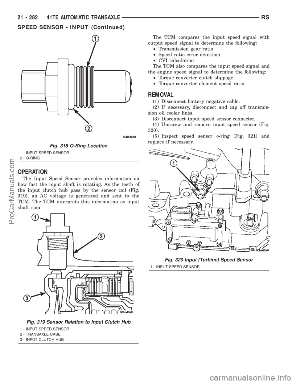
The Input Speed Sensor is a two-wire magnetic
pickup device that generates AC signals as rotation
occurs. It is threaded into the transaxle case (Fig. 317) ,
sealed with an o-ring (Fig. 318), and is considered a pri-
mary input to the Transmission Control Module (TCM).
Fig. 315 Solenoid/Pressure Switch Assembly-to-
Case Bolts
1 - BOLTS
2 - SOLENOID AND PRESSURE SWITCH ASSEMBLY
Fig. 316 Solenoid/Pressure Switch Assembly and
Gasket
1 - SOLENOID/PRESSURE SWITCH ASSEMBLY
2 - GASKET
Fig. 317 Input Speed Sensor Location
1 - INPUT SPEED SENSOR
RS41TE AUTOMATIC TRANSAXLE21 - 281
SOLENOID/PRESSURE SWITCH ASSY (Continued)
ProCarManuals.com
Page 1839 of 2399
OPERATION
The Input Speed Sensor provides information on
how fast the input shaft is rotating. As the teeth of
the input clutch hub pass by the sensor coil (Fig.
319), an AC voltage is generated and sent to the
TCM. The TCM interprets this information as input
shaft rpm.The TCM compares the input speed signal with
output speed signal to determine the following:
²Transmission gear ratio
²Speed ratio error detection
²CVI calculation
The TCM also compares the input speed signal and
the engine speed signal to determine the following:
²Torque converter clutch slippage
²Torque converter element speed ratio
REMOVAL
(1) Disconnect battery negative cable.
(2) If necessary, disconnect and cap off transmis-
sion oil cooler lines.
(3) Disconnect input speed sensor connector.
(4) Unscrew and remove input speed sensor (Fig.
320).
(5) Inspect speed sensor o-ring (Fig. 321) and
replace if necessary.
Fig. 318 O-Ring Location
1 - INPUT SPEED SENSOR
2 - O-RING
Fig. 319 Sensor Relation to Input Clutch Hub
1 - INPUT SPEED SENSOR
2 - TRANSAXLE CASE
3 - INPUT CLUTCH HUB
Fig. 320 Input (Turbine) Speed Sensor
1 - INPUT SPEED SENSOR
21 - 282 41TE AUTOMATIC TRANSAXLERS
SPEED SENSOR - INPUT (Continued)
ProCarManuals.com
Page 1840 of 2399
INSTALLATION
(1) Verify o-ring is installed into position.
(2) Install and tighten input speed sensor to 27
N´m (20 ft. lbs.).
(3) Connect speed sensor connector.
(4) Connect battery negative cable.
SPEED SENSOR - OUTPUT
DESCRIPTION
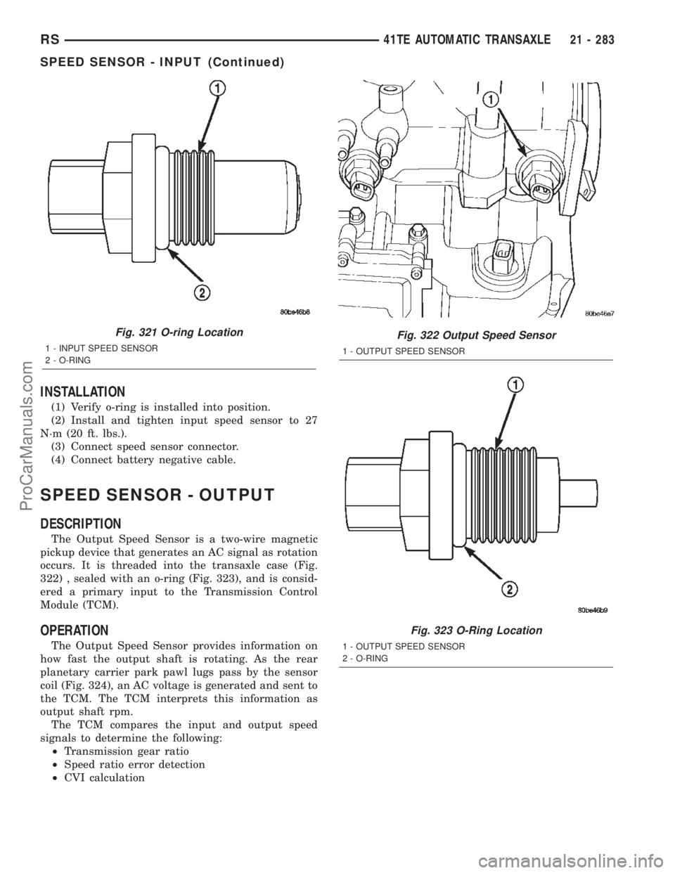
The Output Speed Sensor is a two-wire magnetic
pickup device that generates an AC signal as rotation
occurs. It is threaded into the transaxle case (Fig.
322) , sealed with an o-ring (Fig. 323), and is consid-
ered a primary input to the Transmission Control
Module (TCM).
OPERATION
The Output Speed Sensor provides information on
how fast the output shaft is rotating. As the rear
planetary carrier park pawl lugs pass by the sensor
coil (Fig. 324), an AC voltage is generated and sent to
the TCM. The TCM interprets this information as
output shaft rpm.
The TCM compares the input and output speed
signals to determine the following:
²Transmission gear ratio
²Speed ratio error detection
²CVI calculation
Fig. 321 O-ring Location
1 - INPUT SPEED SENSOR
2 - O-RING
Fig. 322 Output Speed Sensor
1 - OUTPUT SPEED SENSOR
Fig. 323 O-Ring Location
1 - OUTPUT SPEED SENSOR
2 - O-RING
RS41TE AUTOMATIC TRANSAXLE21 - 283
SPEED SENSOR - INPUT (Continued)
ProCarManuals.com
Page 1841 of 2399

VEHICLE SPEED SIGNAL
The vehicle speed signal is taken from the Output
Speed Sensor. The TCM converts this signal into a
pulse per mile signal and sends it to the PCM. The
PCM, in turn, sends the vehicle speed message
across the communication bus to the BCM. The BCM
sends this signal to the Instrument Cluster to dis-
play vehicle speed to the driver. The vehicle speed
signal pulse is roughly 8000 pulses per mile.
REMOVAL
(1) Disconnect battery negative cable.
(2) Raise vehicle on hoist.
(3) Disconnect output speed sensor connector.
(4) Unscrew and remove output speed sensor (Fig.
325).
(5) Inspect speed sensor o-ring (Fig. 326) and
replace if necessary.
INSTALLATION
(1) Verify o-ring is installed into position (Fig.
326).
(2) Install and tighten input speed sensor to 27
N´m (20 ft. lbs.).
(3) Connect speed sensor connector.
(4) Connect battery negative cable.
Fig. 324 Sensor Relation to Planet Carrier Park Pawl
1 - OUTPUT SPEED SENSOR
2 - REAR PLANET CARRIER/OUTPUT SHAFT ASSEMBLY
3 - TRANSAXLE CASE
Fig. 325 Output Speed Sensor
1 - OUTPUT SPEED SENSOR
Fig. 326 O-ring Location
1 - OUTPUT SPEED SENSOR
2 - O-RING
21 - 284 41TE AUTOMATIC TRANSAXLERS
SPEED SENSOR - OUTPUT (Continued)
ProCarManuals.com
Page 1865 of 2399
T850 MANUAL TRANSAXLE
TABLE OF CONTENTS
page page
T850 MANUAL TRANSAXLE
DESCRIPTION........................308
OPERATION..........................311
DIAGNOSIS AND TESTING - COMMON
PROBLEM CAUSES...................318
REMOVAL............................318
DISASSEMBLY........................323
ASSEMBLY...........................329
INSTALLATION........................338
SPECIFICATIONS - T850 MANUAL
TRANSAXLE........................343
SPECIAL TOOLS - T850 TRANSAXLE.......345
AXLE SEALS
REMOVAL............................348
INSTALLATION........................348
BACK-UP LAMP SWITCH
REMOVAL............................349
INSTALLATION........................349
DIFFERENTIAL
DESCRIPTION........................349
OPERATION..........................349
DISASSEMBLY........................350
ASSEMBLY...........................353
ADJUSTMENTS
ADJUSTMENT - DIFFERENTIAL TURNING
TORQUE...........................356
ADJUSTMENT - DIFFERENTIAL SIDE GEAR
ENDPLAY..........................358
FLUID
STANDARD PROCEDURE
STANDARD PROCEDURE - FLUID LEVEL
CHECK............................358
STANDARD PROCEDURE - FLUID DRAIN
AND FILL...........................359
GEARSHIFT BOOT
REMOVAL............................359
INSTALLATION........................360GEARSHIFT CABLE - CROSSOVER
REMOVAL............................360
INSTALLATION........................363
ADJUSTMENTS
ADJUSTMENT.......................366
GEARSHIFT CABLE - SELECTOR
REMOVAL............................368
INSTALLATION........................371
GEARSHIFT KNOB
REMOVAL............................374
INSTALLATION........................374
GEARSHIFT MECHANISM
REMOVAL............................375
INSTALLATION........................377
INPUT SHAFT
DESCRIPTION........................380
DISASSEMBLY........................380
ASSEMBLY...........................383
INTERMEDIATE SHAFT
DESCRIPTION........................387
DISASSEMBLY........................388
ASSEMBLY...........................395
SHIFT COVER
DESCRIPTION........................401
SHIFT FORK AND SHAFT
DESCRIPTION........................402
SYNCHRONIZER
DESCRIPTION........................402
DISASSEMBLY........................402
CLEANING
CLEAN............................402
INSPECTION
INSPECT...........................402
ASSEMBLY...........................403
VEHICLE SPEED SENSOR
REMOVAL............................403
INSTALLATION........................403
T850 MANUAL TRANSAXLE
DESCRIPTION
The NV T850 5-speed transaxle (Fig. 1) is a con-
stant-mesh manual transaxle that is synchronized in
all gear ranges, including reverse.
The transaxle consists of three major sub-assem-
blies: the input shaft, intermediate shaft, and differ-ential assembly. The transaxle shift system consists
of a mechanical shift cover, rails, forks, and cables.
The unique design of this shift system provides a
higher mechanical advantage, resulting in less fric-
tion and lower shift cable loads for smoother, more
positive operation.
21 - 308 T850 MANUAL TRANSAXLERS
ProCarManuals.com
Page 1960 of 2399
If any of these conditions exist in these compo-
nents, replace as necessary.
ASSEMBLY
(1) Position synchronizer hub onto work bench.
Hub is non-directional.
(2) Install springs into hub slot.
(3) Insert key into hub and spring.
(4) Apply petroleum jelly to the hole in the key.
Insert balls into each key.
(5) Slide sleeve over the hub and depress balls as
you carefully slip the sleeve into position.
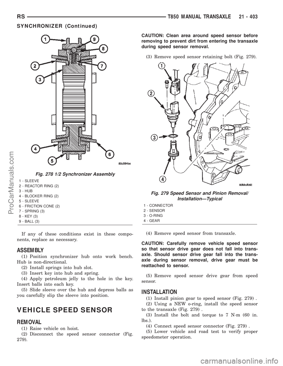
VEHICLE SPEED SENSOR
REMOVAL
(1) Raise vehicle on hoist.
(2) Disconnect the speed sensor connector (Fig.
279).CAUTION: Clean area around speed sensor before
removing to prevent dirt from entering the transaxle
during speed sensor removal.
(3) Remove speed sensor retaining bolt (Fig. 279).
(4) Remove speed sensor from transaxle.
CAUTION: Carefully remove vehicle speed sensor
so that sensor drive gear does not fall into trans-
axle. Should sensor drive gear fall into the trans-
axle during sensor removal, drive gear must be
reattached to sensor.
(5) Remove speed sensor drive gear from speed
sensor.
INSTALLATION
(1) Install pinion gear to speed sensor (Fig. 279) .
(2) Using a NEW o-ring, install the speed sensor
to the transaxle (Fig. 279) .
(3) Install the bolt and torque to 7 N´m (60 in.
lbs.).
(4) Connect speed sensor connector (Fig. 279) .
(5) Lower vehicle and road test to verify proper
speedometer operation.
Fig. 278 1/2 Synchronizer Assembly
1 - SLEEVE
2 - REACTOR RING (2)
3 - HUB
4 - BLOCKER RING (2)
5 - SLEEVE
6 - FRICTION CONE (2)
7 - SPRING (3)
8 - KEY (3)
9 - BALL (3)
Fig. 279 Speed Sensor and Pinion Removal/
InstallationÐTypical
1 - CONNECTOR
2 - SENSOR
3 - O-RING
4 - GEAR
RST850 MANUAL TRANSAXLE21 - 403
SYNCHRONIZER (Continued)
ProCarManuals.com
Page 1962 of 2399
TIRES/WHEELS
TABLE OF CONTENTS
page page
TIRES/WHEELS
DIAGNOSIS AND TESTING - TIRE AND
WHEEL VIBRATION.....................1
STANDARD PROCEDURE
STANDARD PROCEDURE - TIRE AND
WHEEL BALANCE......................5
STANDARD PROCEDURE - TIRE AND
WHEEL MATCH MOUNTING..............5
STANDARD PROCEDURE - TIRE AND
WHEEL ROTATION.....................7
REMOVAL
REMOVAL - TIRE AND WHEEL ASSEMBLY
(ALUMINUM WHEEL)....................7
REMOVAL - TIRE AND WHEEL ASSEMBLY
(STEEL WHEEL).......................7
INSTALLATION
INSTALLATION - TIRE AND WHEEL
ASSEMBLY (ALUMINUM WHEEL)..........8
INSTALLATION - TIRE AND WHEEL
ASSEMBLY (STEEL WHEEL)..............8
TIRE PRESSURE MONITORING (TPM)
DESCRIPTION..........................9
OPERATION............................9
SENSOR - TPM
DESCRIPTION.........................10
OPERATION...........................10
CAUTION.............................10
DIAGNOSIS AND TESTING - TIRE PRESSURE
SENSOR............................10
STANDARD PROCEDURE - TIRE PRESSURE
SENSOR RETRAIN....................10
REMOVAL.............................11
INSTALLATION.........................11
TIRES
DESCRIPTION
DESCRIPTION - TIRE..................13
DESCRIPTION - RADIAL-PLY TIRES.......13DESCRIPTION - REPLACEMENT TIRES....14
DESCRIPTION - SPARE TIRE
(TEMPORARY).......................14
DIAGNOSIS AND TESTING
DIAGNOSIS AND TESTING - TIRE NOISE . . . 14
DIAGNOSIS AND TESTING - TIRE/VEHICLE
LEAD...............................14
DIAGNOSIS AND TESTING - TIRE WEAR
PATTERNS..........................14
DIAGNOSIS AND TESTING - TREAD WEAR
INDICATORS.........................14
STANDARD PROCEDURE
STANDARD PROCEDURE - TIRE INFLATION
PRESSURES.........................14
STANDARD PROCEDURE - TIRE
PRESSURE FOR HIGH SPEED
OPERATION.........................17
STANDARD PROCEDURE - TIRE LEAK
REPAIRING..........................17
CLEANING - TIRES.....................17
WHEELS
DESCRIPTION - WHEEL..................17
DIAGNOSIS AND TESTING - WHEEL
INSPECTION.........................18
CLEANING - ALUMINUM WHEEL CARE......18
SPECIFICATIONS
WHEEL.............................19
WHEEL COVER
DESCRIPTION.........................19
REMOVAL.............................19
INSTALLATION.........................19
WHEEL MOUNTING STUDS - FRONT
REMOVAL.............................20
INSTALLATION.........................21
WHEEL MOUNTING STUDS - REAR
REMOVAL.............................21
INSTALLATION.........................22
TIRES/WHEELS
DIAGNOSIS AND TESTING - TIRE AND WHEEL
VIBRATION
Tire and wheel imbalance, runout and force varia-
tion can cause vehicles to exhibit steering wheel
vibration.
VISUAL INSPECTION
Visual inspection of the vehicle is recommended
prior to road testing or performing any other proce-
dure. Raise vehicle on a suitable hoist. (Refer to
LUBRICATION & MAINTENANCE/HOISTING -
STANDARD PROCEDURE)
RSTIRES/WHEELS22-1
ProCarManuals.com
Page 1970 of 2399
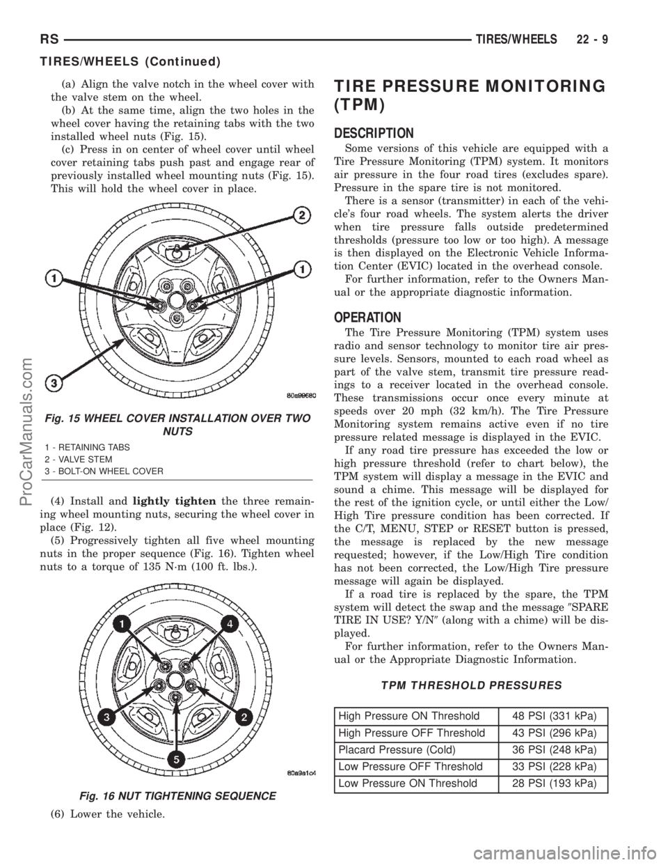
(a) Align the valve notch in the wheel cover with
the valve stem on the wheel.
(b) At the same time, align the two holes in the
wheel cover having the retaining tabs with the two
installed wheel nuts (Fig. 15).
(c) Press in on center of wheel cover until wheel
cover retaining tabs push past and engage rear of
previously installed wheel mounting nuts (Fig. 15).
This will hold the wheel cover in place.
(4) Install andlightly tightenthe three remain-
ing wheel mounting nuts, securing the wheel cover in
place (Fig. 12).
(5) Progressively tighten all five wheel mounting
nuts in the proper sequence (Fig. 16). Tighten wheel
nuts to a torque of 135 N´m (100 ft. lbs.).
(6) Lower the vehicle.TIRE PRESSURE MONITORING
(TPM)
DESCRIPTION
Some versions of this vehicle are equipped with a
Tire Pressure Monitoring (TPM) system. It monitors
air pressure in the four road tires (excludes spare).
Pressure in the spare tire is not monitored.
There is a sensor (transmitter) in each of the vehi-
cle's four road wheels. The system alerts the driver
when tire pressure falls outside predetermined
thresholds (pressure too low or too high). A message
is then displayed on the Electronic Vehicle Informa-
tion Center (EVIC) located in the overhead console.
For further information, refer to the Owners Man-
ual or the appropriate diagnostic information.
OPERATION
The Tire Pressure Monitoring (TPM) system uses
radio and sensor technology to monitor tire air pres-
sure levels. Sensors, mounted to each road wheel as
part of the valve stem, transmit tire pressure read-
ings to a receiver located in the overhead console.
These transmissions occur once every minute at
speeds over 20 mph (32 km/h). The Tire Pressure
Monitoring system remains active even if no tire
pressure related message is displayed in the EVIC.
If any road tire pressure has exceeded the low or
high pressure threshold (refer to chart below), the
TPM system will display a message in the EVIC and
sound a chime. This message will be displayed for
the rest of the ignition cycle, or until either the Low/
High Tire pressure condition has been corrected. If
the C/T, MENU, STEP or RESET button is pressed,
the message is replaced by the new message
requested; however, if the Low/High Tire condition
has not been corrected, the Low/High Tire pressure
message will again be displayed.
If a road tire is replaced by the spare, the TPM
system will detect the swap and the message9SPARE
TIRE IN USE? Y/N9(along with a chime) will be dis-
played.
For further information, refer to the Owners Man-
ual or the Appropriate Diagnostic Information.
TPM THRESHOLD PRESSURES
High Pressure ON Threshold 48 PSI (331 kPa)
High Pressure OFF Threshold 43 PSI (296 kPa)
Placard Pressure (Cold) 36 PSI (248 kPa)
Low Pressure OFF Threshold 33 PSI (228 kPa)
Low Pressure ON Threshold 28 PSI (193 kPa)
Fig. 15 WHEEL COVER INSTALLATION OVER TWO
NUTS
1 - RETAINING TABS
2 - VALVE STEM
3 - BOLT-ON WHEEL COVER
Fig. 16 NUT TIGHTENING SEQUENCE
RSTIRES/WHEELS22-9
TIRES/WHEELS (Continued)
ProCarManuals.com