2002 CHRYSLER VOYAGER check oil
[x] Cancel search: check oilPage 1341 of 2399
OIL COOLER & LINES
DESCRIPTION
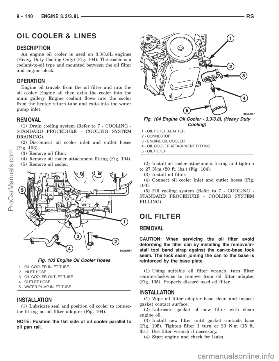
An engine oil cooler is used on 3.3/3.8L engines
(Heavy Duty Cooling Only) (Fig. 104). The cooler is a
coolant-to-oil type and mounted between the oil filter
and engine block.
OPERATION
Engine oil travels from the oil filter and into the
oil cooler. Engine oil then exits the cooler into the
main gallery. Engine coolant flows into the cooler
from the heater return tube and exits into the water
pump inlet.
REMOVAL
(1) Drain cooling system (Refer to 7 - COOLING -
STANDARD PROCEDURE - COOLING SYSTEM
DRAINING).
(2) Disconnect oil cooler inlet and outlet hoses
(Fig. 103).
(3) Remove oil filter.
(4) Remove oil cooler attachment fitting (Fig. 104).
(5) Remove oil cooler.
INSTALLATION
(1) Lubricate seal and position oil cooler to connec-
tor fitting on oil filter adapter (Fig. 104).
NOTE: Position the flat side of oil cooler parallel to
oil pan rail.(2) Install oil cooler attachment fitting and tighten
to 27 N´m (20 ft. lbs.) (Fig. 104).
(3) Install oil filter.
(4) Connect oil cooler inlet and outlet hoses (Fig.
103).
(5) Fill cooling system (Refer to 7 - COOLING -
STANDARD PROCEDURE - COOLING SYSTEM
FILLING).
OIL FILTER
REMOVAL
CAUTION: When servicing the oil filter avoid
deforming the filter can by installing the remove/in-
stall tool band strap against the can-to-base lock
seam. The lock seam joining the can to the base is
reinforced by the base plate.
(1) Using suitable oil filter wrench, turn filter
counterclockwise to remove from oil filter adapter
(Fig. 105). Properly discard used oil filter.
INSTALLATION
(1) Wipe oil filter adapter base clean and inspect
gasket contact surface.
(2) Lubricate gasket of new filter with clean
engine oil.
(3) Install new filter until gasket contacts base
(Fig. 105). Tighten filter 1 turn or 20 N´m (15 ft.
lbs.). Use filter wrench if necessary.
(4) Start engine and check for leaks.
Fig. 103 Engine Oil Cooler Hoses
1 - OIL COOLER INLET TUBE
2 - INLET HOSE
3 - OIL COOLER OUTLET TUBE
4 - OUTLET HOSE
5 - WATER PUMP INLET TUBE
Fig. 104 Engine Oil Cooler - 3.3/3.8L (Heavy Duty
Cooling)
1 - OIL FILTER ADAPTER
2 - CONNECTOR
3 - ENGINE OIL COOLER
4 - OIL COOLER ATTACHMENT FITTING
5 - OIL FILTER
9 - 140 ENGINE 3.3/3.8LRS
ProCarManuals.com
Page 1342 of 2399
OIL FILTER ADAPTER
REMOVAL
(1) Raise vehicle on hoist.
(2) Remove the oil filter.
(3) Disconnect oil pressure switch electrical con-
nector.
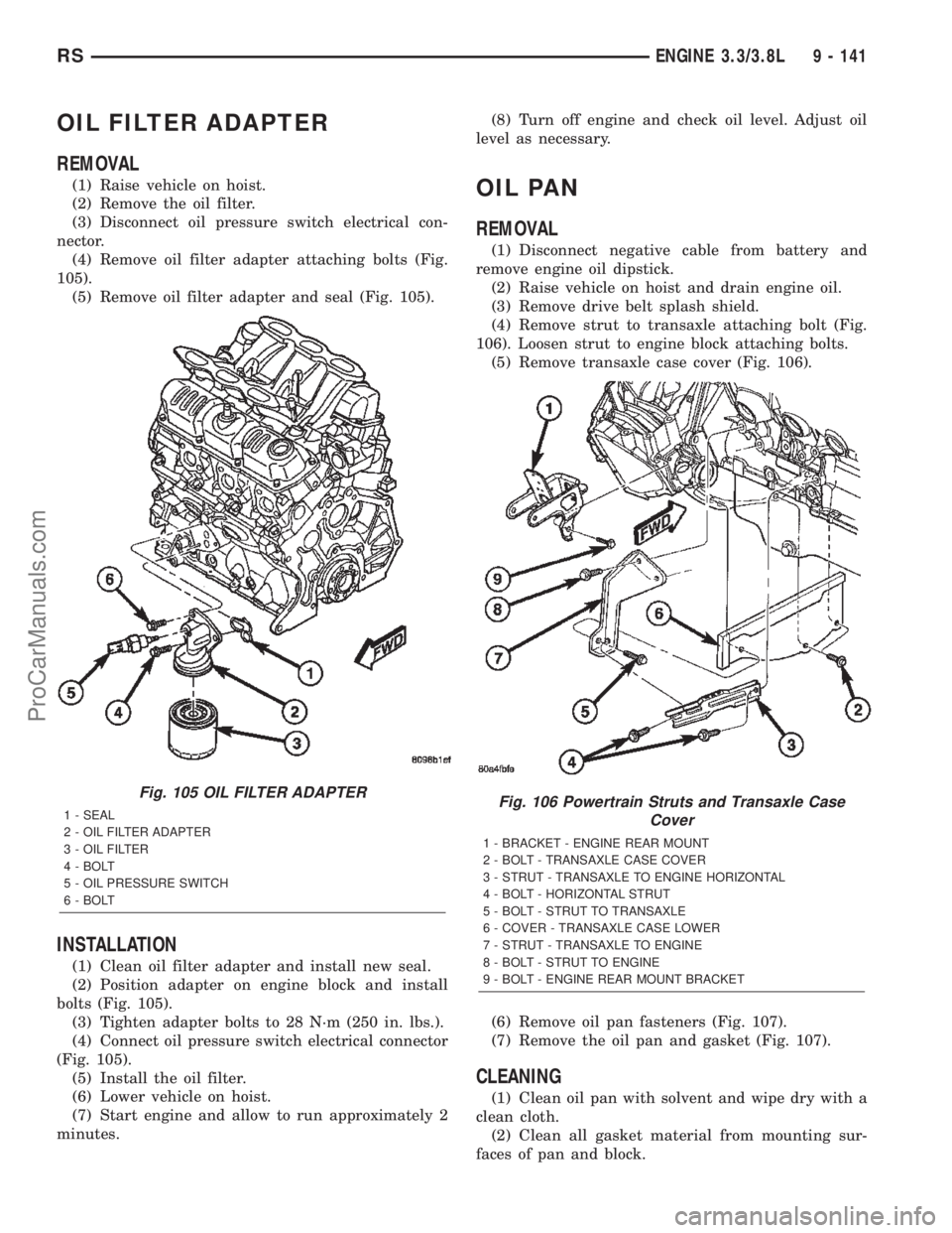
(4) Remove oil filter adapter attaching bolts (Fig.
105).
(5) Remove oil filter adapter and seal (Fig. 105).
INSTALLATION
(1) Clean oil filter adapter and install new seal.
(2) Position adapter on engine block and install
bolts (Fig. 105).
(3) Tighten adapter bolts to 28 N´m (250 in. lbs.).
(4) Connect oil pressure switch electrical connector
(Fig. 105).
(5) Install the oil filter.
(6) Lower vehicle on hoist.
(7) Start engine and allow to run approximately 2
minutes.(8) Turn off engine and check oil level. Adjust oil
level as necessary.
OIL PAN
REMOVAL
(1) Disconnect negative cable from battery and
remove engine oil dipstick.
(2) Raise vehicle on hoist and drain engine oil.
(3) Remove drive belt splash shield.
(4) Remove strut to transaxle attaching bolt (Fig.
106). Loosen strut to engine block attaching bolts.
(5) Remove transaxle case cover (Fig. 106).
(6) Remove oil pan fasteners (Fig. 107).
(7) Remove the oil pan and gasket (Fig. 107).
CLEANING
(1) Clean oil pan with solvent and wipe dry with a
clean cloth.
(2) Clean all gasket material from mounting sur-
faces of pan and block.
Fig. 105 OIL FILTER ADAPTER
1 - SEAL
2 - OIL FILTER ADAPTER
3 - OIL FILTER
4 - BOLT
5 - OIL PRESSURE SWITCH
6 - BOLTFig. 106 Powertrain Struts and Transaxle Case
Cover
1 - BRACKET - ENGINE REAR MOUNT
2 - BOLT - TRANSAXLE CASE COVER
3 - STRUT - TRANSAXLE TO ENGINE HORIZONTAL
4 - BOLT - HORIZONTAL STRUT
5 - BOLT - STRUT TO TRANSAXLE
6 - COVER - TRANSAXLE CASE LOWER
7 - STRUT - TRANSAXLE TO ENGINE
8 - BOLT - STRUT TO ENGINE
9 - BOLT - ENGINE REAR MOUNT BRACKET
RSENGINE 3.3/3.8L9 - 141
ProCarManuals.com
Page 1344 of 2399
INSTALLATION
(1) Clean relief valve, spring and bore.
NOTE: Lubricate relief valve with clean engine oil
before installing.
(2) Install relief valve and spring into housing.
(3) Install new retainer cap until flush with seal-
ing surface.
(4) Install oil pan (Refer to 9 - ENGINE/LUBRI-
CATION/OIL PAN - INSTALLATION).
(5) Fill crankcase with proper oil to correct level.
OIL PRESSURE SWITCH
DESCRIPTION
The engine oil pressure switch is located on the
lower left front side of the engine. It screws into the
oil filter adapter. The normally closed switch provides
an input through a single wire to the low pressure
indicator light on the instrument cluster.
OPERATION
The oil pressure switch provides a ground for the
instrument cluster low oil pressure indicator light.
The switch receives oil pressure input from the
engine main oil gallery. When engine oil pressure is
greater than 27.5 Kpa (4 psi), the switch contacts
open, providing a open circuit to the low pressure
indicator light. For wiring circuits and diagnostic
information, (Refer to Appropriate Wiring/Diagnostic
Information).
REMOVAL
(1) Raise vehicle on hoist.
(2) Disconnect electrical connector from switch.
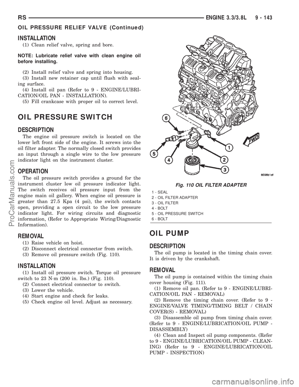
(3) Remove oil pressure switch (Fig. 110).
INSTALLATION
(1) Install oil pressure switch. Torque oil pressure
switch to 23 N´m (200 in. lbs.) (Fig. 110).
(2) Connect electrical connector to switch.
(3) Lower the vehicle.
(4) Start engine and check for leaks.
(5) Check engine oil level. Adjust as necessary.
OIL PUMP
DESCRIPTION
The oil pump is located in the timing chain cover.
It is driven by the crankshaft.
REMOVAL
The oil pump is contained within the timing chain
cover housing (Fig. 111).
(1) Remove oil pan. (Refer to 9 - ENGINE/LUBRI-
CATION/OIL PAN - REMOVAL)
(2) Remove the timing chain cover. (Refer to 9 -
ENGINE/VALVE TIMING/TIMING BELT / CHAIN
COVER(S) - REMOVAL)
(3) Disassemble oil pump from timing chain cover.
(Refer to 9 - ENGINE/LUBRICATION/OIL PUMP -
DISASSEMBLY)
(4) Clean and Inspect oil pump components. (Refer
to 9 - ENGINE/LUBRICATION/OIL PUMP - CLEAN-
ING) (Refer to 9 - ENGINE/LUBRICATION/OIL
PUMP - INSPECTION)
Fig. 110 OIL FILTER ADAPTER
1 - SEAL
2 - OIL FILTER ADAPTER
3 - OIL FILTER
4 - BOLT
5 - OIL PRESSURE SWITCH
6 - BOLT
RSENGINE 3.3/3.8L9 - 143
OIL PRESSURE RELIEF VALVE (Continued)
ProCarManuals.com
Page 1345 of 2399
DISASSEMBLY
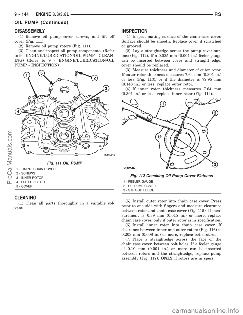
(1) Remove oil pump cover screws, and lift off
cover (Fig. 111).
(2) Remove oil pump rotors (Fig. 111).
(3) Clean and inspect oil pump components. (Refer
to 9 - ENGINE/LUBRICATION/OIL PUMP - CLEAN-
ING) (Refer to 9 - ENGINE/LUBRICATION/OIL
PUMP - INSPECTION)
CLEANING
(1) Clean all parts thoroughly in a suitable sol-
vent.
INSPECTION
(1) Inspect mating surface of the chain case cover.
Surface should be smooth. Replace cover if scratched
or grooved.
(2) Lay a straightedge across the pump cover sur-
face (Fig. 112). If a 0.025 mm (0.001 in.) feeler gauge
can be inserted between cover and straight edge,
cover should be replaced.
(3) Measure thickness and diameter of outer rotor.
If outer rotor thickness measures 7.64 mm (0.301 in.)
or less (Fig. 113), or if the diameter is 79.95 mm
(3.148 in.) or less, replace outer rotor.
(4) If inner rotor thickness measures 7.64 mm
(0.301 in.) or less, replace inner rotor (Fig. 114).
(5) Install outer rotor into chain case cover. Press
rotor to one side with fingers and measure clearance
between rotor and chain case cover (Fig. 115). If mea-
surement is 0.39 mm (0.015 in.) or more, replace
chain case cover, only if outer rotor is in specification.
(6) Install inner rotor into chain case cover. If
clearance between inner and outer rotors (Fig. 116) is
0.203 mm (0.008 in.) or more, replace both rotors.
(7) Place a straightedge across the face of the
chain case cover, between bolt holes. If a feeler gauge
of 0.10 mm (0.004 in.) or more can be inserted
between rotors and the straightedge, replace pump
assembly (Fig. 117).ONLYif rotors are in specs.
Fig. 111 OIL PUMP
1 - TIMING CHAIN COVER
2 - SCREWS
3 - INNER ROTOR
4 - OUTER ROTOR
5 - COVER
Fig. 112 Checking Oil Pump Cover Flatness
1 - FEELER GAUGE
2 - OIL PUMP COVER
3 - STRAIGHT EDGE
9 - 144 ENGINE 3.3/3.8LRS
OIL PUMP (Continued)
ProCarManuals.com
Page 1351 of 2399
(11) Install air cleaner and air inlet hose assembly.
(12) Connect the inlet air temperature (IAT) sen-
sor electrical connector.
(13) Connect battery negative cable.
INTAKE MANIFOLD - LOWER
REMOVAL - LOWER INTAKE MANIFOLD
(1) Perform fuel system pressure release procedure
(before attempting any repairs).(Refer to 14 -
FUEL SYSTEM/FUEL DELIVERY - STANDARD
PROCEDURE)
(2) Drain the cooling system. (Refer to 7 - COOL-
ING - STANDARD PROCEDURE)
(3) Remove the upper intake manifold. (Refer to 9
- ENGINE/MANIFOLDS/INTAKE MANIFOLD -
REMOVAL)
(4) Remove the fuel line. (Refer to 14 - FUEL SYS-
TEM/FUEL DELIVERY/FUEL LINES - STANDARD
PROCEDURE) (Refer to 14 - FUEL SYSTEM/FUEL
DELIVERY/QUICK CONNECT FITTING - STAN-
DARD PROCEDURE)
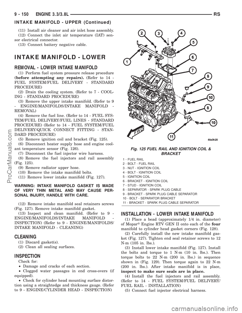
(5) Remove ignition coil and bracket (Fig. 125).
(6) Disconnect heater supply hose and engine cool-
ant temperature sensor (Fig. 126).
(7) Disconnect the fuel injector wire harness.
(8) Remove the fuel injectors and rail assembly
(Fig. 125).
(9) Remove radiator upper hose.
(10) Remove the intake manifold bolts.
(11) Remove lower intake manifold (Fig. 127).
WARNING: INTAKE MANIFOLD GASKET IS MADE
OF VERY THIN METAL AND MAY CAUSE PER-
SONAL INJURY, HANDLE WITH CARE.
(12) Remove intake manifold seal retainers screws
(Fig. 127). Remove intake manifold gasket.
(13) Inspect and clean manifold. (Refer to 9 -
ENGINE/MANIFOLDS/INTAKE MANIFOLD -
INSPECTION) (Refer to 9 - ENGINE/MANIFOLDS/
INTAKE MANIFOLD - CLEANING)
CLEANING
(1) Discard gasket(s).
(2) Clean all sealing surfaces.
INSPECTION
Check for:
²Damage and cracks of each section.
²Clogged water passages in end cross-overs (if
equipped).
²Check for cylinder head mounting surface distor-
tion using a straightedge and thickness gauge. (Refer
to 9 - ENGINE/CYLINDER HEAD - INSPECTION)
INSTALLATION - LOWER INTAKE MANIFOLD
(1) Place a bead (approximately 1/4 in. diameter)
of MopartEngine RTV GEN II onto each of thefour
manifold to cylinder head gasket corners (Fig. 128).
(2) Carefully install the new intake manifold gas-
ket (Fig. 127). Tighten end seal retainer screws to 12
N´m (105 in. lbs.).
(3) Install lower intake manifold (Fig. 127). Install
the bolts and torque to 1 N´m (10 in. lbs.). Then
torque bolts to 22 N´m (200 in. lbs.) in sequence
shown in (Fig. 129). Then torque again to 22 N´m
(200 in. lbs.). After intake manifold is in place,
inspect to make sure seals are in place.
(4) Install the fuel injectors and rail assembly.
(Refer to 14 - FUEL SYSTEM/FUEL DELIVERY/
FUEL RAIL - INSTALLATION)
(5) Connect fuel injector electrical harness.
Fig. 125 FUEL RAIL AND IGNITION COIL &
BRACKET
1 - FUEL RAIL
2 - BOLT - FUEL RAIL
3 - NUT - IGNITION COIL
4 - BOLT - IGNITION COIL
5 - IGNITION COIL
6 - BRACKET - IGNITION COIL
7 - STUD - IGNITION COIL
8 - SEPARATOR - SPARK PLUG CABLE
9 - BRACKET - SPARK PLUG CABLE SEPARATOR
10 - BOLT - SEPARATOR BRACKET
11 - BRACKET - SPARK PLUG CABLE SEPARATOR
9 - 150 ENGINE 3.3/3.8LRS
INTAKE MANIFOLD - UPPER (Continued)
ProCarManuals.com
Page 1362 of 2399
ENGINE
TABLE OF CONTENTS
page page
ENGINE 2.5L TURBO DIESEL
DESCRIPTION
DESCRIPTION - 2.5L COMMON RAIL
DIESEL ENGINE.......................2
DESCRIPTION - ENGINE COVER..........3
REMOVAL
REMOVAL - 2.5L DIESEL ENGINE..........3
REMOVAL - ENGINE COVER.............6
INSTALLATION
INSTALLATION - 2.5L TURBO DIESEL
ENGINE..............................7
INSTALLATION - ENGINE COVER..........7
SPECIFICATIONS
SPECIFICATIONS - 2.5L COMMON RAIL
DIESEL ENGINE.......................8
SPECIFICATIONS - TORQUE............10
SPECIAL TOOLS.......................12
CYLINDER HEAD
STANDARD PROCEDURE
STANDARD PROCEDURE - VALVE
SERVICE............................17
STANDARD PROCEDURE - MEASURING
PISTON PROTRUSION.................18
REMOVAL.............................19
CLEANING............................21
INSPECTION..........................21
INSTALLATION.........................21
CAMSHAFT(S)
DESCRIPTION.........................22
OPERATION...........................22
REMOVAL.............................22
INSTALLATION.........................23
CYLINDER HEAD COVER(S)
DESCRIPTION.........................24
REMOVAL.............................24
INSTALLATION.........................25
CAMSHAFT OIL SEAL(S)
REMOVAL.............................27
INSTALLATION.........................27
ROCKER ARMS
DESCRIPTION.........................27
OPERATION...........................27
REMOVAL.............................27
INSTALLATION.........................28
HYDRAULIC LIFTERS
DESCRIPTION.........................29
REMOVAL.............................29
INSPECTION..........................30
INSTALLATION.........................30ENGINE BLOCK
DESCRIPTION.........................30
CRANKSHAFT
DESCRIPTION.........................30
OPERATION...........................30
STANDARD PROCEDURE - CHECKING
CRANKSHAFT END PLAY...............31
REMOVAL.............................31
INSTALLATION.........................32
CYLINDER LINERS
DESCRIPTION.........................33
REMOVAL.............................33
INSPECTION..........................34
INSTALLATION.........................34
INTERNAL VACUUM PUMP
DESCRIPTION.........................35
REMOVAL.............................35
INSTALLATION.........................35
PISTON & CONNECTING ROD
DESCRIPTION.........................36
STANDARD PROCEDURE - PISTON RING
FITTING.............................36
REMOVAL.............................36
INSPECTION..........................38
INSTALLATION.........................39
CRANKSHAFT OIL SEAL - FRONT
REMOVAL.............................41
INSTALLATION.........................41
VIBRATION DAMPER
REMOVAL.............................42
INSTALLATION.........................42
ENGINE COVER - FRONT
DESCRIPTION.........................43
REMOVAL.............................43
INSTALLATION.........................43
CRANKSHAFT MAIN BEARINGS
REMOVAL.............................44
INSTALLATION.........................45
CRANKSHAFT OIL SEAL - REAR
REMOVAL.............................46
INSTALLATION.........................46
OIL PAN
REMOVAL.............................46
INSTALLATION.........................46
OIL PUMP
REMOVAL
REMOVAL...........................47
REMOVAL...........................47
RGENGINE9a-1
ProCarManuals.com
Page 1366 of 2399
(17) Remove battery shield.
(18) Remove charge air cooler outlet hose.
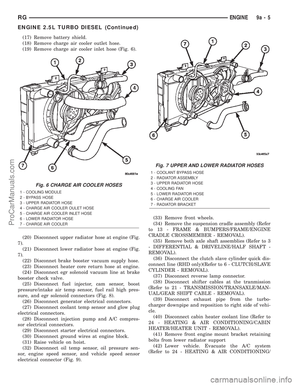
(19) Remove charge air cooler inlet hose (Fig. 6).
(20) Disconnect upper radiator hose at engine (Fig.
7).
(21) Disconnect lower radiator hose at engine (Fig.
7).
(22) Disconnet brake booster vacuum supply hose.
(23) Disconnect heater core return hose at engine.
(24) Disconnect egr solenoid vacuum line at brake
booster check valve.
(25) Disconnect fuel injector, cam sensor, boost
pressure/intake air temp sensor, fuel rail high pres-
sure, and egr solenoid connectors (Fig. 8).
(26) Disconnect generator electrical connectors.
(27) Disconnect coolant temp sensor and glow plug
electrical connectors.
(28) Disconnect injection pump and A/C compres-
sor electrical connectors.
(29) Disconnect starter electrical connectors.
(30) Disconnect ground wires at engine block.
(31) Raise vehicle on hoist.
(32) Disconnect oil temp sensor, oil pressure sen-
sor, engine speed sensor, and vehicle speed sensor
electrical connector (Fig. 9).(33) Remove front wheels.
(34) Remove the suspension cradle assembly (Refer
to 13 - FRAME & BUMPERS/FRAME/ENGINE
CRADLE CROSSMEMBER - REMOVAL).
(35) Remove both axle shaft assemblies (Refer to 3
- DIFFERENTIAL & DRIVELINE/HALF SHAFT -
REMOVAL).
(36) Disconnect the clutch slave cylinder quick dis-
connect line (RHD only)(Refer to 6 - CLUTCH/SLAVE
CYLINDER - REMOVAL).
(37) Disconnect reverse lamp connector.
(38) Disconnect shifter cables at the tranmission
(Refer to 21 - TRANSMISSION/TRANSAXLE/MAN-
UAL/GEAR SHIFT CABLE - REMOVAL).
(39) Disconnect exhaust pipe from the turbo-
charger downpipe and reposition to right side of vehi-
cle.
(40) Disconnect cabin heater coolant line (Refer to
24 - HEATING & AIR CONDITIONING/CABIN
HEATER/HEATER UNIT - REMOVAL).
(41) Remove front engine mount bracket retaining
bolts from lower radiator support
(42) Lower vehicle. Evacuate the A/C system
(Refer to 24 - HEATING & AIR CONDITIONING/
Fig. 6 CHARGE AIR COOLER HOSES
1 - COOLING MODULE
2 - BYPASS HOSE
3 - UPPER RADIATOR HOSE
4 - CHARGE AIR COOLER OULET HOSE
5 - CHARGE AIR COOLER INLET HOSE
6 - LOWER RADIATOR HOSE
7 - CHARGE AIR COOLER
Fig. 7 UPPER AND LOWER RADIATOR HOSES
1 - COOLANT BYPASS HOSE
2 - RADIATOR ASSEMBLY
3 - UPPER RADIATOR HOSE
4 - COOLING FAN
5 - LOWER RADIATOR HOSE
6 - CHARGE AIR COOLER
7 - RADIATOR BRACKET
RGENGINE9a-5
ENGINE 2.5L TURBO DIESEL (Continued)
ProCarManuals.com
Page 1382 of 2399

(23) Remove cylinder head assembly from engine
block (Fig. 18).
CLEANING
Thoroughly clean the engine cylinder head and cyl-
inder block mating surfaces. Clean the intake and
exhaust manifold and engine cylinder head mating
surfaces. Remove all gasket material and carbon.
Check to ensure that no coolant or foreign material
has fallen into the tappet bore area.
Remove the carbon deposits from the combustion
chambers and top of the pistons.
INSPECTION
Use a straightedge and feeler gauge to check the
flatness of the engine cylinder head and block mating
surfaces.
The minimum cylinder head thickness is 89.95mm
(3.541 in.).
INSTALLATION
CAUTION: Piston protrusion must be measured to
determine cylinder head gasket thickness if one or
more cylinder liners have been replaced (Refer to 9
- ENGINE/CYLINDER HEAD - STANDARD PROCE-
DURE).
NOTE: If cylinder liner(s) have not been removed,
the same thickness head gasket that was removed
can be used.
(1) Clean and inspect gasket mating surfaces.
(2) Position correct head gasket on engine block.
(3) Place cylinder head on engine block (Fig. 18).
CAUTION: New cylinder head bolts must be used.
(4) Tighten cylinder head bolts following procedure
below.
Cylinder Head Bolt Torquing Procedure
(1) Lubricate cylinder head bolts with engine oil.
(2) Torque bolts to 30N´m in numerical starting
with bolt #1 (Fig. 19).
(3) Tighten all bolts an additional 75É, starting
with bolt #4 then 5-6-7-8-9-10-1-2-3 (Fig. 19).
(4) Tighten all bolts an additional 50É in numerical
order starting with bolt #11 then 12-13-14-15-16-
17-18 (Fig. 19).
(5) Without loosening any bolts tighten all bolts an
additional 75É in the following seguence: 4-5-6-7-8-9-
10-1-2-3-11-12-13-14-15-16-17-18.
Fig. 18 CYLINDER HEAD ASSEMBLY
1 - VALVE SPRING
2 - CYLINDER HEAD BOLT
3 - GLOW PLUG
4 - COOLANT TEMPERATURE SENSOR
5 - CYLINDER HEAD ALIGNMENT DOWEL
6 - CYLINDER BLOCK
7 - CYLINDER LINER
8 - ENGINE BLOCK DECK
9 - CYLINDER HEAD GASKET
10 - CYLINDER HEAD
11 - ROCKER ARM AND LIFTER ASSEMBLY
Fig. 19 CYLINDER HEAD TORQUE SEQUENCE
RGENGINE9a-21
CYLINDER HEAD (Continued)
ProCarManuals.com