2002 CHRYSLER TOWN AND COUNTRY exhaust gasket
[x] Cancel search: exhaust gasketPage 293 of 2399

CONDITION POSSIBLE CAUSES CORRECTION
5. Coolant level low in the coolant
tank (air will build up in the cooling
system causing the thermostat to
open late).5. Check and correct coolant
leaks.
6. Cylinder head gasket leaking
allowing exhaust gases to enter the
cooling system causing the
thermostat to open late.6. (a) Check for cylinder head
gasket leaks with a
commercially available leak
tester. (b) Check for coolant in
engine oil. Inspect for white
steam emitting from exhaust
system. Repair as necessary.
7. Water pump impeller loose on
shaft.7. Check water pump and
replace as necessary.
8. Loose accessory drive belt (water
pump slipping).8. Check and correct as
necessary.
9. Air leak on the suction side of the
water pump allowing air to build up
in the cooling system causing the
thermostat to open late.9. Locate leak and repair as
necessary.
PRESSURE CAP IS
BLOWING OFF STEAM
AND/OR COOLANT.
TEMPERATURE GAUGE
READING MAY BE ABOVE
NORMAL BUT NOT HIGH.
COOLANT LEVEL MAY BE
HIGH IN COOLANT TANK1. Pressure relief valve in pressure/
vent cap is defective.1. Check condition of
pressure/vent cap and cap
seals.
2. Head gasket leak or cracked
cylinder head.2. Repair as necessary.
COOLANT LOSS TO THE
GROUND WITHOUT
PRESSURE CAP
BLOWOFF. GAUGE IS
READING HIGH OR HOT1. Coolant leaks in radiator, cooling
system hoses, water pump, or
engine.1. Pressure test cooling system
and repair as necessary.
HOSE OR HOSES
COLLAPSE WHEN
ENGINE IS COOLING1. Vacuum created in cooling system
on engine cool-down is not being
relieved through pressure/vent cap.1. Cap relief valve stuck.
Replace if necessary.
NOISY FAN 1. Cooling fan blades loose. 1. Replace cooling fan
assembly.
2. Cooling fan blades striking a
surrounding object.2. Locate point of fan blade
contact and repair as
necessary.
3. Air obstructions at radiator or A/C
condensor.3. Remove obstructions or
clean debris from radiator or
A/C condensor.
7a - 4 COOLING 2.5L TURBO DIESELRG
COOLING 2.5L TURBO DIESEL (Continued)
ProCarManuals.com
Page 309 of 2399

ENGINE COOLANT
THERMOSTAT
DESCRIPTION
A pellet-type thermostat controls the operating
temperature of the engine by controlling the amount
of coolant flow to the radiator (Fig. 9).
OPERATION
The thermostat starts to open at 80ÉC (176ÉF).
Above this temperature, coolant is allowed to flow to
the radiator. This provides quicker engine warmup
and overall temperature control.
The same thermostat is used for winter and sum-
mer seasons. An engine should not be operated with-
out a thermostat, except for servicing or testing.
Operating without a thermostat causes other prob-
lems. These are: longer engine warmup time, unreli-
able warmup performance, increased exhaust
emissions and crankcase condensation. This conden-
sation can result in sludge formation.
REMOVAL
NOTE: The thermostat is not serviced separately.
The thermostat and housing must be replaced as
an assembly.
(1) Disconnect negative battery cable.
(2) Drain cooling system (Refer to 7 - COOLING/
ENGINE/COOLANT - STANDARD PROCEDURE).
(3) Remove front wiper unit to gain access to ther-
mostat housing(Refer to 8 - ELECTRICAL/WIPERS/
WASHERS/WIPER MODULE - REMOVAL).
(4) Disconnect upper radiator hose adapter tube,
water pump hose, and EGR hose at thermostat hous-
ing.
(5) Remove both thermostat housing attaching
bolts and housing (Fig. 10).
INSTALLATION
(1) Install thermostat housing, gasket, and retain-
ing bolts (Fig. 10). Torque bolts to 27.5N´m.
(2) Connect upper radiator hose adapter tube,
water pump hose, and EGR cooler hose to thermostat
housing.
Fig. 8 COOLANT TEMPERATURE SENSOR
LOCATION
1 - EGR SOLENOID
2 - UPPER RADIATOR HOSE
3 - COOLANT TEMPERATURE SENSOR
4 - INTAKE MANIFOLD INLET
5 - INTAKE MANIFOLD/CYLINDER HEAD COVER
Fig. 9 THERMOSTAT HOUSING LOCATION
1 - CYLINDER HEAD COVER
2 - THERMOSTAT HOUSING
3 - AIR BLEED
4 - WATER PUMP
5 - WATER PUMP HOUSING TO THERMOSTAT HOUSING
BYPASS HOSE
6 - E G R VA LV E
7a - 20 ENGINERG
ENGINE COOLANT THERMOSTAT (Continued)
ProCarManuals.com
Page 1202 of 2399
ENGINE
TABLE OF CONTENTS
page page
ENGINE 2.4L.............................. 1ENGINE 3.3/3.8L......................... 74
ENGINE 2.4L
TABLE OF CONTENTS
page page
ENGINE 2.4L
DESCRIPTION..........................3
DIAGNOSIS AND TESTING
DIAGNOSIS AND TESTING - ENGINE
DIAGNOSIS - INTRODUCTION............3
DIAGNOSIS AND TESTING - ENGINE
DIAGNOSIS - PERFORMANCE............4
DIAGNOSIS AND TESTING - ENGINE
DIAGNOSIS - MECHANICAL..............6
DIAGNOSIS AND TESTING - ENGINE OIL
LEAK INSPECTION.....................8
DIAGNOSIS AND TESTING - CYLINDER
COMPRESSION PRESSURE TEST.........9
DIAGNOSIS AND TESTING - CYLINDER
COMBUSTION PRESSURE LEAKAGE
TEST................................9
STANDARD PROCEDURE
STANDARD PROCEDURE - ENGINE CORE
AND OIL GALLERY PLUGS..............10
STANDARD PROCEDURE - REPAIR OF
DAMAGED OR WORN THREADS.........10
STANDARD PROCEDURE - HYDROSTATIC
LOCKED ENGINE.....................10
STANDARD PROCEDURE - FORM-IN-
PLACE GASKETS AND SEALERS.........11
STANDARD PROCEDURE - ENGINE
GASKET SURFACE PREPARATION........11
STANDARD PROCEDURE - MEASURING
BEARING CLEARANCE USING
PLASTIGAGE........................12
REMOVAL - ENGINE ASSEMBLY...........12
INSTALLATION - ENGINE ASSEMBLY........16
SPECIFICATIONS
SPECIFICATIONS - 2.4L ENGINE.........17
SPECIFICATIONS - TORQUE............20
SPECIAL TOOLS
2.4L ENGINE.........................21AIR CLEANER ELEMENT
REMOVAL.............................24
INSTALLATION.........................24
AIR CLEANER HOUSING
REMOVAL.............................24
INSTALLATION.........................24
CYLINDER HEAD
DESCRIPTION.........................24
OPERATION...........................24
DIAGNOSIS AND TESTINGÐCYLINDER HEAD
GASKET............................24
REMOVAL - CYLINDER HEAD.............25
CLEANING............................26
INSPECTION..........................26
INSTALLATION - CYLINDER HEAD..........26
CAMSHAFT OIL SEAL(S)
REMOVAL.............................28
INSTALLATION.........................28
CAMSHAFT(S)
DESCRIPTION.........................29
OPERATION...........................29
STANDARD PROCEDURE - MEASURING
CAMSHAFT END PLAY.................29
REMOVAL.............................29
CLEANING............................29
INSPECTION..........................30
INSTALLATION.........................30
CYLINDER HEAD COVER
REMOVAL.............................31
CLEANING............................31
INSPECTION..........................31
INSTALLATION.........................31
INTAKE/EXHAUST VALVES & SEATS
DESCRIPTION.........................32
CLEANING............................32
RSENGINE9-1
ProCarManuals.com
Page 1204 of 2399
EXHAUST MANIFOLD
DESCRIPTION.........................62
OPERATION...........................62
REMOVAL.............................62
CLEANING............................62
INSPECTION..........................62
INSTALLATION.........................62
TIMING BELT COVER(S)
REMOVAL.............................63
INSTALLATION.........................63
TIMING BELT AND SPROCKET(S)
REMOVAL
REMOVAL - TIMING BELT...............64REMOVAL - CRANKSHAFT SPROCKET....66
CLEANING............................66
INSTALLATION
INSTALLATION - CRANKSHAFT SPROCKET . 66
INSTALLATION - TIMING BELT...........67
TIMING BELT TENSIONER & PULLEY
REMOVAL.............................68
INSTALLATION.........................69
BALANCE SHAFTS AND CARRIER ASSEMBLY
DESCRIPTION.........................69
OPERATION...........................70
REMOVAL.............................70
INSTALLATION.........................71
ENGINE 2.4L
DESCRIPTION
The 2.4 Liter (148 cu. in.) in-line four cylinder
engine is a double over head camshaft with hydraulic
lash adjusters and four valve per cylinder design.
The engine is free-wheeling; meaning it has provi-
sions for piston-to-valve clearance. However valve-to-
valve interference can occur, if camshafts are rotated
independently.
The cylinders are numbered from front of the
engine to the rear. The firing order is 1±3±4±2.
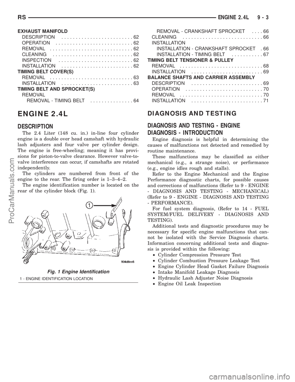
The engine identification number is located on the
rear of the cylinder block (Fig. 1).
DIAGNOSIS AND TESTING
DIAGNOSIS AND TESTING - ENGINE
DIAGNOSIS - INTRODUCTION
Engine diagnosis is helpful in determining the
causes of malfunctions not detected and remedied by
routine maintenance.
These malfunctions may be classified as either
mechanical (e.g., a strange noise), or performance
(e.g., engine idles rough and stalls).
Refer to the Engine Mechanical and the Engine
Performance diagnostic charts, for possible causes
and corrections of malfunctions (Refer to 9 - ENGINE
- DIAGNOSIS AND TESTING - MECHANICAL)
(Refer to 9 - ENGINE - DIAGNOSIS AND TESTING
- PERFORMANCE).
For fuel system diagnosis, (Refer to 14 - FUEL
SYSTEM/FUEL DELIVERY - DIAGNOSIS AND
TESTING).
Additional tests and diagnostic procedures may be
necessary for specific engine malfunctions that can-
not be isolated with the Service Diagnosis charts.
Information concerning additional tests and diagno-
sis is provided within the following:
²Cylinder Compression Pressure Test
²Cylinder Combustion Pressure Leakage Test
²Engine Cylinder Head Gasket Failure Diagnosis
²Intake Manifold Leakage Diagnosis
²Hydraulic Lash Adjuster Noise Diagnosis
²Engine Oil Leak Inspection
Fig. 1 Engine Identification
1 - ENGINE IDENTIFICATION LOCATION
RSENGINE 2.4L9-3
ProCarManuals.com
Page 1206 of 2399
CONDITION POSSIBLE CAUSE CORRECTION
ENGINE LOSS OF POWER 1. Dirty or incorrectly gapped plugs. 1. Clean plugs and set gap.
2. Contamination in fuel system. 2. Clean system and replace fuel
filter.
3. Faulty fuel pump. 3. Test and replace as necessary.
(Refer to Appropriate Diagnostic
Information)
4. Incorrect valve timing. 4. Correct valve timing.
5. Leaking cylinder head gasket. 5. Replace cylinder head gasket.
6. Low compression. 6. Test compression of each
cylinder.
7. Burned, warped, or pitted valves. 7. Replace valves.
8. Plugged or restricted exhaust
system.8. Perform exhaust restriction test.
(Refer to 11 - EXHAUST SYSTEM -
DIAGNOSIS AND TESTING) Install
new parts, as necessary.
9. Faulty ignition coil(s). 9. Test and replace as necessary.
(Refer to Appropriate Diagnostic
Information)
ENGINE MISSES ON
ACCELERATION1. Dirty or incorrectly gapped spark
plugs.1. Clean spark plugs and set gap.
2. Contamination in Fuel System. 2. Clean fuel system and replace
fuel filter.
3. Burned, warped, or pitted valves. 3. Replace valves.
4. Faulty ignition coil(s). 4. Test and replace as necessary.
(Refer to Appropriate Diagnostic
Information)
ENGINE MISSES AT HIGH SPEED 1. Dirty or incorrect spark plug gap. 1. Clean spark plugs and set gap.
2. Faulty ignition coil(s). 2. Test and replace as necessary.
(Refer to Appropriate Diagnostic
Information)
3. Dirty fuel injector(s). 3. Test and replace as necessary.
(Refer to Appropriate Diagnostic
Information)
4. Contamination in fuel system. 4. Clean system and replace fuel
filter.
RSENGINE 2.4L9-5
ENGINE 2.4L (Continued)
ProCarManuals.com
Page 1215 of 2399
(22) Remove engine front mount and bracket from
engine. (Refer to 9 - ENGINE/ENGINE MOUNTING/
FRONT MOUNT - REMOVAL)
(23) Remove structural collar. (Refer to 9 -
ENGINE/ENGINE BLOCK/STRUCTURAL COVER -
REMOVAL)
(24) Remove rear engine mount bracket. (Refer to
9 - ENGINE/ENGINE MOUNTING/REAR MOUNT -
REMOVAL)
(25) Mark flex plate to torque converter and
remove torque converter bolts.
(26) Pinch-off power steering supply hose at pump.
Remove hose from pump.
(27) Remove and set aside the power steering
pump and bracket. Do not disconnect pressure line.
(28) Lower vehicle.
(29) Remove A/C lines at compressor and cap open-
ings.
(30) Remove engine ground straps (strap at engine
right mount and at starter).
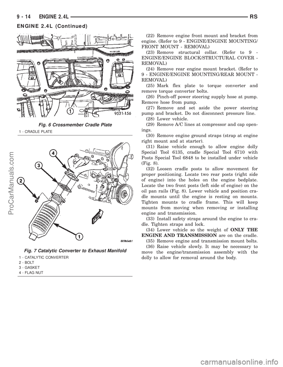
(31) Raise vehicle enough to allow engine dolly
Special Tool 6135, cradle Special Tool 6710 with
Posts Special Tool 6848 to be installed under vehicle
(Fig. 8).
(32) Loosen cradle posts to allow movement for
proper positioning. Locate two rear posts (right side
of engine) into the holes on the engine bedplate.
Locate the two front posts (left side of engine) on the
oil pan rails (Fig. 8). Lower vehicle and position cra-
dle mounts until the engine is resting on mounts.
Tighten mounts to cradle frame. This will keep
mounts from moving when removing or installing
engine and transmission.
(33) Install safety straps around the engine to cra-
dle. Tighten straps and lock.
(34) Lower vehicle so the weight ofONLY THE
ENGINE AND TRANSMISSIONare on the cradle.
(35) Remove engine and transmission mount bolts.
(36) Raise vehicle slowly. It may be necessary to
move the engine/transmission assembly with the
dolly to allow for removal around the body.
Fig. 6 Crossmember Cradle Plate
1 - CRADLE PLATE
Fig. 7 Catalytic Converter to Exhaust Manifold
1 - CATALYTIC CONVERTER
2 - BOLT
3 - GASKET
4 - FLAG NUT
9 - 14 ENGINE 2.4LRS
ENGINE 2.4L (Continued)
ProCarManuals.com
Page 1219 of 2399
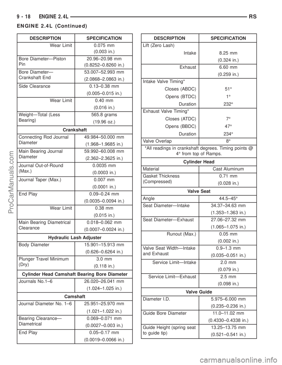
DESCRIPTION SPECIFICATION
Wear Limit 0.075 mm
(0.003 in.)
Bore DiameterÐPiston
Pin20.96±20.98 mm
(0.8252±0.8260 in.)
Bore DiameterÐ
Crankshaft End53.007±52.993 mm
(2.0868±2.0863 in.)
Side Clearance 0.13±0.38 mm
(0.005±0.015 in.)
Wear Limit 0.40 mm
(0.016 in.)
WeightÐTotal (Less
Bearing)565.8 grams
(19.96 oz.)
Crankshaft
Connecting Rod Journal
Diameter49.984±50.000 mm
(1.968±1.9685 in.)
Main Bearing Journal
Diameter59.992±60.008 mm
(2.362±2.3625 in.)
Journal Out-of-Round
(Max.)0.0035 mm
(0.0003 in.)
Journal Taper (Max.) 0.007 mm
(0.0001 in.)
End Play 0.09±0.24 mm
(0.0035±0.0094 in.)
Wear Limit 0.38 mm
(0.015 in.)
Main Bearing Diametrical
Clearance0.018±0.062 mm
(0.0007±0.0024 in.)
Hydraulic Lash Adjuster
Body Diameter 15.901±15.913 mm
(0.626±0.6264 in.)
Plunger Travel Minimum
(Dry)3.0 mm
(0.118 in.)
Cylinder Head Camshaft Bearing Bore Diameter
Journals No.1±6 26.020±26.041 mm
(1.024±1.025 in.)
Camshaft
Journal Diameter No. 1±6 25.951±25.970 mm
(1.021±1.022 in.)
Bearing ClearanceÐ
Diametrical0.069±0.071 mm
(0.0027±0.003 in.)
End Play 0.05±0.17 mm
(0.0019±0.0066 in.)DESCRIPTION SPECIFICATION
Lift (Zero Lash)
Intake 8.25 mm
(0.324 in.)
Exhaust 6.60 mm
(0.259 in.)
Intake Valve Timing*
Closes (ABDC) 51É
Opens (BTDC) 1É
Duration 232É
Exhaust Valve Timing*
Closes (ATDC) 7É
Opens (BBDC) 47É
Duration 234É
Valve Overlap 8É
*All readings in crankshaft degrees. Timing points @
4É from top of Ramps.
Cylinder Head
Material Cast Aluminum
Gasket Thickness
(Compressed)0.71 mm
(0.028 in.)
Valve Seat
Angle 44.5±45É
Seat DiameterÐIntake 34.37±34.63 mm
(1.353±1.363 in.)
Seat DiameterÐExhaust 27.06±27.32 mm
(1.065±1.075 in.)
Runout (Max.) 0.05 mm
(0.002 in.)
Valve Seat WidthÐIntake
and Exhaust0.9±1.3 mm
(0.035±0.051 in.)
Service LimitÐIntake 2.0 mm
(0.079 in.)
Service LimitÐExhaust 2.5 mm
(0.098 in.)
Valve Guide
Diameter I.D. 5.975±6.000 mm
(0.235±0.236 in.)
Guide Bore Diameter 11.0±11.02 mm
(0.4330±0.4338 in.)
Guide Height (spring seat
to guide tip)13.25±13.75 mm
(0.521±0.541 in.)
9 - 18 ENGINE 2.4LRS
ENGINE 2.4L (Continued)
ProCarManuals.com
Page 1225 of 2399
AIR CLEANER ELEMENT
REMOVAL
(1) Unsnap 2 clips.
(2) Lift cover and pull toward the engine and
remove cover tabs from air box.
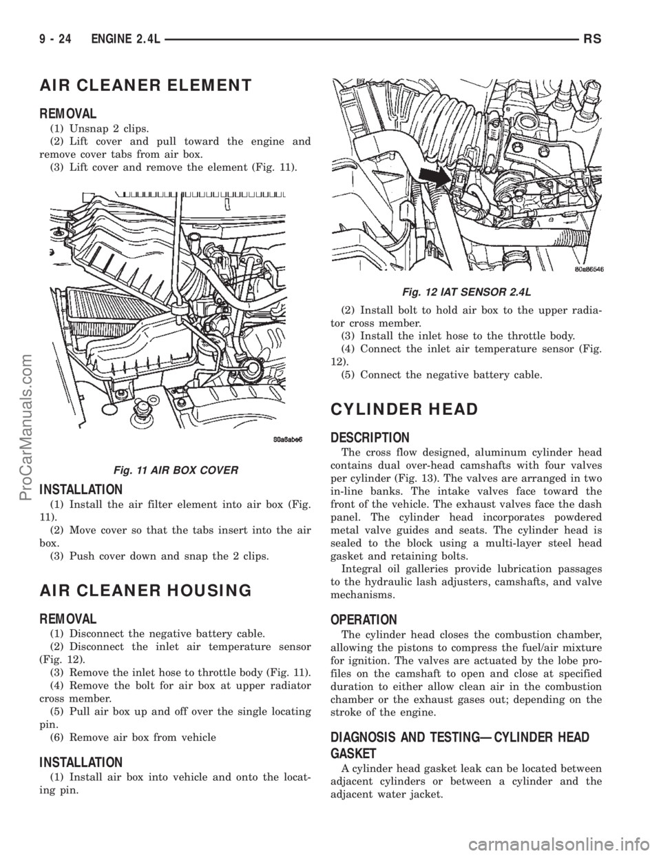
(3) Lift cover and remove the element (Fig. 11).
INSTALLATION
(1) Install the air filter element into air box (Fig.
11).
(2) Move cover so that the tabs insert into the air
box.
(3) Push cover down and snap the 2 clips.
AIR CLEANER HOUSING
REMOVAL
(1) Disconnect the negative battery cable.
(2) Disconnect the inlet air temperature sensor
(Fig. 12).
(3) Remove the inlet hose to throttle body (Fig. 11).
(4) Remove the bolt for air box at upper radiator
cross member.
(5) Pull air box up and off over the single locating
pin.
(6) Remove air box from vehicle
INSTALLATION
(1) Install air box into vehicle and onto the locat-
ing pin.(2) Install bolt to hold air box to the upper radia-
tor cross member.
(3) Install the inlet hose to the throttle body.
(4) Connect the inlet air temperature sensor (Fig.
12).
(5) Connect the negative battery cable.
CYLINDER HEAD
DESCRIPTION
The cross flow designed, aluminum cylinder head
contains dual over-head camshafts with four valves
per cylinder (Fig. 13). The valves are arranged in two
in-line banks. The intake valves face toward the
front of the vehicle. The exhaust valves face the dash
panel. The cylinder head incorporates powdered
metal valve guides and seats. The cylinder head is
sealed to the block using a multi-layer steel head
gasket and retaining bolts.
Integral oil galleries provide lubrication passages
to the hydraulic lash adjusters, camshafts, and valve
mechanisms.
OPERATION
The cylinder head closes the combustion chamber,
allowing the pistons to compress the fuel/air mixture
for ignition. The valves are actuated by the lobe pro-
files on the camshaft to open and close at specified
duration to either allow clean air in the combustion
chamber or the exhaust gases out; depending on the
stroke of the engine.
DIAGNOSIS AND TESTINGÐCYLINDER HEAD
GASKET
A cylinder head gasket leak can be located between
adjacent cylinders or between a cylinder and the
adjacent water jacket.
Fig. 11 AIR BOX COVER
Fig. 12 IAT SENSOR 2.4L
9 - 24 ENGINE 2.4LRS
ProCarManuals.com