2002 CHRYSLER TOWN AND COUNTRY Engine cylinder head rocker torque 3.8
[x] Cancel search: Engine cylinder head rocker torque 3.8Page 1275 of 2399
ENGINE 3.3/3.8L
TABLE OF CONTENTS
page page
ENGINE 3.3/3.8L
DESCRIPTION.........................76
DIAGNOSIS AND TESTING
DIAGNOSIS AND TESTING - ENGINE
DIAGNOSIS - INTRODUCTION...........77
DIAGNOSIS AND TESTING - ENGINE
DIAGNOSIS - PERFORMANCE...........78
DIAGNOSIS AND TESTING - ENGINE
DIAGNOSIS - MECHANICAL.............80
DIAGNOSIS AND TESTING - ENGINE OIL
LEAK INSPECTION....................82
DIAGNOSIS AND TESTING - CYLINDER
COMPRESSION PRESSURE TEST........83
DIAGNOSIS AND TESTING - CYLINDER
COMBUSTION PRESSURE LEAKAGE
TEST...............................83
STANDARD PROCEDURE
STANDARD PROCEDURE - MEASURING
BEARING CLEARANCE USING
PLASTIGAGE........................84
STANDARD PROCEDURE - FORM-IN-
PLACE GASKETS AND SEALERS.........84
STANDARD PROCEDURE - ENGINE
GASKET SURFACE PREPARATION........85
STANDARD PROCEDURE - HYDROSTATIC
LOCKED ENGINE.....................86
STANDARD PROCEDURE - REPAIR OF
DAMAGED OR WORN THREADS.........86
STANDARD PROCEDURE - ENGINE CORE
AND OIL GALLERY PLUGS..............86
REMOVAL - ENGINE ASSEMBLY...........87
INSTALLATION - ENGINE ASSEMBLY........90
SPECIFICATIONS
3.3/3.8L ENGINE......................92
SPECIFICATIONS - TORQUE............95
SPECIAL TOOLS
3.3/3.8L ENGINE......................96
AIR CLEANER ELEMENT
REMOVAL.............................99
INSTALLATION.........................99
AIR CLEANER HOUSING
REMOVAL.............................99
INSTALLATION........................100
CYLINDER HEAD
DESCRIPTION........................100
OPERATION..........................100
DIAGNOSIS AND TESTINGÐCYLINDER HEAD
GASKET...........................100
REMOVAL - CYLINDER HEAD............100
CLEANING...........................101INSPECTION.........................101
INSTALLATION - CYLINDER HEAD.........102
CYLINDER HEAD COVER(S)
DESCRIPTION........................103
CYLINDER HEAD COVER - RIGHT
REMOVAL............................103
INSTALLATION........................103
CYLINDER HEAD COVER - LEFT
REMOVAL............................105
INSTALLATION........................105
INTAKE/EXHAUST VALVES & SEATS
DESCRIPTION........................105
OPERATION..........................105
STANDARD PROCEDURE - REFACING
VALVESANDVALVESEATS ............105
REMOVAL............................106
CLEANING...........................106
INSPECTION.........................106
INSTALLATION........................107
VALVE SPRINGS
DESCRIPTION........................107
OPERATION..........................107
REMOVAL
REMOVAL - CYLINDER HEAD OFF.......108
REMOVAL - CYLINDER HEAD ON........108
INSPECTION.........................109
INSTALLATION
INSTALLATION - CYLINDER HEAD OFF . . . 109
INSTALLATION - CYLINDER HEAD ON....109
ROCKER ARMS
DESCRIPTION
DESCRIPTION - ROCKER ARMS.........110
DESCRIPTION - PUSHRODS............110
OPERATION
OPERATION - ROCKER ARMS..........110
OPERATION - PUSHRODS.............110
REMOVAL - ROCKER ARMS AND SHAFT....110
DISASSEMBLY - ROCKER ARMS AND
SHAFT.............................110
ASSEMBLY - ROCKER ARMS AND SHAFT . . . 111
INSTALLATION - ROCKER ARMS AND
SHAFT.............................111
VALVE STEM SEALS
DESCRIPTION........................112
REMOVAL............................113
INSTALLATION........................113
ENGINE BLOCK
DESCRIPTION........................113
STANDARD PROCEDURE - CYLINDER BORE
HONING............................113
9 - 74 ENGINE 3.3/3.8LRS
ProCarManuals.com
Page 1304 of 2399
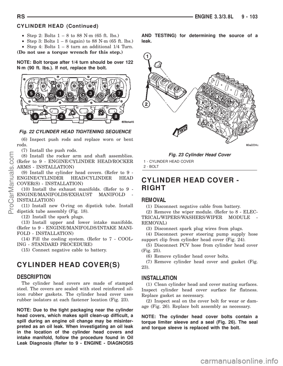
²Step 2: Bolts1±8to88N´m(65ft.lbs.)
²Step 3: Bolts1±8(again) to 88 N´m (65 ft. lbs.)
²Step 4: Bolts1±8turn an additional 1/4 Turn.
(Do not use a torque wrench for this step.)
NOTE: Bolt torque after 1/4 turn should be over 122
N´m (90 ft. lbs.). If not, replace the bolt.
(6) Inspect push rods and replace worn or bent
rods.
(7) Install the push rods.
(8) Install the rocker arm and shaft assemblies.
(Refer to 9 - ENGINE/CYLINDER HEAD/ROCKER
ARMS - INSTALLATION)
(9) Install the cylinder head covers. (Refer to 9 -
ENGINE/CYLINDER HEAD/CYLINDER HEAD
COVER(S) - INSTALLATION)
(10) Install the exhaust manifolds. (Refer to 9 -
ENGINE/MANIFOLDS/EXHAUST MANIFOLD -
INSTALLATION)
(11) Install new O-ring on dipstick tube. Install
dipstick tube assembly (Fig. 18).
(12) Install the spark plugs.
(13) Install upper and lower intake manifolds.
(Refer to 9 - ENGINE/MANIFOLDS/INTAKE MANI-
FOLD - INSTALLATION)
(14) Fill the cooling system. (Refer to 7 - COOL-
ING - STANDARD PROCEDURE)
(15) Connect negative cable to battery.
CYLINDER HEAD COVER(S)
DESCRIPTION
The cylinder head covers are made of stamped
steel. The covers are sealed with steel reinforced sil-
icon rubber gaskets. The cylinder head cover uses
rubber isolators at each fastener location (Fig. 23).
NOTE: Due to the tight packaging near the cylinder
head covers, which makes spill clean-up difficult, a
spill during an engine oil change may be misinter-
preted as an oil leak. When investigating an oil leak
in the location of the cylinder head covers and
intake manifold, follow the procedure found in Oil
Leak Diagnosis (Refer to 9 - ENGINE - DIAGNOSISAND TESTING) for determining the source of a
leak.
CYLINDER HEAD COVER -
RIGHT
REMOVAL
(1) Disconnect negative cable from battery.
(2) Remove the wiper module. (Refer to 8 - ELEC-
TRICAL/WIPERS/WASHERS/WIPER MODULE -
REMOVAL)
(3) Disconnect spark plug wires from plugs.
(4) Disconnect power steering pump supply hose
support clip from cylinder head cover (Fig. 24).
(5) Disconnect PCV hose from cylinder head cover
(Fig. 25).
(6) Remove cylinder head cover bolts.
(7) Remove cylinder head cover and gasket (Fig.
23).
INSTALLATION
(1) Clean cylinder head and cover mating surfaces.
Inspect cylinder head cover surface for flatness.
Replace gasket as necessary.
(2) Inspect seal on the cover bolt for wear or dam-
age (Fig. 26). Replace bolt assembly as necessary.
NOTE: The cylinder head cover bolts contain a
torque limiter sleeve and a seal (Fig. 26). The seal
and torque sleeve is replaced with the bolt.
Fig. 22 CYLINDER HEAD TIGHTENING SEQUENCE
Fig. 23 Cylinder Head Cover
1 - CYLINDER HEAD COVER
2 - BOLT
RSENGINE 3.3/3.8L9 - 103
CYLINDER HEAD (Continued)
ProCarManuals.com
Page 1327 of 2399
the plunger and the lifter body causing the plunger
to stick in the down position. This heavy click will be
accompanied by excessive clearance between the
valve stem and rocker arm as valve closes. In either
case, lifter assembly should be removed for inspec-
tion.
REMOVAL
(1) Remove the cylinder head(s). (Refer to 9 -
ENGINE/CYLINDER HEAD - REMOVAL)
(2) Remove the yoke retainer and aligning yokes
(Fig. 73).
(3) Remove the hydraulic lifters. If necessary use
Special Tool C-4129, or equivalent to remove lifters
from bores. If lifters are to be reused, identify each
lifter to ensure installation in original location.
INSTALLATION
(1) Lubricate the lifters with engine oil.
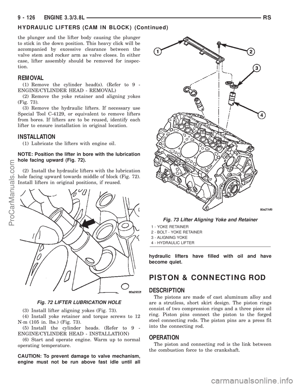
NOTE: Position the lifter in bore with the lubrication
hole facing upward (Fig. 72).
(2) Install the hydraulic lifters with the lubrication
hole facing upward towards middle of block (Fig. 72).
Install lifters in original positions, if reused.
(3) Install lifter aligning yokes (Fig. 73).
(4) Install yoke retainer and torque screws to 12
N´m (105 in. lbs.) (Fig. 73).
(5) Install the cylinder heads. (Refer to 9 -
ENGINE/CYLINDER HEAD - INSTALLATION)
(6) Start and operate engine. Warm up to normal
operating temperature.
CAUTION: To prevent damage to valve mechanism,
engine must not be run above fast idle until allhydraulic lifters have filled with oil and have
become quiet.
PISTON & CONNECTING ROD
DESCRIPTION
The pistons are made of cast aluminum alloy and
are a strutless, short skirt design. The piston rings
consist of two compression rings and a three piece oil
ring. Piston pins connect the piston to the forged
steel connecting rods. The piston pins are a press fit
into the connecting rod.
OPERATION
The piston and connecting rod is the link between
the combustion force to the crankshaft.
Fig. 72 LIFTER LUBRICATION HOLE
Fig. 73 Lifter Aligning Yoke and Retainer
1 - YOKE RETAINER
2 - BOLT - YOKE RETAINER
3 - ALIGNING YOKE
4 - HYDRAULIC LIFTER
9 - 126 ENGINE 3.3/3.8LRS
HYDRAULIC LIFTERS (CAM IN BLOCK) (Continued)
ProCarManuals.com
Page 1356 of 2399
(3) Position heat shield on manifold (Fig. 136).
(4) Install the remaining manifold attaching bolts.
Tighten all bolts to 23 N´m (200 in. lbs.).
(5) Install and tighten heat shield attaching nut to
12 N´m (105 in. lbs.) (Fig. 136).
(6) Connect battery negative cable.
VALVE TIMING
STANDARD PROCEDURE
STANDARD PROCEDURE - VALVE TIMING
VERIFICATION
(1) Remove front cylinder head cover and all 6
spark plugs.
(2) Rotate engine until the #2 piston is at TDC of
the compression stroke.
(3) Install a degree wheel on the crankshaft pulley.
(4) With proper adaptor, install a dial indicator
into #2 spark plug hole. Using the indicator find TDC
on the compression stroke.
(5) Position the degree wheel to zero.
(6) Remove dial indicator from spark plug hole.
(7) Place a 5.08 mm (0.200 in.) spacer between the
valve stem tip of #2 intake valve and rocker arm pad.
Allow tappet to bleed down to give a solid tappet
effect.
(8) Install a dial indicator so plunger contacts the
#2 intake valve spring retainer as nearly perpendic-
ular as possible. Zero the indicator.
(9) Rotate the engine clockwise until the intake
valve has lifted .254 mm (0.010 in.).
CAUTION: Do not turn crankshaft any further clock-
wise as intake valve might bottom and result in
serious damage.
(10) Degree wheel should read 6 degrees BTDC to
6 degrees ATDC.
STANDARD PROCEDURE - MEASURING
TIMING CHAIN WEAR
NOTE: This procedure must be performed with the
timing chain cover removed (Refer to 9 - ENGINE/
VALVE TIMING/TIMING CHAIN COVER - REMOVAL).
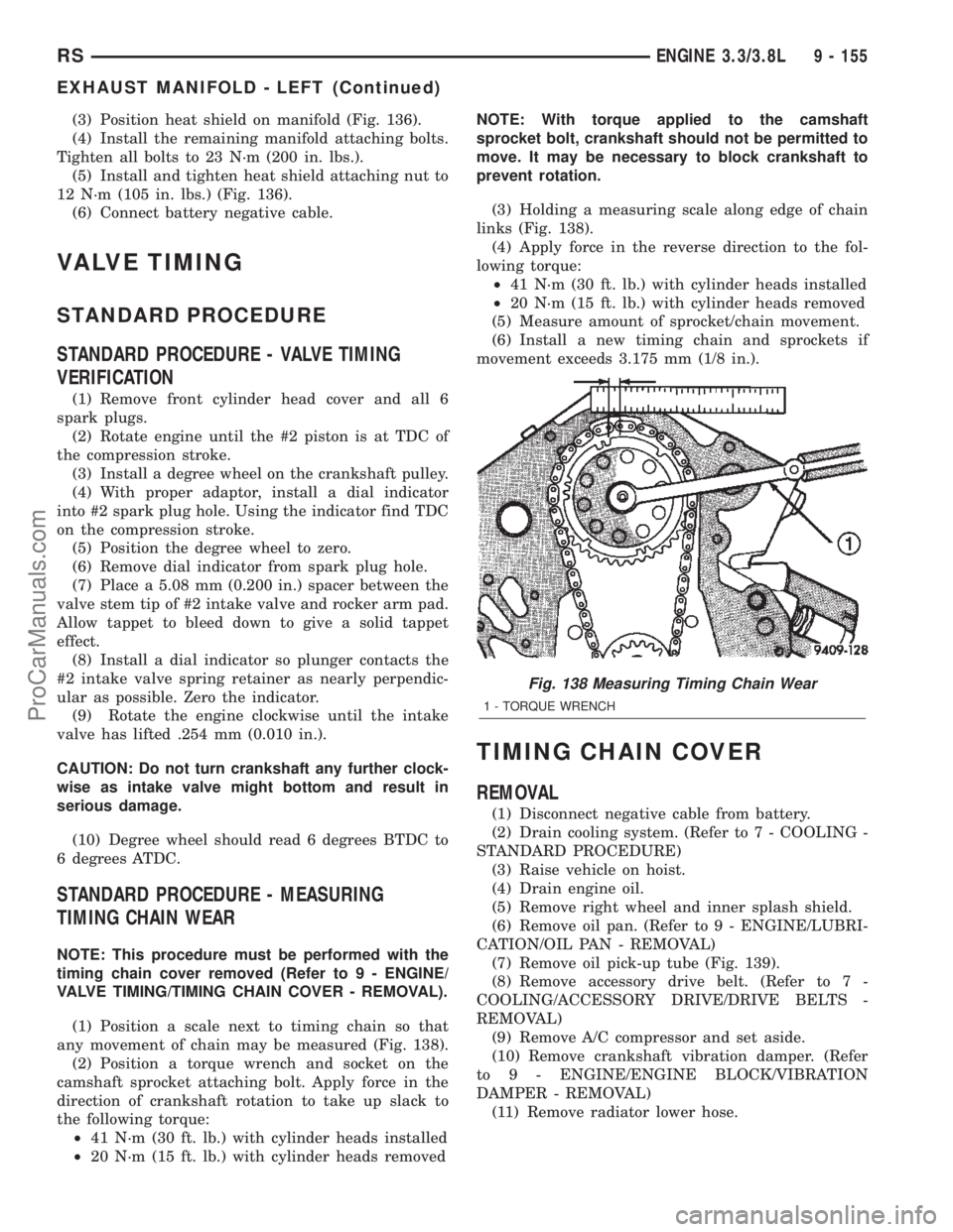
(1) Position a scale next to timing chain so that
any movement of chain may be measured (Fig. 138).
(2) Position a torque wrench and socket on the
camshaft sprocket attaching bolt. Apply force in the
direction of crankshaft rotation to take up slack to
the following torque:
²41 N´m (30 ft. lb.) with cylinder heads installed
²20 N´m (15 ft. lb.) with cylinder heads removedNOTE: With torque applied to the camshaft
sprocket bolt, crankshaft should not be permitted to
move. It may be necessary to block crankshaft to
prevent rotation.
(3) Holding a measuring scale along edge of chain
links (Fig. 138).
(4) Apply force in the reverse direction to the fol-
lowing torque:
²41 N´m (30 ft. lb.) with cylinder heads installed
²20 N´m (15 ft. lb.) with cylinder heads removed
(5) Measure amount of sprocket/chain movement.
(6) Install a new timing chain and sprockets if
movement exceeds 3.175 mm (1/8 in.).
TIMING CHAIN COVER
REMOVAL
(1) Disconnect negative cable from battery.
(2) Drain cooling system. (Refer to 7 - COOLING -
STANDARD PROCEDURE)
(3) Raise vehicle on hoist.
(4) Drain engine oil.
(5) Remove right wheel and inner splash shield.
(6) Remove oil pan. (Refer to 9 - ENGINE/LUBRI-
CATION/OIL PAN - REMOVAL)
(7) Remove oil pick-up tube (Fig. 139).
(8) Remove accessory drive belt. (Refer to 7 -
COOLING/ACCESSORY DRIVE/DRIVE BELTS -
REMOVAL)
(9) Remove A/C compressor and set aside.
(10) Remove crankshaft vibration damper. (Refer
to 9 - ENGINE/ENGINE BLOCK/VIBRATION
DAMPER - REMOVAL)
(11) Remove radiator lower hose.
Fig. 138 Measuring Timing Chain Wear
1 - TORQUE WRENCH
RSENGINE 3.3/3.8L9 - 155
EXHAUST MANIFOLD - LEFT (Continued)
ProCarManuals.com