2002 CHRYSLER TOWN AND COUNTRY wipers
[x] Cancel search: wipersPage 2043 of 2399
HOOD
TABLE OF CONTENTS
page page
HINGE
REMOVAL.............................60
INSTALLATION.........................60
HOOD
REMOVAL.............................60
INSTALLATION.........................61
LATCH
REMOVAL.............................61INSTALLATION.........................61
LATCH RELEASE CABLE
REMOVAL.............................61
INSTALLATION.........................62
LATCH STRIKER
REMOVAL.............................62
INSTALLATION.........................62
HINGE
REMOVAL
(1) Remove Front Wiper Unit (Refer to 8 - ELEC-
TRICAL/WIPERS/WASHERS/WIPER MODULE -
REMOVAL) for procedure.
(2) Raise hood.
(3) Mark all bolt and hinge attachment locations
with a grease pencil or other suitable device to pro-
vide reference marks for installation.
(4) Remove pivot bolt from the body half of hood
hinge and use suitable device to support the hood.
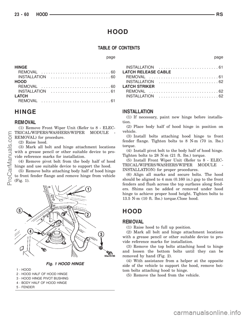
(5) Remove bolts attaching body half of hood hinge
to front fender flange and remove hinge from vehicle
(Fig. 1).
INSTALLATION
(1) If necessary, paint new hinge before installa-
tion.
(2) Place body half of hood hinge in position on
vehicle.
(3) Install bolts attaching hood hinge to front
fender flange. Tighten bolts to 8 N´m (70 in. lbs.)
torque.
(4) Install pivot bolt to the body half of hood hinge.
Tighten bolts to 28 N´m (21 ft. lbs.) torque.
(5) Install Front Wiper Unit (Refer to 8 - ELEC-
TRICAL/WIPERS/WASHERS/WIPER MODULE -
INSTALLATION) for proper procedures.
(6) Align all marks and secure bolts. The hood
should be aligned to 4 mm (0.160 in.) gap to the front
fenders and flush across the top surfaces along fend-
ers. Shims can be added or removed under hood
hinge to achieve proper hood height. Tighten bolts to
13.5 N´m (10 ft. lbs.) torque.Close hood.
HOOD
REMOVAL
(1) Raise hood to full up position.
(2) Mark all bolt and hinge attachment locations
with a grease pencil or other suitable device to pro-
vide reference marks for installation.
(3) Remove the top bolts attaching hood to hinge
and loosen the bottom bolts until they can be
removed by hand (Fig. 2).
(4) With assistance from a helper at the opposite
side of the vehicle to support the hood, remove bot-
tom bolts attaching hood to hinge.
(5) Remove the hood from the vehicle.
Fig. 1 HOOD HINGE
1 - HOOD
2 - HOOD HALF OF HOOD HINGE
3 - HOOD HINGE PIVOT BUSHING
4 - BODY HALF OF HOOD HINGE
5 - FENDER
23 - 60 HOODRS
ProCarManuals.com
Page 2092 of 2399
(15) Clean access urethane from exterior with
MopartSuper Kleen or equivalent.
(16) Apply 150 mm (6 in.) lengths of 50 mm (2 in.)
masking tape spaced 250 mm (10 in.) apart to hold
molding in place until urethane cures.
(17) Engage wire connectors to windshield
defroster grid.
(18) Install A-pillar trim panels.
(19) Install cowl cover and wipers.
(20) Install inside rear view mirror.
(21) After urethane has cured, remove tape strips
and water test windshield to verify repair.SLIDING DOOR GLASS
REMOVAL
The temperature of the vehicle should be at least
21É C (70É F) before removing the stationary quarter/
sliding door glass. Butyl sealer becomes more pliable
at high temperatures.
(1) Remove interior trim as necessary to gain
access attaching locations on back of glass.
(2) Remove nuts holding stationary glass to fence.
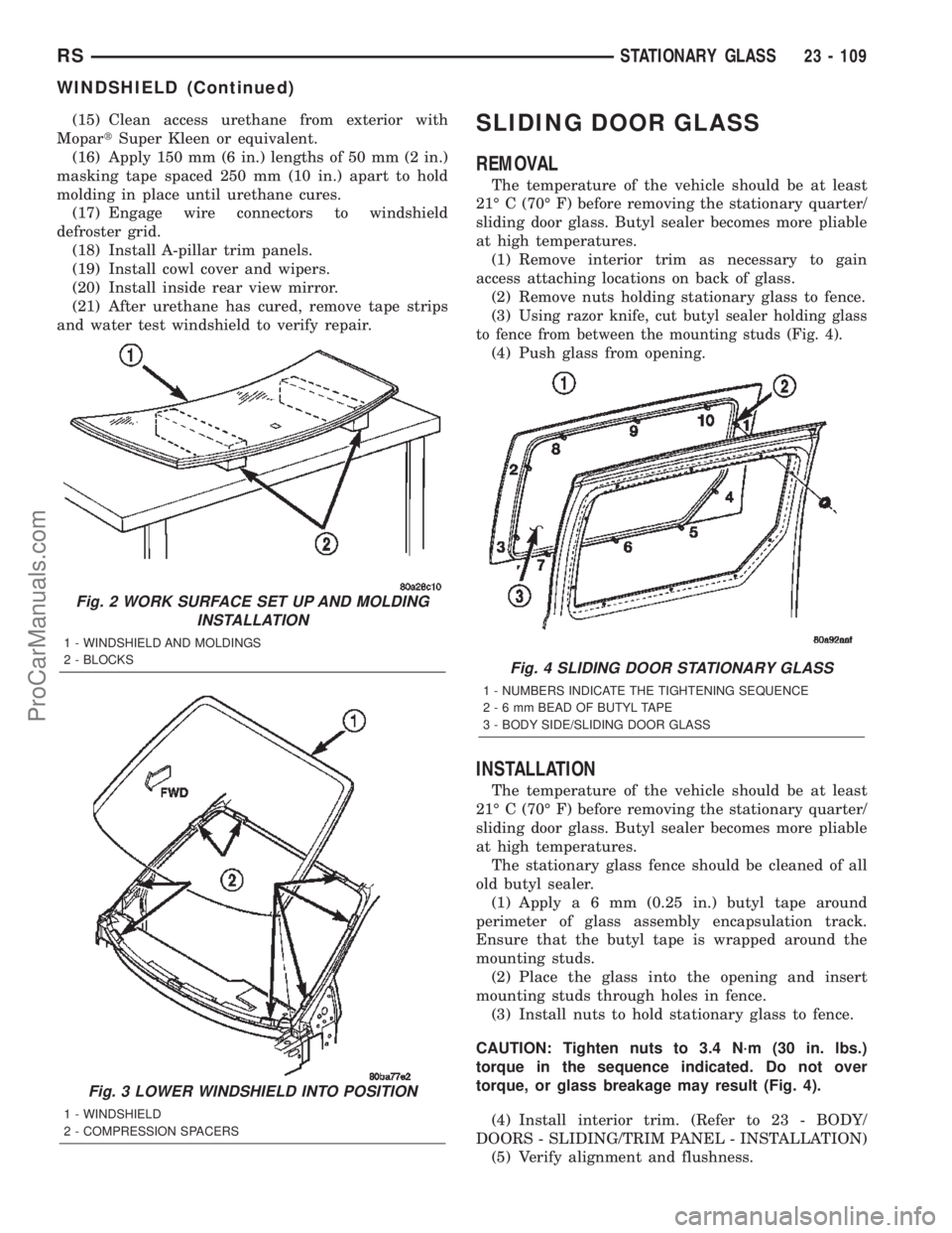
(3)
Using razor knife, cut butyl sealer holding glass
to fence from between the mounting studs (Fig. 4).
(4) Push glass from opening.
INSTALLATION
The temperature of the vehicle should be at least
21É C (70É F) before removing the stationary quarter/
sliding door glass. Butyl sealer becomes more pliable
at high temperatures.
The stationary glass fence should be cleaned of all
old butyl sealer.
(1) Applya6mm(0.25 in.) butyl tape around
perimeter of glass assembly encapsulation track.
Ensure that the butyl tape is wrapped around the
mounting studs.
(2) Place the glass into the opening and insert
mounting studs through holes in fence.
(3) Install nuts to hold stationary glass to fence.
CAUTION: Tighten nuts to 3.4 N´m (30 in. lbs.)
torque in the sequence indicated. Do not over
torque, or glass breakage may result (Fig. 4).
(4) Install interior trim. (Refer to 23 - BODY/
DOORS - SLIDING/TRIM PANEL - INSTALLATION)
(5) Verify alignment and flushness.
Fig. 2 WORK SURFACE SET UP AND MOLDING
INSTALLATION
1 - WINDSHIELD AND MOLDINGS
2 - BLOCKS
Fig. 3 LOWER WINDSHIELD INTO POSITION
1 - WINDSHIELD
2 - COMPRESSION SPACERS
Fig. 4 SLIDING DOOR STATIONARY GLASS
1 - NUMBERS INDICATE THE TIGHTENING SEQUENCE
2-6mmBEAD OF BUTYL TAPE
3 - BODY SIDE/SLIDING DOOR GLASS
RSSTATIONARY GLASS23 - 109
WINDSHIELD (Continued)
ProCarManuals.com
Page 2266 of 2399
The evaporator temperature sensor cannot be
adjusted or repaired and, if faulty or damaged, it
must be replaced.
OPERATION
The evaporator temperature sensor monitors the
temperature of the evaporator through its connection
to the top of the expansion valve. The sensor will
change its internal resistance in response to the tem-
peratures it monitors. The heater-A/C control module
is connected to the sensor through a sensor ground
circuit and a sensor signal circuit. As the evaporator
temperature increases, the resistance of the sensor
decreases and the voltage monitored by the module
decreases. The module uses this monitored voltage
reading to an indication of the evaporator tempera-
ture. The heater-A/C control module is programmed
to respond to this input by sending electronic mes-
sages to the Powertrain Control Module (PCM) over
the Programmable Communications Interface (PCI)
data bus, and the PCM then cycles the air condition-
ing compressor clutch as necessary to optimize air
conditioning system performance and to protect the
system from evaporator freezing. The external loca-
tion of the sensor and the use of a screw allows the
sensor to be removed or installed from the expansion
valve without disturbing the refrigerant in the sys-
tem. The evaporator temperature sensor is diagnosed
using a DRBIIItscan tool. Refer to the appropriate
diagnostic information.
REMOVAL
(1) Disconnect and isolate the battery negative
cable.
(2) Remove the air cleaner housing from the right
side of the engine compartment.
(3) Remove the windshield wiper assembly from
the vehicle(Refer to 8 - ELECTRICAL/WIPERS/
WASHERS/WIPER MODULE - REMOVAL).
(4) Remove the temperature sensor attaching
screw from the expansion valve.
(5) Pull the evaporator temperature sensor away
from the expansion valve far enough to access the
red release ring on the wiring connector. Push the
red ring toward the connector to release lock and
remove the HVAC wire harness connector from the
temperature sensor.
(6) Remove the evaporator temperature sensor
from the engine compartment. Please note that any
grease removed with the old temperature sensor
must be replaced, failure to do so could result in poor
a/c performance.
INSTALLATION
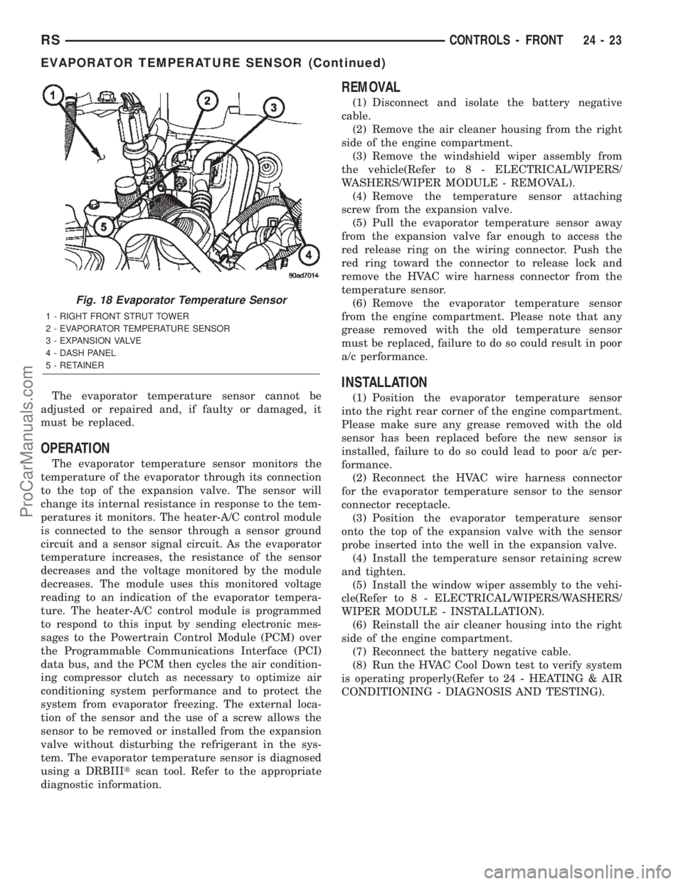
(1) Position the evaporator temperature sensor
into the right rear corner of the engine compartment.
Please make sure any grease removed with the old
sensor has been replaced before the new sensor is
installed, failure to do so could lead to poor a/c per-
formance.
(2) Reconnect the HVAC wire harness connector
for the evaporator temperature sensor to the sensor
connector receptacle.
(3) Position the evaporator temperature sensor
onto the top of the expansion valve with the sensor
probe inserted into the well in the expansion valve.
(4) Install the temperature sensor retaining screw
and tighten.
(5) Install the window wiper assembly to the vehi-
cle(Refer to 8 - ELECTRICAL/WIPERS/WASHERS/
WIPER MODULE - INSTALLATION).
(6) Reinstall the air cleaner housing into the right
side of the engine compartment.
(7) Reconnect the battery negative cable.
(8) Run the HVAC Cool Down test to verify system
is operating properly(Refer to 24 - HEATING & AIR
CONDITIONING - DIAGNOSIS AND TESTING).
Fig. 18 Evaporator Temperature Sensor
1 - RIGHT FRONT STRUT TOWER
2 - EVAPORATOR TEMPERATURE SENSOR
3 - EXPANSION VALVE
4 - DASH PANEL
5 - RETAINER
RSCONTROLS - FRONT24-23
EVAPORATOR TEMPERATURE SENSOR (Continued)
ProCarManuals.com
Page 2391 of 2399
VA LV E
DESCRIPTION
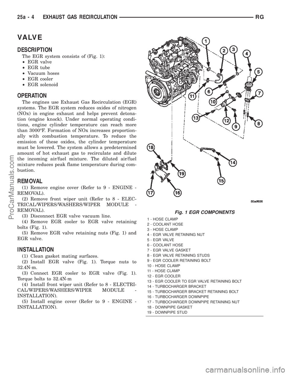
The EGR system consists of (Fig. 1):
²EGR valve
²EGR tube
²Vacuum hoses
²EGR cooler
²EGR solenoid
OPERATION
The engines use Exhaust Gas Recirculation (EGR)
systems. The EGR system reduces oxides of nitrogen
(NOx) in engine exhaust and helps prevent detona-
tion (engine knock). Under normal operating condi-
tions, engine cylinder temperature can reach more
than 3000ÉF. Formation of NOx increases proportion-
ally with combustion temperature. To reduce the
emission of these oxides, the cylinder temperature
must be lowered. The system allows a predetermined
amount of hot exhaust gas to recirculate and dilute
the incoming air/fuel mixture. The diluted air/fuel
mixture reduces peak flame temperature during com-
bustion.
REMOVAL
(1) Remove engine cover (Refer to 9 - ENGINE -
REMOVAL).
(2) Remove front wiper unit (Refer to 8 - ELEC-
TRICAL/WIPERS/WASHERS/WIPER MODULE -
REMOVAL).
(3) Disconnect EGR valve vacuum line.
(4) Remove EGR cooler to EGR valve retaining
bolts (Fig. 1).
(5) Remove EGR valve retaining nuts (Fig. 1) and
EGR valve.
INSTALLATION
(1) Clean gasket mating surfaces.
(2) Install EGR valve (Fig. 1). Torque nuts to
32.4N´m.
(3) Connect EGR cooler to EGR valve (Fig. 1).
Torque bolts to 32.4N´m
(4) Install front wiper unit (Refer to 8 - ELECTRI-
CAL/WIPERS/WASHERS/WIPER MODULE -
INSTALLATION).
(5) Install engine cover (Refer to 9 - ENGINE -
INSTALLATION).
Fig. 1 EGR COMPONENTS
1 - HOSE CLAMP
2 - COOLANT HOSE
3 - HOSE CLAMP
4 - EGR VALVE RETAINING NUT
5 - E G R VA LV E
6 - COOLANT HOSE
7 - EGR VALVE GASKET
8 - EGR VALVE RETAINING STUDS
9 - EGR COOLER RETAINING BOLT
10 - HOSE CLAMP
11 - HOSE CLAMP
12 - EGR COOLER
13 - EGR COOLER TO EGR VALVE RETAINING BOLT
14 - TURBOCHARGER BRACKET
15 - TURBOCHARGER BRACKET RETAINING BOLT
16 - TURBOCHARGER DOWNPIPE
17 - TURBOCHARGER DOWNPIPE RETAINING NUT
18 - DOWNPIPE GASKET
19 - DOWNPIPE STUD
25a - 4 EXHAUST GAS RECIRCULATIONRG
ProCarManuals.com
Page 2392 of 2399
VALVE COOLER
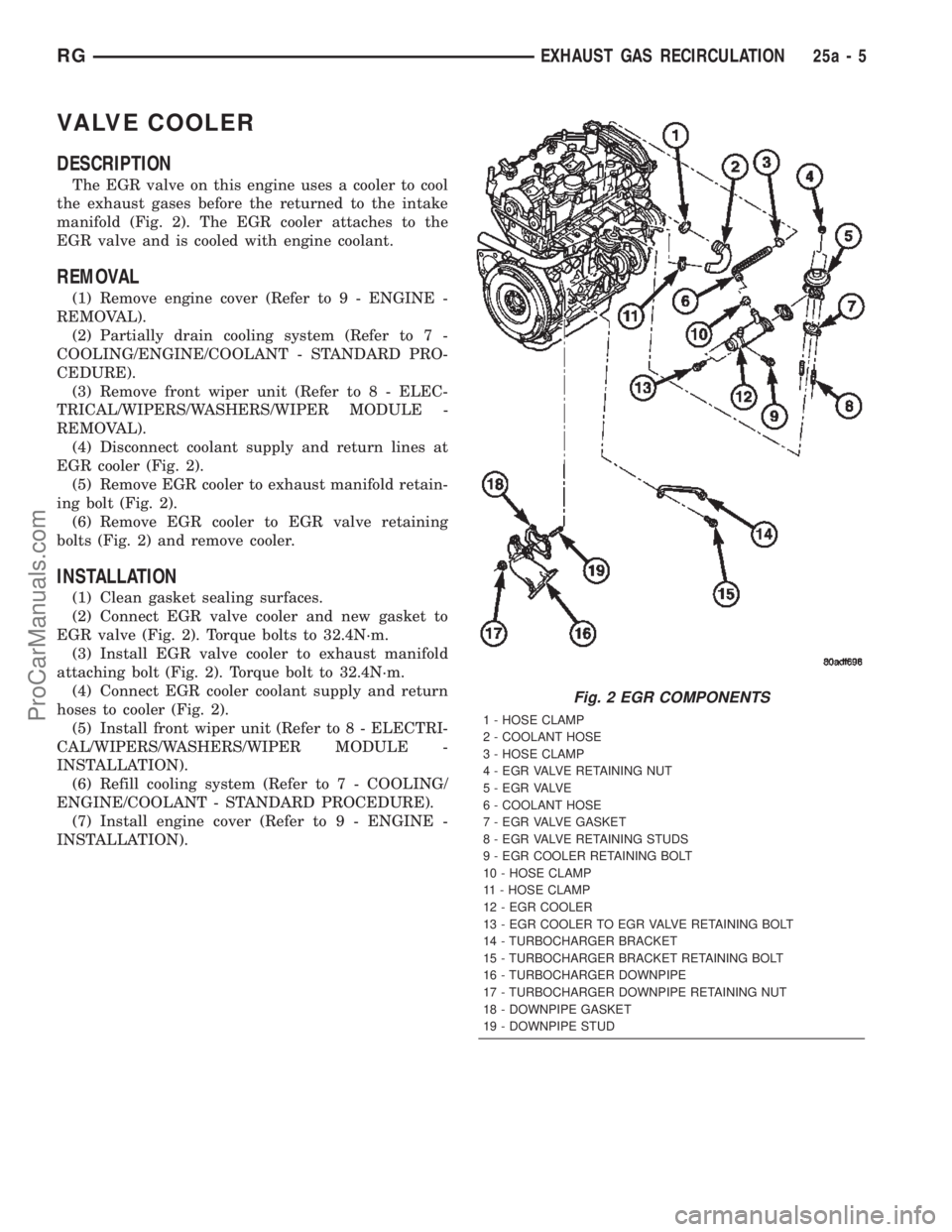
DESCRIPTION
The EGR valve on this engine uses a cooler to cool
the exhaust gases before the returned to the intake
manifold (Fig. 2). The EGR cooler attaches to the
EGR valve and is cooled with engine coolant.
REMOVAL
(1) Remove engine cover (Refer to 9 - ENGINE -
REMOVAL).
(2) Partially drain cooling system (Refer to 7 -
COOLING/ENGINE/COOLANT - STANDARD PRO-
CEDURE).
(3) Remove front wiper unit (Refer to 8 - ELEC-
TRICAL/WIPERS/WASHERS/WIPER MODULE -
REMOVAL).
(4) Disconnect coolant supply and return lines at
EGR cooler (Fig. 2).
(5) Remove EGR cooler to exhaust manifold retain-
ing bolt (Fig. 2).
(6) Remove EGR cooler to EGR valve retaining
bolts (Fig. 2) and remove cooler.
INSTALLATION
(1) Clean gasket sealing surfaces.
(2) Connect EGR valve cooler and new gasket to
EGR valve (Fig. 2). Torque bolts to 32.4N´m.
(3) Install EGR valve cooler to exhaust manifold
attaching bolt (Fig. 2). Torque bolt to 32.4N´m.
(4) Connect EGR cooler coolant supply and return
hoses to cooler (Fig. 2).
(5) Install front wiper unit (Refer to 8 - ELECTRI-
CAL/WIPERS/WASHERS/WIPER MODULE -
INSTALLATION).
(6) Refill cooling system (Refer to 7 - COOLING/
ENGINE/COOLANT - STANDARD PROCEDURE).
(7) Install engine cover (Refer to 9 - ENGINE -
INSTALLATION).
Fig. 2 EGR COMPONENTS
1 - HOSE CLAMP
2 - COOLANT HOSE
3 - HOSE CLAMP
4 - EGR VALVE RETAINING NUT
5 - E G R VA LV E
6 - COOLANT HOSE
7 - EGR VALVE GASKET
8 - EGR VALVE RETAINING STUDS
9 - EGR COOLER RETAINING BOLT
10 - HOSE CLAMP
11 - HOSE CLAMP
12 - EGR COOLER
13 - EGR COOLER TO EGR VALVE RETAINING BOLT
14 - TURBOCHARGER BRACKET
15 - TURBOCHARGER BRACKET RETAINING BOLT
16 - TURBOCHARGER DOWNPIPE
17 - TURBOCHARGER DOWNPIPE RETAINING NUT
18 - DOWNPIPE GASKET
19 - DOWNPIPE STUD
RGEXHAUST GAS RECIRCULATION25a-5
ProCarManuals.com