2002 CHRYSLER TOWN AND COUNTRY chain
[x] Cancel search: chainPage 1272 of 2399
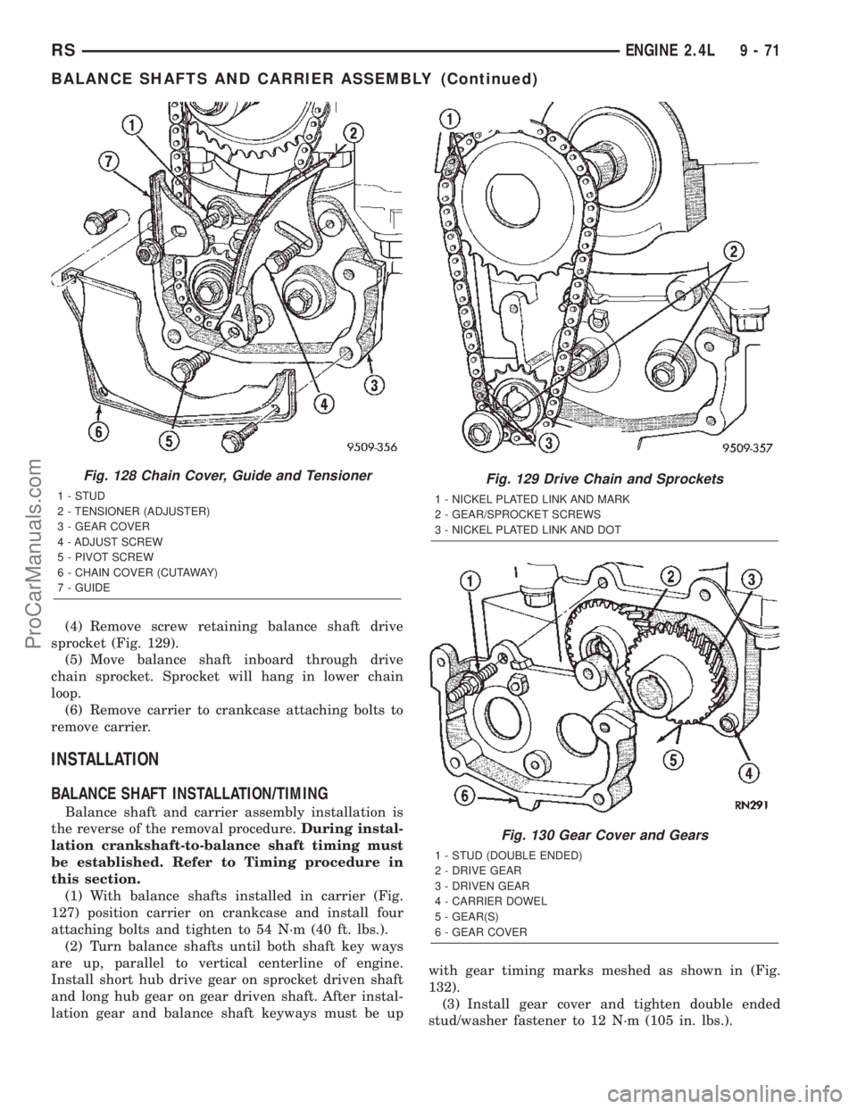
(4) Remove screw retaining balance shaft drive
sprocket (Fig. 129).
(5) Move balance shaft inboard through drive
chain sprocket. Sprocket will hang in lower chain
loop.
(6) Remove carrier to crankcase attaching bolts to
remove carrier.
INSTALLATION
BALANCE SHAFT INSTALLATION/TIMING
Balance shaft and carrier assembly installation is
the reverse of the removal procedure.During instal-
lation crankshaft-to-balance shaft timing must
be established. Refer to Timing procedure in
this section.
(1) With balance shafts installed in carrier (Fig.
127) position carrier on crankcase and install four
attaching bolts and tighten to 54 N´m (40 ft. lbs.).
(2) Turn balance shafts until both shaft key ways
are up, parallel to vertical centerline of engine.
Install short hub drive gear on sprocket driven shaft
and long hub gear on gear driven shaft. After instal-
lation gear and balance shaft keyways must be upwith gear timing marks meshed as shown in (Fig.
132).
(3) Install gear cover and tighten double ended
stud/washer fastener to 12 N´m (105 in. lbs.).
Fig. 128 Chain Cover, Guide and Tensioner
1 - STUD
2 - TENSIONER (ADJUSTER)
3 - GEAR COVER
4 - ADJUST SCREW
5 - PIVOT SCREW
6 - CHAIN COVER (CUTAWAY)
7 - GUIDE
Fig. 129 Drive Chain and Sprockets
1 - NICKEL PLATED LINK AND MARK
2 - GEAR/SPROCKET SCREWS
3 - NICKEL PLATED LINK AND DOT
Fig. 130 Gear Cover and Gears
1 - STUD (DOUBLE ENDED)
2 - DRIVE GEAR
3 - DRIVEN GEAR
4 - CARRIER DOWEL
5 - GEAR(S)
6 - GEAR COVER
RSENGINE 2.4L9-71
BALANCE SHAFTS AND CARRIER ASSEMBLY (Continued)
ProCarManuals.com
Page 1273 of 2399
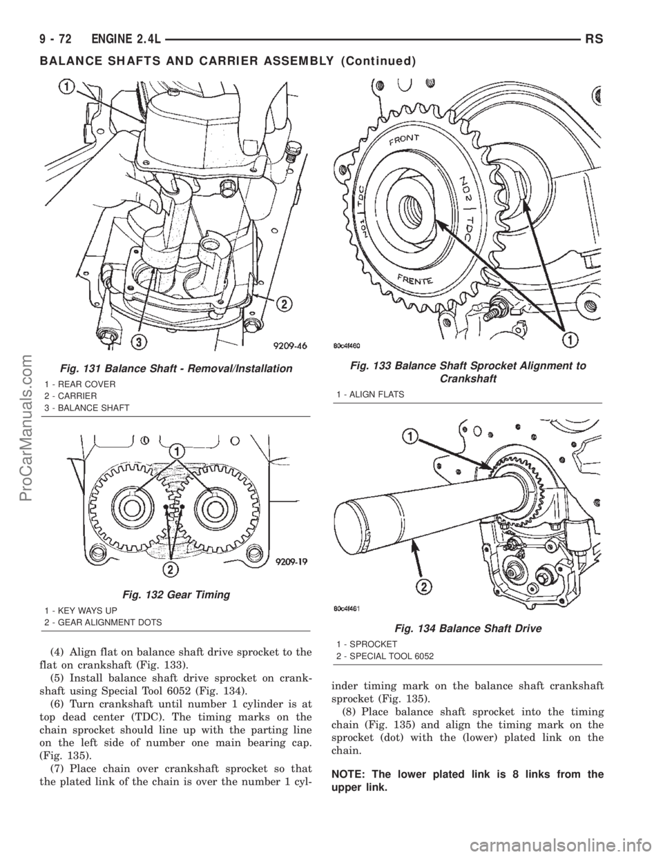
(4) Align flat on balance shaft drive sprocket to the
flat on crankshaft (Fig. 133).
(5) Install balance shaft drive sprocket on crank-
shaft using Special Tool 6052 (Fig. 134).
(6) Turn crankshaft until number 1 cylinder is at
top dead center (TDC). The timing marks on the
chain sprocket should line up with the parting line
on the left side of number one main bearing cap.
(Fig. 135).
(7) Place chain over crankshaft sprocket so that
the plated link of the chain is over the number 1 cyl-inder timing mark on the balance shaft crankshaft
sprocket (Fig. 135).
(8) Place balance shaft sprocket into the timing
chain (Fig. 135) and align the timing mark on the
sprocket (dot) with the (lower) plated link on the
chain.
NOTE: The lower plated link is 8 links from the
upper link.
Fig. 131 Balance Shaft - Removal/Installation
1 - REAR COVER
2 - CARRIER
3 - BALANCE SHAFT
Fig. 132 Gear Timing
1 - KEY WAYS UP
2 - GEAR ALIGNMENT DOTS
Fig. 133 Balance Shaft Sprocket Alignment to
Crankshaft
1 - ALIGN FLATS
Fig. 134 Balance Shaft Drive
1 - SPROCKET
2 - SPECIAL TOOL 6052
9 - 72 ENGINE 2.4LRS
BALANCE SHAFTS AND CARRIER ASSEMBLY (Continued)
ProCarManuals.com
Page 1274 of 2399
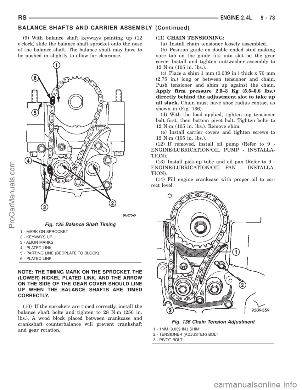
(9) With balance shaft keyways pointing up (12
o'clock) slide the balance shaft sprocket onto the nose
of the balance shaft. The balance shaft may have to
be pushed in slightly to allow for clearance.
NOTE: THE TIMING MARK ON THE SPROCKET, THE
(LOWER) NICKEL PLATED LINK, AND THE ARROW
ON THE SIDE OF THE GEAR COVER SHOULD LINE
UP WHEN THE BALANCE SHAFTS ARE TIMED
CORRECTLY.
(10) If the sprockets are timed correctly, install the
balance shaft bolts and tighten to 28 N´m (250 in.
lbs.). A wood block placed between crankcase and
crankshaft counterbalance will prevent crankshaft
and gear rotation.(11)CHAIN TENSIONING:
(a) Install chain tensioner loosely assembled.
(b) Position guide on double ended stud making
sure tab on the guide fits into slot on the gear
cover. Install and tighten nut/washer assembly to
12 N´m (105 in. lbs.).
(c) Place a shim 1 mm (0.039 in.) thick x 70 mm
(2.75 in.) long or between tensioner and chain.
Push tensioner and shim up against the chain.
Apply firm pressure 2.5±3 Kg (5.5±6.6 lbs.)
directly behind the adjustment slot to take up
all slack.Chain must have shoe radius contact as
shown in (Fig. 136).
(d) With the load applied, tighten top tensioner
bolt first, then bottom pivot bolt. Tighten bolts to
12 N´m (105 in. lbs.). Remove shim.
(e) Install carrier covers and tighten screws to
12 N´m (105 in. lbs.).
(12) If removed, install oil pump (Refer to 9 -
ENGINE/LUBRICATION/OIL PUMP - INSTALLA-
TION).
(13) Install pick-up tube and oil pan (Refer to 9 -
ENGINE/LUBRICATION/OIL PAN - INSTALLA-
TION).
(14) Fill engine crankcase with proper oil to cor-
rect level.
Fig. 135 Balance Shaft Timing
1 - MARK ON SPROCKET
2 - KEYWAYS UP
3 - ALIGN MARKS
4 - PLATED LINK
5 - PARTING LINE (BEDPLATE TO BLOCK)
6 - PLATED LINK
Fig. 136 Chain Tension Adjustment
1 - 1MM (0.039 IN.) SHIM
2 - TENSIONER (ADJUSTER) BOLT
3 - PIVOT BOLT
RSENGINE 2.4L9-73
BALANCE SHAFTS AND CARRIER ASSEMBLY (Continued)
ProCarManuals.com
Page 1277 of 2399
OIL PUMP
DESCRIPTION........................143
REMOVAL............................143
DISASSEMBLY........................144
CLEANING...........................144
INSPECTION.........................144
ASSEMBLY...........................146
INSTALLATION........................146
INTAKE MANIFOLD
DESCRIPTION........................146
OPERATION..........................146
DIAGNOSIS AND TESTING - INTAKE
MANIFOLD LEAKS....................146
INTAKE MANIFOLD - UPPER
STANDARD PROCEDURE
STANDARD PROCEDURE - MANIFOLD
STRIPPED THREAD REPAIR............146
STANDARD PROCEDURE - INTAKE
MANIFOLD VACUUM PORT REPAIR......147
REMOVAL - UPPER INTAKE MANIFOLD.....147
CLEANING...........................148
INSPECTION.........................149
INSTALLATION - UPPER INTAKE
MANIFOLD..........................149
INTAKE MANIFOLD - LOWER
REMOVAL - LOWER INTAKE MANIFOLD....150
CLEANING...........................150
INSPECTION.........................150
INSTALLATION - LOWER INTAKE MANIFOLD . 150
EXHAUST MANIFOLD
DESCRIPTION........................152OPERATION..........................152
EXHAUST MANIFOLD - RIGHT
REMOVAL............................152
CLEANING...........................152
INSPECTION.........................153
INSTALLATION........................153
EXHAUST MANIFOLD - LEFT
REMOVAL............................154
CLEANING...........................154
INSPECTION.........................154
INSTALLATION........................154
VALVE TIMING
STANDARD PROCEDURE
STANDARD PROCEDURE - VALVE TIMING
VERIFICATION.......................155
STANDARD PROCEDURE - MEASURING
TIMING CHAIN WEAR.................155
TIMING CHAIN COVER
REMOVAL............................155
INSTALLATION........................156
TIMING CHAIN AND SPROCKETS
REMOVAL
REMOVAL - TIMING CHAIN AND
CAMSHAFT SPROCKET...............159
REMOVAL - CRANKSHAFT SPROCKET . . . 159
INSTALLATION
INSTALLATION - CRANKSHAFT
SPROCKET.........................159
INSTALLATION - TIMING CHAIN AND
CAMSHAFT SPROCKET...............159
ENGINE 3.3/3.8L
DESCRIPTION
The 3.3 Liter (201 cu. in.) and 3.8 Liter (231 cu.
in.) engines are 60É V-6 engines with cast iron cylin-
der blocks and aluminum cylinder heads (Fig. 1). The
engine uses a single, block mounted camshaft with
pushrods to actuate the valves. These engines do not
have provisions for a free wheeling valve train.The firing order is 1±2±3±4±5±6. The cylinders are
numbered from the front of the engine to the rear.
The front cylinder bank is numbered 2, 4, and 6. The
rear cylinder bank is numbered 1, 3, and 5.
The engine identification number is located on the
rear of the cylinder block just below the cylinder
head (Fig. 2).
9 - 76 ENGINE 3.3/3.8LRS
ProCarManuals.com
Page 1279 of 2399
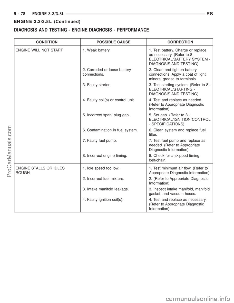
DIAGNOSIS AND TESTING - ENGINE DIAGNOSIS - PERFORMANCE
CONDITION POSSIBLE CAUSE CORRECTION
ENGINE WILL NOT START 1. Weak battery. 1. Test battery. Charge or replace
as necessary. (Refer to 8 -
ELECTRICAL/BATTERY SYSTEM -
DIAGNOSIS AND TESTING)
2. Corroded or loose battery
connections.2. Clean and tighten battery
connections. Apply a coat of light
mineral grease to terminals.
3. Faulty starter. 3. Test starting system. (Refer to 8 -
ELECTRICAL/STARTING -
DIAGNOSIS AND TESTING)
4. Faulty coil(s) or control unit. 4. Test and replace as needed.
(Refer to Appropriate Diagnostic
Information)
5. Incorrect spark plug gap. 5. Set gap. (Refer to 8 -
ELECTRICAL/IGNITION CONTROL
- SPECIFICATIONS)
6. Contamination in fuel system. 6. Clean system and replace fuel
filter.
7. Faulty fuel pump. 7. Test fuel pump and replace as
needed. (Refer to Appropriate
Diagnostic Information)
8. Incorrect engine timing. 8. Check for a skipped timing
belt/chain.
ENGINE STALLS OR IDLES
ROUGH1. Idle speed too low. 1. Test minimum air flow. (Refer to
Appropriate Diagnostic Information)
2. Incorrect fuel mixture. 2. (Refer to Appropriate Diagnostic
Information)
3. Intake manifold leakage. 3. Inspect intake manifold, manifold
gasket, and vacuum hoses.
4. Faulty ignition coil(s). 4. Test and replace as necessary.
(Refer to Appropriate Diagnostic
Information)
9 - 78 ENGINE 3.3/3.8LRS
ENGINE 3.3/3.8L (Continued)
ProCarManuals.com
Page 1297 of 2399
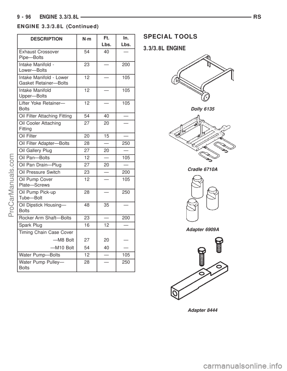
DESCRIPTION N´mFt.
Lbs.In.
Lbs.
Exhaust Crossover
PipeÐBolts54 40 Ð
Intake Manifold -
LowerÐBolts23 Ð 200
Intake Manifold - Lower
Gasket RetainerÐBolts12 Ð 105
Intake Manifold
UpperÐBolts12 Ð 105
Lifter Yoke RetainerÐ
Bolts12 Ð 105
Oil Filter Attaching Fitting 54 40 Ð
Oil Cooler Attaching
Fitting27 20 Ð
Oil Filter 20 15 Ð
Oil Filter AdapterÐBolts 28 Ð 250
Oil Gallery Plug 27 20 Ð
Oil PanÐBolts 12 Ð 105
Oil Pan DrainÐPlug 27 20 Ð
Oil Pressure Switch 23 Ð 200
Oil Pump Cover
PlateÐScrews12 Ð 105
Oil Pump Pick-up
TubeÐBolt28 Ð 250
Oil Dipstick HousingÐ
Bolts48 35 Ð
Rocker Arm ShaftÐBolts 23 Ð 200
Spark Plug 16 12 Ð
Timing Chain Case Cover
ÐM8 Bolt 27 20 Ð
ÐM10 Bolt 54 40 Ð
Water PumpÐBolts 12 Ð 105
Water Pump PulleyÐ
Bolts28 Ð 250SPECIAL TOOLS
3.3/3.8L ENGINE
Dolly 6135
Cradle 6710A
Adapter 6909A
Adapter 8444
9 - 96 ENGINE 3.3/3.8LRS
ENGINE 3.3/3.8L (Continued)
ProCarManuals.com
Page 1315 of 2399
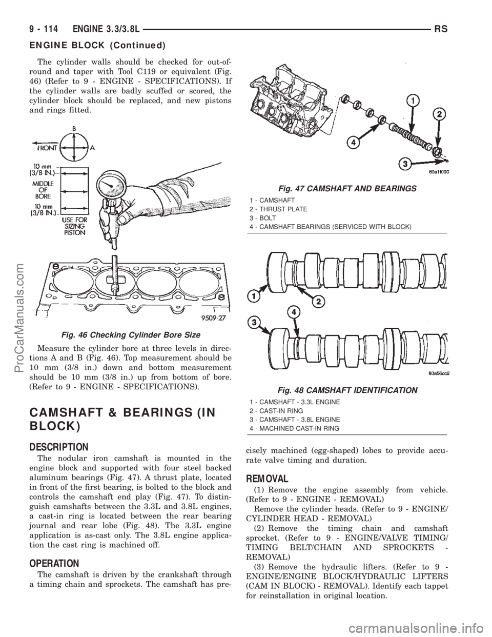
The cylinder walls should be checked for out-of-
round and taper with Tool C119 or equivalent (Fig.
46) (Refer to 9 - ENGINE - SPECIFICATIONS). If
the cylinder walls are badly scuffed or scored, the
cylinder block should be replaced, and new pistons
and rings fitted.
Measure the cylinder bore at three levels in direc-
tions A and B (Fig. 46). Top measurement should be
10 mm (3/8 in.) down and bottom measurement
should be 10 mm (3/8 in.) up from bottom of bore.
(Refer to 9 - ENGINE - SPECIFICATIONS).
CAMSHAFT & BEARINGS (IN
BLOCK)
DESCRIPTION
The nodular iron camshaft is mounted in the
engine block and supported with four steel backed
aluminum bearings (Fig. 47). A thrust plate, located
in front of the first bearing, is bolted to the block and
controls the camshaft end play (Fig. 47). To distin-
guish camshafts between the 3.3L and 3.8L engines,
a cast-in ring is located between the rear bearing
journal and rear lobe (Fig. 48). The 3.3L engine
application is as-cast only. The 3.8L engine applica-
tion the cast ring is machined off.
OPERATION
The camshaft is driven by the crankshaft through
a timing chain and sprockets. The camshaft has pre-cisely machined (egg-shaped) lobes to provide accu-
rate valve timing and duration.
REMOVAL
(1) Remove the engine assembly from vehicle.
(Refer to 9 - ENGINE - REMOVAL)
Remove the cylinder heads. (Refer to 9 - ENGINE/
CYLINDER HEAD - REMOVAL)
(2) Remove the timing chain and camshaft
sprocket. (Refer to 9 - ENGINE/VALVE TIMING/
TIMING BELT/CHAIN AND SPROCKETS -
REMOVAL)
(3) Remove the hydraulic lifters. (Refer to 9 -
ENGINE/ENGINE BLOCK/HYDRAULIC LIFTERS
(CAM IN BLOCK) - REMOVAL). Identify each tappet
for reinstallation in original location.
Fig. 46 Checking Cylinder Bore Size
Fig. 47 CAMSHAFT AND BEARINGS
1 - CAMSHAFT
2 - THRUST PLATE
3 - BOLT
4 - CAMSHAFT BEARINGS (SERVICED WITH BLOCK)
Fig. 48 CAMSHAFT IDENTIFICATION
1 - CAMSHAFT - 3.3L ENGINE
2 - CAST-IN RING
3 - CAMSHAFT - 3.8L ENGINE
4 - MACHINED CAST-IN RING
9 - 114 ENGINE 3.3/3.8LRS
ENGINE BLOCK (Continued)
ProCarManuals.com
Page 1316 of 2399
(4) Remove camshaft thrust plate (Fig. 47).
(5) Install a long bolt into front of camshaft to
facilitate removal of the camshaft.
(6) Remove the camshaft (Fig. 47), being careful
not to damage cam bearings with the cam lobes.
NOTE: The camshaft bearings are serviced with the
engine block.
INSPECTION
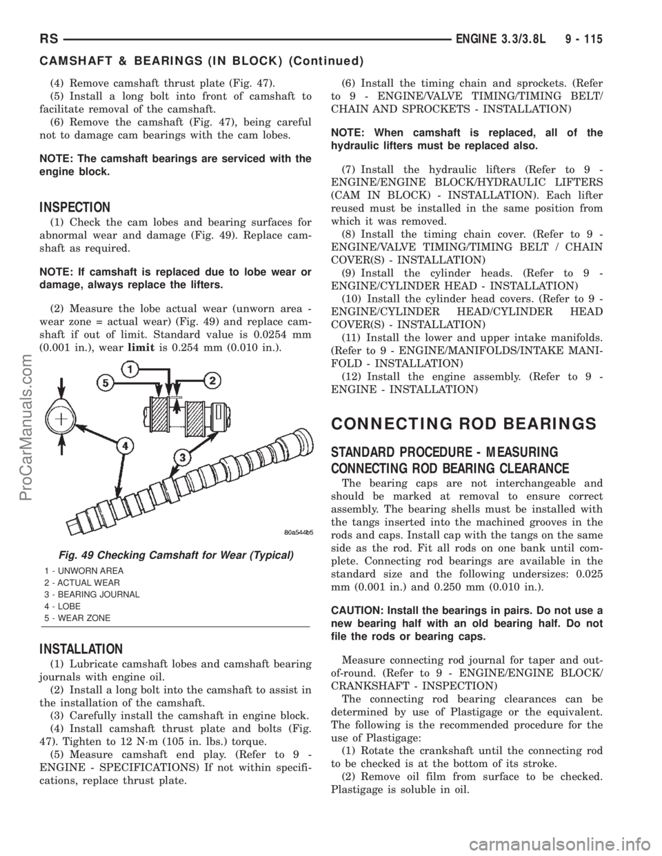
(1) Check the cam lobes and bearing surfaces for
abnormal wear and damage (Fig. 49). Replace cam-
shaft as required.
NOTE: If camshaft is replaced due to lobe wear or
damage, always replace the lifters.
(2) Measure the lobe actual wear (unworn area -
wear zone = actual wear) (Fig. 49) and replace cam-
shaft if out of limit. Standard value is 0.0254 mm
(0.001 in.), wearlimitis 0.254 mm (0.010 in.).
INSTALLATION
(1) Lubricate camshaft lobes and camshaft bearing
journals with engine oil.
(2) Install a long bolt into the camshaft to assist in
the installation of the camshaft.
(3) Carefully install the camshaft in engine block.
(4) Install camshaft thrust plate and bolts (Fig.
47). Tighten to 12 N´m (105 in. lbs.) torque.
(5) Measure camshaft end play. (Refer to 9 -
ENGINE - SPECIFICATIONS) If not within specifi-
cations, replace thrust plate.(6) Install the timing chain and sprockets. (Refer
to 9 - ENGINE/VALVE TIMING/TIMING BELT/
CHAIN AND SPROCKETS - INSTALLATION)
NOTE: When camshaft is replaced, all of the
hydraulic lifters must be replaced also.
(7) Install the hydraulic lifters (Refer to 9 -
ENGINE/ENGINE BLOCK/HYDRAULIC LIFTERS
(CAM IN BLOCK) - INSTALLATION). Each lifter
reused must be installed in the same position from
which it was removed.
(8) Install the timing chain cover. (Refer to 9 -
ENGINE/VALVE TIMING/TIMING BELT / CHAIN
COVER(S) - INSTALLATION)
(9) Install the cylinder heads. (Refer to 9 -
ENGINE/CYLINDER HEAD - INSTALLATION)
(10) Install the cylinder head covers. (Refer to 9 -
ENGINE/CYLINDER HEAD/CYLINDER HEAD
COVER(S) - INSTALLATION)
(11) Install the lower and upper intake manifolds.
(Refer to 9 - ENGINE/MANIFOLDS/INTAKE MANI-
FOLD - INSTALLATION)
(12) Install the engine assembly. (Refer to 9 -
ENGINE - INSTALLATION)
CONNECTING ROD BEARINGS
STANDARD PROCEDURE - MEASURING
CONNECTING ROD BEARING CLEARANCE
The bearing caps are not interchangeable and
should be marked at removal to ensure correct
assembly. The bearing shells must be installed with
the tangs inserted into the machined grooves in the
rods and caps. Install cap with the tangs on the same
side as the rod. Fit all rods on one bank until com-
plete. Connecting rod bearings are available in the
standard size and the following undersizes: 0.025
mm (0.001 in.) and 0.250 mm (0.010 in.).
CAUTION: Install the bearings in pairs. Do not use a
new bearing half with an old bearing half. Do not
file the rods or bearing caps.
Measure connecting rod journal for taper and out-
of-round. (Refer to 9 - ENGINE/ENGINE BLOCK/
CRANKSHAFT - INSPECTION)
The connecting rod bearing clearances can be
determined by use of Plastigage or the equivalent.
The following is the recommended procedure for the
use of Plastigage:
(1) Rotate the crankshaft until the connecting rod
to be checked is at the bottom of its stroke.
(2) Remove oil film from surface to be checked.
Plastigage is soluble in oil.
Fig. 49 Checking Camshaft for Wear (Typical)
1 - UNWORN AREA
2 - ACTUAL WEAR
3 - BEARING JOURNAL
4 - LOBE
5 - WEAR ZONE
RSENGINE 3.3/3.8L9 - 115
CAMSHAFT & BEARINGS (IN BLOCK) (Continued)
ProCarManuals.com