2002 CHRYSLER TOWN AND COUNTRY Grounds
[x] Cancel search: GroundsPage 665 of 2399

DESCRIPTION - CIRCUIT FUNCTIONS
All circuits in the diagrams use an alpha/numeric
code to identify the wire and it's function. To identify
which circuit code applies to a system, refer to the
Circuit Identification Code Chart. This chart shows
the main circuits only and does not show the second-
ary codes that may apply to some models.
CIRCUIT IDENTIFICATION CODE CHART
CIRCUIT FUNCTION
A BATTERY FEED
B BRAKE CONTROLS
C CLIMATE CONTROLS
D DIAGNOSTIC CIRCUITS
E DIMMING ILLUMINATION
CIRCUITS
F FUSED CIRCUITS
G MONITORING CIRCUITS
(GAUGES)
H OPEN
I NOT USED
J OPEN
K POWERTRAIN CONTROL
MODULE
L EXTERIOR LIGHTING
M INTERIOR LIGHTING
N NOT USED
O NOT USED
P POWER OPTION (BATTERY
FEED)
Q POWER OPTIONS (IGNITION
FEED)
R PASSIVE RESTRAINT
S SUSPENSION/STEERING
T TRANSMISSION/TRANSAXLE/
TRANSFER CASE
U OPEN
V SPEED CONTROL, WIPER/
WASHER
W OPEN
X AUDIO SYSTEMS
Y OPEN
Z GROUNDS
DESCRIPTION - SECTION IDENTIFICATION AND
INFORMATION
The wiring diagrams are grouped into individual
sections. If a component is most likely found in a par-
ticular group, it will be shown complete (all wires,
connectors, and pins) within that group. For exam-
ple, the Auto Shutdown Relay is most likely to be
found in Group 30, so it is shown there complete. It
can, however, be shown partially in another group if
it contains some associated wiring.
Splice diagrams in Section 8W-70 show the entire
splice and provide references to other sections the
splices serves. Section 8W-70 only contains splice dia-
grams that are not shown in their entirety some-
where else in the wiring diagrams.
Section 8W-80 shows each connector and the cir-
cuits involved with that connector. The connectors
are identified using the name/number on the dia-
gram pages.
WIRING SECTION CHART
GROUP TOPIC
8W-01 thru
8W-09General information and Diagram
Overview
8W-10 thru
8W-19Main Sources of Power and
Vehicle Grounding
8W-20 thru
8W-29Starting and Charging
8W-30 thru
8W-39Powertrain/Drivetrain Systems
8W-40 thru
8W-49Body Electrical items and A/C
8W-50 thru
8W-59Exterior Lighting, Wipers and
Trailer Tow
8W-60 thru
8W-69Power Accessories
8W-70 Splice Information
8W-80 Connector Pin Outs
8W-91 Connector, Ground and Splice
Locations
8W - 01 - 6 8W-01 WIRING DIAGRAM INFORMATIONRS
WIRING DIAGRAM INFORMATION (Continued)
ProCarManuals.com
Page 666 of 2399

DESCRIPTION - CONNECTOR, GROUND AND
SPLICE INFORMATION
CAUTION: Not all connectors are serviced. Some
connectors are serviced only with a harness. A typ-
ical example might be the Supplemental Restraint
System connectors. Always check parts availability
before attempting a repair.
IDENTIFICATION
In-line connectors are identified by a number, as
follows:
²In-line connectors located in the engine compart-
ment are C100 series numbers
²In-line connectors located in the Instrument
Panel area are C200 series numbers.
²In-line connectors located in the body are C300
series numbers.
²Jumper harness connectors are C400 series
numbers.
²Grounds and ground connectors are identified
with a ªGº and follow the same series numbering as
the in-line connectors.
²Splices are identified with an ªSº and follow the
same series numbering as the in-line connectors.
²Component connectors are identified by the com-
ponent name instead of a number. Multiple connec-
tors on a component use a C1, C2, etc. identifier.
LOCATIONS
Section 8W-91 contains connector/ground/splice
location illustrations. The illustrations contain the
connector name (or number)/ground number/splice
number and component identification. Connector/
ground/splice location charts in section 8W-91 refer-
ence the figure numbers of the illustrations.
The abbreviation T/O is used in the component
location section to indicate a point in which the wir-
ing harness branches out to a component. The abbre-
viation N/S means Not Shown in the illustrations
WARNING
WARNINGS - GENERAL
WARNINGSprovide information to prevent per-
sonal injury and vehicle damage. Below is a list of
general warnings that should be followed any time a
vehicle is being serviced.
WARNING: ALWAYS WEAR SAFETY GLASSES FOR
EYE PROTECTION.
WARNING: USE SAFETY STANDS ANYTIME A PRO-
CEDURE REQUIRES BEING UNDER A VEHICLE.WARNING: BE SURE THAT THE IGNITION SWITCH
ALWAYS IS IN THE OFF POSITION, UNLESS THE
PROCEDURE REQUIRES IT TO BE ON.
WARNING: SET THE PARKING BRAKE WHEN
WORKING ON ANY VEHICLE. AN AUTOMATIC
TRANSMISSION SHOULD BE IN PARK. A MANUAL
TRANSMISSION SHOULD BE IN NEUTRAL.
WARNING: OPERATE THE ENGINE ONLY IN A
WELL-VENTILATED AREA.
WARNING: KEEP AWAY FROM MOVING PARTS
WHEN THE ENGINE IS RUNNING, ESPECIALLY THE
FAN AND BELTS.
WARNING: TO PREVENT SERIOUS BURNS, AVOID
CONTACT WITH HOT PARTS SUCH AS THE RADIA-
TOR, EXHAUST MANIFOLD(S), TAIL PIPE, CATA-
LYTIC CONVERTER AND MUFFLER.
WARNING: DO NOT ALLOW FLAME OR SPARKS
NEAR THE BATTERY. GASES ARE ALWAYS
PRESENT IN AND AROUND THE BATTERY.
WARNING: ALWAYS REMOVE RINGS, WATCHES,
LOOSE HANGING JEWELRY AND AVOID LOOSE
CLOTHING.
DIAGNOSIS AND TESTING - WIRING HARNESS
TROUBLESHOOTING TOOLS
When diagnosing a problem in an electrical circuit
there are several common tools necessary. These tools
are listed and explained below.
²Jumper Wire - This is a test wire used to con-
nect two points of a circuit. It can be used to bypass
an open in a circuit.
WARNING: NEVER USE A JUMPER WIRE ACROSS
A LOAD, SUCH AS A MOTOR, CONNECTED
BETWEEN A BATTERY FEED AND GROUND.
²Voltmeter - Used to check for voltage on a cir-
cuit. Always connect the black lead to a known good
ground and the red lead to the positive side of the
circuit.
CAUTION: Most of the electrical components used
in today's vehicles are Solid State. When checking
voltages in these circuits, use a meter with a 10 -
megohm or greater impedance rating.
RS8W-01 WIRING DIAGRAM INFORMATION8W-01-7
WIRING DIAGRAM INFORMATION (Continued)
ProCarManuals.com
Page 676 of 2399

8W-02 COMPONENT INDEX
Component Page
A/C Compressor Clutch Relay............ 8W-42
A/C Compressor Clutch................. 8W-42
A/C- Heater Control.................... 8W-42
A/C Pressure Sensor................... 8W-42
A/C-Heater Control.................... 8W-42
Accelerator Pedal Position Sensor......... 8W-30
Accessory Relay....................... 8W-10
Adjustable Pedals Module............... 8W-30
Adjustable Pedals Switch................ 8W-30
Airbag Control Module.................. 8W-43
Ambient Temp Sensor.................. 8W-49
Antenna............................. 8W-47
Auto Shut Down Relay................. 8W-30
Auto Temp Control..................... 8W-42
Automatic Day/Night Mirror............. 8W-49
Back-Up Lamp Switch.................. 8W-51
Battery Temperature Sensor............. 8W-20
Battery............................. 8W-20
Blend Door Actuators................... 8W-42
Body Control Module................... 8W-45
Boost Pressure Sensor.................. 8W-30
B-Pillar Switches...................... 8W-61
Brake Lamp Switch................. 8W-30, 51
Brake Transmission Shift Interlock
Solenoid........................... 8W-31
Cabin Heater Assist.................... 8W-30
Camshaft Position Sensor............... 8W-30
CD Changer.......................... 8W-47
Center High Mounted Stop Lamp......... 8W-51
Cinch/Release Motors................... 8W-61
Clockspring.................. 8W-33, 41, 43, 47
Clutch Pedal Interlock Switch Jumper..... 8W-10
Clutch Pedal Interlock Switch............ 8W-10
Combination Relays.................... 8W-54
Controller Antilock Brake............... 8W-35
Crank Case Ventilation Heater........... 8W-30
Crankshaft Position Sensor.............. 8W-30
Cylinder Lock Switches................. 8W-39
Data Link Connector................... 8W-18
Diagnostic Junction Port................ 8W-18
Door Ajar Switches.................... 8W-39
Door Lock Motor/Ajar Switches........... 8W-61
Door Lock Switches.................... 8W-61
Driver Airbag......................... 8W-43
EGR Solenoid......................... 8W-30
Electric Wiper De-Icer.................. 8W-48
Engine Control Module................. 8W-30
Engine Coolant Temp Sensor............. 8W-30
Engine Oil Pressure Switch.............. 8W-30
EVAP/Purge Solenoid................... 8W-30
Evaporator Temperature Sensor.......... 8W-42
Floor Console Lamp.................... 8W-44Component Page
Fog Lamps........................... 8W-50
Front Blower Module................... 8W-42
Front Blower Motor Relay............... 8W-42
Front Blower Motor.................... 8W-42
Front Cigar Lighter.................... 8W-41
Front Control Module.................. 8W-10
Front Fog Lamp Relay.................. 8W-50
Front Intrusion Sensor................. 8W-39
Front Washer Pump Motor.............. 8W-53
Front Wiper On/Off Relay............... 8W-53
Fuel Heater.......................... 8W-30
Fuel Injectors........................ 8W-30
Fuel Pressure Solenoid................. 8W-30
Fuel Pump Module.................... 8W-30
Full Open Switches.................... 8W-61
Fuselink............................. 8W-10
Fuses............................... 8W-10
Generator............................ 8W-20
Glow Plug Relay...................... 8W-30
Glow Plugs........................... 8W-30
Grounds............................. 8W-15
Halo Lamp........................... 8W-44
Headlamp Leveling Motors.............. 8W-50
Headlamp Switch...................... 8W-50
Headlamp Washer Relay................ 8W-53
Headlamps........................... 8W-50
Heated Seat Backs..................... 8W-63
Heated Seat Cushions.................. 8W-63
Heated Seat Modules................... 8W-63
High Beam Lamps..................... 8W-50
High Note Horn....................... 8W-41
Horn Relay.......................... 8W-41
Idle Air Control Motor.................. 8W-30
Ignition Coil.......................... 8W-30
Ignition Switch....................... 8W-10
Inlet Air Temperature Sensor............ 8W-30
Instrument Cluster.................... 8W-40
Instrument Panel Switch Bank . . 8W-44, 52, 53, 63
Integrated Power Module................ 8W-10
Knock Sensor......................... 8W-30
License Lamp......................... 8W-51
Lift Pump Motor...................... 8W-30
Liftgate Ajar Switch................. 8W-39, 61
Liftgate Cinch/Release Motor............. 8W-61
Liftgate Cylinder Lock Switch............ 8W-39
Liftgate Flood Lamps................... 8W-44
Liftgate Right Pinch Sensor.............. 8W-61
Low Beam Lamps.................... 8W-50-9
Manifold Absolute Pressure Sensor........ 8W-30
Mass Air Flow Sensor.................. 8W-30
Memory Seat/Mirror Module.......... 8W-62, 63
Memory Set Switch.................... 8W-63
RS8W-02 COMPONENT INDEX8W-02-1
ProCarManuals.com
Page 1158 of 2399
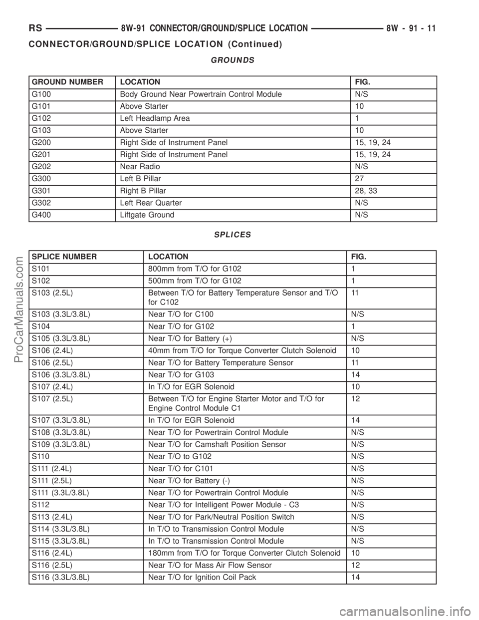
GROUNDS
GROUND NUMBER LOCATION FIG.
G100 Body Ground Near Powertrain Control Module N/S
G101 Above Starter 10
G102 Left Headlamp Area 1
G103 Above Starter 10
G200 Right Side of Instrument Panel 15, 19, 24
G201 Right Side of Instrument Panel 15, 19, 24
G202 Near Radio N/S
G300 Left B Pillar 27
G301 Right B Pillar 28, 33
G302 Left Rear Quarter N/S
G400 Liftgate Ground N/S
SPLICES
SPLICE NUMBER LOCATION FIG.
S101 800mm from T/O for G102 1
S102 500mm from T/O for G102 1
S103 (2.5L) Between T/O for Battery Temperature Sensor and T/O
for C10211
S103 (3.3L/3.8L) Near T/O for C100 N/S
S104 Near T/O for G102 1
S105 (3.3L/3.8L) Near T/O for Battery (+) N/S
S106 (2.4L) 40mm from T/O for Torque Converter Clutch Solenoid 10
S106 (2.5L) Near T/O for Battery Temperature Sensor 11
S106 (3.3L/3.8L) Near T/O for G103 14
S107 (2.4L) In T/O for EGR Solenoid 10
S107 (2.5L) Between T/O for Engine Starter Motor and T/O for
Engine Control Module C112
S107 (3.3L/3.8L) In T/O for EGR Solenoid 14
S108 (3.3L/3.8L) Near T/O for Powertrain Control Module N/S
S109 (3.3L/3.8L) Near T/O for Camshaft Position Sensor N/S
S110 Near T/O to G102 N/S
S111 (2.4L) Near T/O for C101 N/S
S111 (2.5L) Near T/O for Battery (-) N/S
S111 (3.3L/3.8L) Near T/O for Powertrain Control Module N/S
S112 Near T/O for Intelligent Power Module - C3 N/S
S113 (2.4L) Near T/O for Park/Neutral Position Switch N/S
S114 (3.3L/3.8L) In T/O to Transmission Control Module N/S
S115 (3.3L/3.8L) In T/O to Transmission Control Module N/S
S116 (2.4L) 180mm from T/O for Torque Converter Clutch Solenoid 10
S116 (2.5L) Near T/O for Mass Air Flow Sensor 12
S116 (3.3L/3.8L) Near T/O for Ignition Coil Pack 14
RS8W-91 CONNECTOR/GROUND/SPLICE LOCATION8W-91-11
CONNECTOR/GROUND/SPLICE LOCATION (Continued)
ProCarManuals.com
Page 1518 of 2399
IGNITION SWITCH
REMOVAL
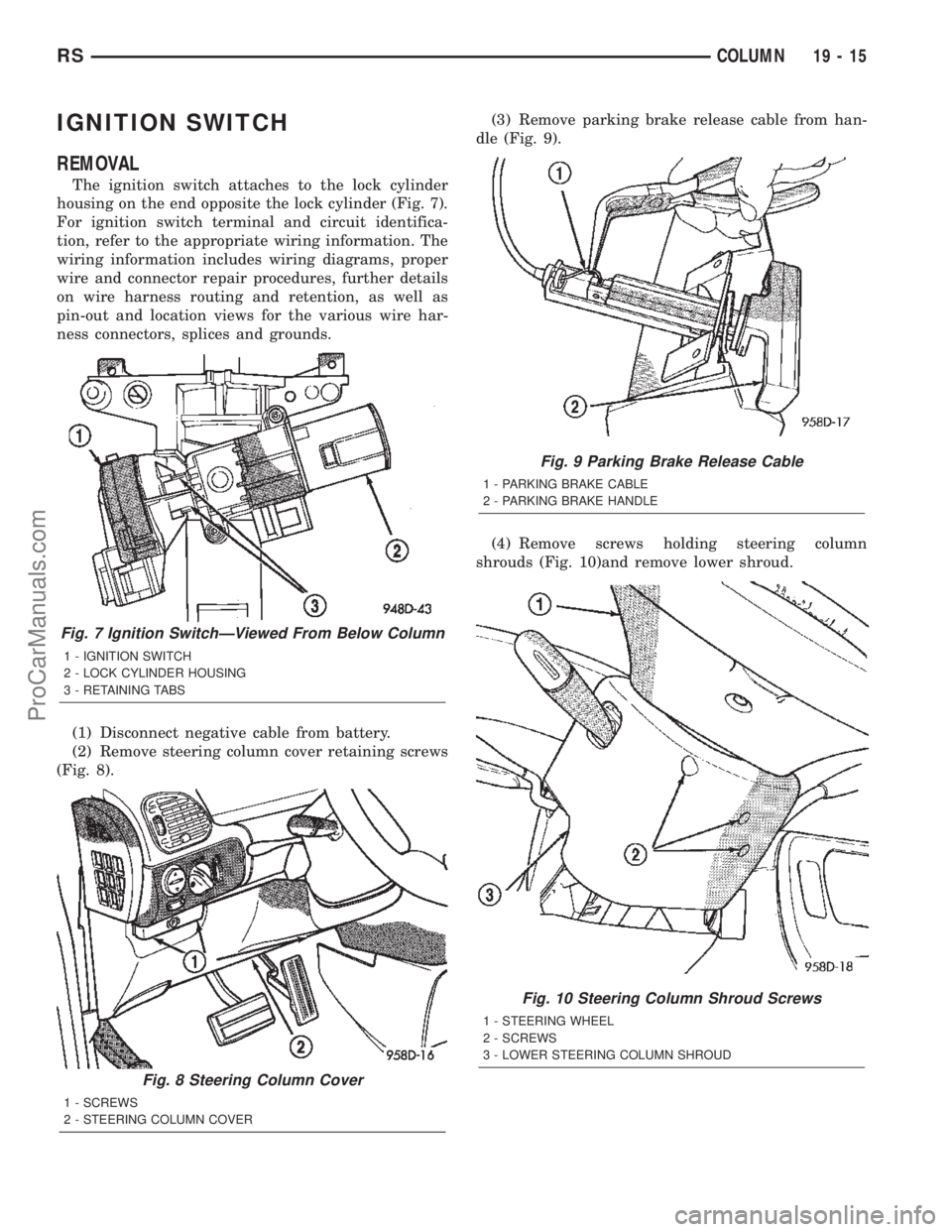
The ignition switch attaches to the lock cylinder
housing on the end opposite the lock cylinder (Fig. 7).
For ignition switch terminal and circuit identifica-
tion, refer to the appropriate wiring information. The
wiring information includes wiring diagrams, proper
wire and connector repair procedures, further details
on wire harness routing and retention, as well as
pin-out and location views for the various wire har-
ness connectors, splices and grounds.
(1) Disconnect negative cable from battery.
(2) Remove steering column cover retaining screws
(Fig. 8).(3) Remove parking brake release cable from han-
dle (Fig. 9).
(4) Remove screws holding steering column
shrouds (Fig. 10)and remove lower shroud.
Fig. 7 Ignition SwitchÐViewed From Below Column
1 - IGNITION SWITCH
2 - LOCK CYLINDER HOUSING
3 - RETAINING TABS
Fig. 8 Steering Column Cover
1 - SCREWS
2 - STEERING COLUMN COVER
Fig. 9 Parking Brake Release Cable
1 - PARKING BRAKE CABLE
2 - PARKING BRAKE HANDLE
Fig. 10 Steering Column Shroud Screws
1 - STEERING WHEEL
2 - SCREWS
3 - LOWER STEERING COLUMN SHROUD
RSCOLUMN19-15
ProCarManuals.com
Page 1587 of 2399
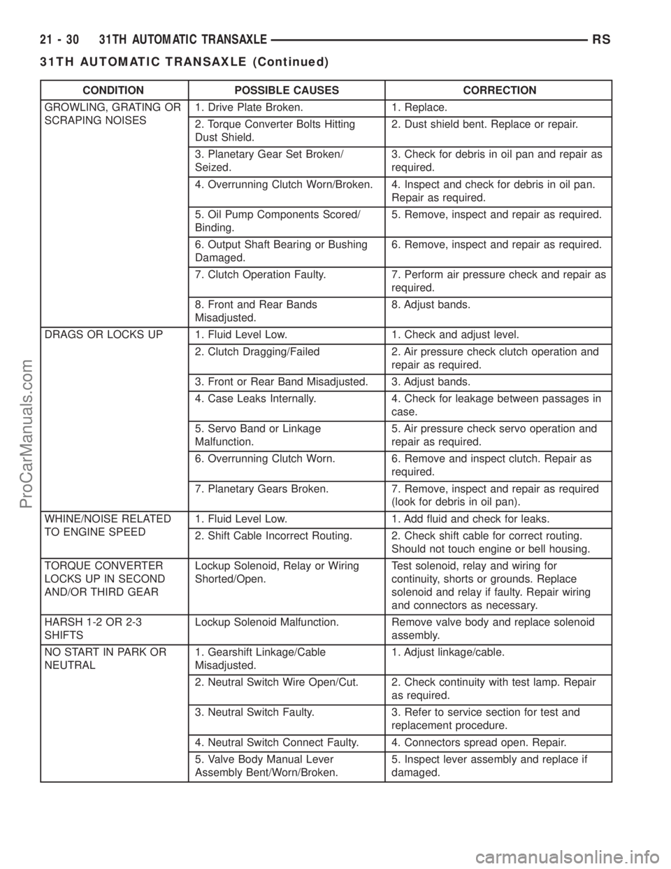
CONDITION POSSIBLE CAUSES CORRECTION
GROWLING, GRATING OR
SCRAPING NOISES1. Drive Plate Broken. 1. Replace.
2. Torque Converter Bolts Hitting
Dust Shield.2. Dust shield bent. Replace or repair.
3. Planetary Gear Set Broken/
Seized.3. Check for debris in oil pan and repair as
required.
4. Overrunning Clutch Worn/Broken. 4. Inspect and check for debris in oil pan.
Repair as required.
5. Oil Pump Components Scored/
Binding.5. Remove, inspect and repair as required.
6. Output Shaft Bearing or Bushing
Damaged.6. Remove, inspect and repair as required.
7. Clutch Operation Faulty. 7. Perform air pressure check and repair as
required.
8. Front and Rear Bands
Misadjusted.8. Adjust bands.
DRAGS OR LOCKS UP 1. Fluid Level Low. 1. Check and adjust level.
2. Clutch Dragging/Failed 2. Air pressure check clutch operation and
repair as required.
3. Front or Rear Band Misadjusted. 3. Adjust bands.
4. Case Leaks Internally. 4. Check for leakage between passages in
case.
5. Servo Band or Linkage
Malfunction.5. Air pressure check servo operation and
repair as required.
6. Overrunning Clutch Worn. 6. Remove and inspect clutch. Repair as
required.
7. Planetary Gears Broken. 7. Remove, inspect and repair as required
(look for debris in oil pan).
WHINE/NOISE RELATED
TO ENGINE SPEED1. Fluid Level Low. 1. Add fluid and check for leaks.
2. Shift Cable Incorrect Routing. 2. Check shift cable for correct routing.
Should not touch engine or bell housing.
TORQUE CONVERTER
LOCKS UP IN SECOND
AND/OR THIRD GEARLockup Solenoid, Relay or Wiring
Shorted/Open.Test solenoid, relay and wiring for
continuity, shorts or grounds. Replace
solenoid and relay if faulty. Repair wiring
and connectors as necessary.
HARSH 1-2 OR 2-3
SHIFTSLockup Solenoid Malfunction. Remove valve body and replace solenoid
assembly.
NO START IN PARK OR
NEUTRAL1. Gearshift Linkage/Cable
Misadjusted.1. Adjust linkage/cable.
2. Neutral Switch Wire Open/Cut. 2. Check continuity with test lamp. Repair
as required.
3. Neutral Switch Faulty. 3. Refer to service section for test and
replacement procedure.
4. Neutral Switch Connect Faulty. 4. Connectors spread open. Repair.
5. Valve Body Manual Lever
Assembly Bent/Worn/Broken.5. Inspect lever assembly and replace if
damaged.
21 - 30 31TH AUTOMATIC TRANSAXLERS
31TH AUTOMATIC TRANSAXLE (Continued)
ProCarManuals.com
Page 2257 of 2399
Refer to the appropriate wiring information. The
wiring information includes wiring diagrams, proper
wire and connector repair procedures, further details
on wire harness routing and retention, as well as
pin-out and location views for the various wire har-
ness connectors, splices, and grounds.
DIAGNOSIS AND TESTING - BLOWER MOTOR
RELAY
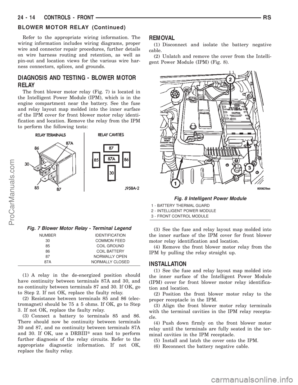
The front blower motor relay (Fig. 7) is located in
the Intelligent Power Module (IPM), which is in the
engine compartment near the battery. See the fuse
and relay layout map molded into the inner surface
of the IPM cover for front blower motor relay identi-
fication and location. Remove the relay from the IPM
to perform the following tests:
(1) A relay in the de-energized position should
have continuity between terminals 87A and 30, and
no continuity between terminals 87 and 30. If OK, go
to Step 2. If not OK, replace the faulty relay.
(2) Resistance between terminals 85 and 86 (elec-
tromagnet) should be 75 5 ohms. If OK, go to Step
3. If not OK, replace the faulty relay.
(3) Connect a battery to terminals 85 and 86.
There should now be continuity between terminals
30 and 87, and no continuity between terminals 87A
and 30. If OK, use a DRBIIItscan tool to perform
further diagnosis of the relay circuits. Refer to the
appropriate diagnostic information. If not OK,
replace the faulty relay.
REMOVAL
(1) Disconnect and isolate the battery negative
cable.
(2) Unlatch and remove the cover from the Intelli-
gent Power Module (IPM) (Fig. 8).
(3) See the fuse and relay layout map molded into
the inner surface of the IPM cover for front blower
motor relay identification and location.
(4) Remove the front blower motor relay from the
IPM by pulling the relay straight up.
INSTALLATION
(1) See the fuse and relay layout map molded into
the inner surface of the Intelligent Power Module
(IPM) cover for front blower motor relay identifica-
tion and location.
(2) Position the front blower motor relay to the
proper receptacle in the IPM.
(3) Align the front blower motor relay terminals
with the terminal cavities in the IPM relay recepta-
cle.
(4) Push down firmly on the front blower motor
relay until the terminals are fully seated in the ter-
minal cavities in the IPM receptacle.
(5) Install and latch the cover onto the IPM.
(6) Reconnect the battery negative cable.
Fig. 7 Blower Motor Relay - Terminal Legend
NUMBER IDENTIFICATION
30 COMMON FEED
85 COIL GROUND
86 COIL BATTERY
87 NORMALLY OPEN
87A NORMALLY CLOSED
Fig. 8 Intelligent Power Module
1 - BATTERY THERMAL GUARD
2 - INTELLIGENT POWER MODULE
3 - FRONT CONTROL MODULE
24 - 14 CONTROLS - FRONTRS
BLOWER MOTOR RELAY (Continued)
ProCarManuals.com
Page 2258 of 2399
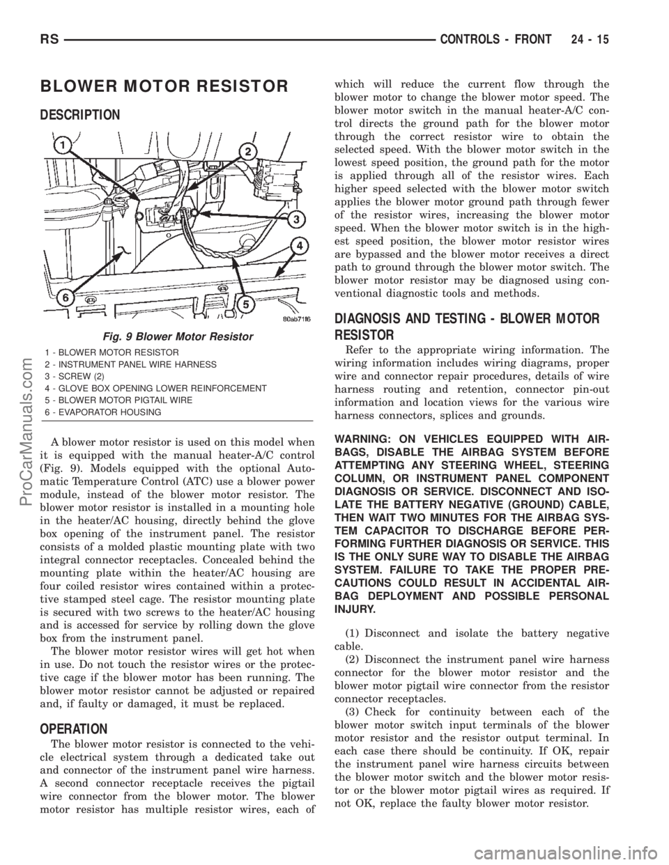
BLOWER MOTOR RESISTOR
DESCRIPTION
A blower motor resistor is used on this model when
it is equipped with the manual heater-A/C control
(Fig. 9). Models equipped with the optional Auto-
matic Temperature Control (ATC) use a blower power
module, instead of the blower motor resistor. The
blower motor resistor is installed in a mounting hole
in the heater/AC housing, directly behind the glove
box opening of the instrument panel. The resistor
consists of a molded plastic mounting plate with two
integral connector receptacles. Concealed behind the
mounting plate within the heater/AC housing are
four coiled resistor wires contained within a protec-
tive stamped steel cage. The resistor mounting plate
is secured with two screws to the heater/AC housing
and is accessed for service by rolling down the glove
box from the instrument panel.
The blower motor resistor wires will get hot when
in use. Do not touch the resistor wires or the protec-
tive cage if the blower motor has been running. The
blower motor resistor cannot be adjusted or repaired
and, if faulty or damaged, it must be replaced.
OPERATION
The blower motor resistor is connected to the vehi-
cle electrical system through a dedicated take out
and connector of the instrument panel wire harness.
A second connector receptacle receives the pigtail
wire connector from the blower motor. The blower
motor resistor has multiple resistor wires, each ofwhich will reduce the current flow through the
blower motor to change the blower motor speed. The
blower motor switch in the manual heater-A/C con-
trol directs the ground path for the blower motor
through the correct resistor wire to obtain the
selected speed. With the blower motor switch in the
lowest speed position, the ground path for the motor
is applied through all of the resistor wires. Each
higher speed selected with the blower motor switch
applies the blower motor ground path through fewer
of the resistor wires, increasing the blower motor
speed. When the blower motor switch is in the high-
est speed position, the blower motor resistor wires
are bypassed and the blower motor receives a direct
path to ground through the blower motor switch. The
blower motor resistor may be diagnosed using con-
ventional diagnostic tools and methods.
DIAGNOSIS AND TESTING - BLOWER MOTOR
RESISTOR
Refer to the appropriate wiring information. The
wiring information includes wiring diagrams, proper
wire and connector repair procedures, details of wire
harness routing and retention, connector pin-out
information and location views for the various wire
harness connectors, splices and grounds.
WARNING: ON VEHICLES EQUIPPED WITH AIR-
BAGS, DISABLE THE AIRBAG SYSTEM BEFORE
ATTEMPTING ANY STEERING WHEEL, STEERING
COLUMN, OR INSTRUMENT PANEL COMPONENT
DIAGNOSIS OR SERVICE. DISCONNECT AND ISO-
LATE THE BATTERY NEGATIVE (GROUND) CABLE,
THEN WAIT TWO MINUTES FOR THE AIRBAG SYS-
TEM CAPACITOR TO DISCHARGE BEFORE PER-
FORMING FURTHER DIAGNOSIS OR SERVICE. THIS
IS THE ONLY SURE WAY TO DISABLE THE AIRBAG
SYSTEM. FAILURE TO TAKE THE PROPER PRE-
CAUTIONS COULD RESULT IN ACCIDENTAL AIR-
BAG DEPLOYMENT AND POSSIBLE PERSONAL
INJURY.
(1) Disconnect and isolate the battery negative
cable.
(2) Disconnect the instrument panel wire harness
connector for the blower motor resistor and the
blower motor pigtail wire connector from the resistor
connector receptacles.
(3) Check for continuity between each of the
blower motor switch input terminals of the blower
motor resistor and the resistor output terminal. In
each case there should be continuity. If OK, repair
the instrument panel wire harness circuits between
the blower motor switch and the blower motor resis-
tor or the blower motor pigtail wires as required. If
not OK, replace the faulty blower motor resistor.
Fig. 9 Blower Motor Resistor
1 - BLOWER MOTOR RESISTOR
2 - INSTRUMENT PANEL WIRE HARNESS
3 - SCREW (2)
4 - GLOVE BOX OPENING LOWER REINFORCEMENT
5 - BLOWER MOTOR PIGTAIL WIRE
6 - EVAPORATOR HOUSING
RSCONTROLS - FRONT24-15
ProCarManuals.com