2002 CHRYSLER TOWN AND COUNTRY fuel cap
[x] Cancel search: fuel capPage 1460 of 2399
WARNING: THE FUEL RESERVOIR OF THE FUEL
PUMP MODULE DOES NOT EMPTY OUT WHEN THE
TANK IS DRAINED. THE FUEL IN THE RESERVOIR
MAY SPILL OUT WHEN THE MODULE IS REMOVED.
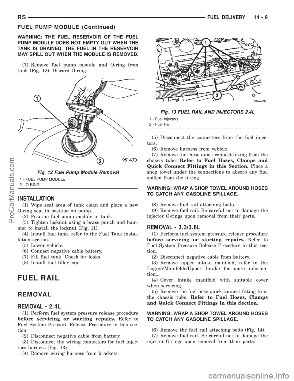
(7) Remove fuel pump module and O-ring from
tank (Fig. 12). Discard O-ring.
INSTALLATION
(1) Wipe seal area of tank clean and place a new
O-ring seal in position on pump.
(2) Position fuel pump module in tank.
(3) Tighten locknut using a brass punch and ham-
mer to install the locknut (Fig. 11).
(4) Install fuel tank, refer to the Fuel Tank instal-
lation section.
(5) Lower vehicle.
(6) Connect negative cable battery.
(7) Fill fuel tank. Check for leaks.
(8) Install fuel filler cap.
FUEL RAIL
REMOVAL
REMOVAL - 2.4L
(1) Perform fuel system pressure release procedure
before servicing or starting repairs.Refer to
Fuel System Pressure Release Procedure in this sec-
tion.
(2) Disconnect negative cable from battery.
(3) Disconnect the wiring connectors for fuel injec-
tors harness (Fig. 13).
(4) Remove wiring harness from brackets.(5) Disconnect the connectors from the fuel injec-
tors.
(6) Remove harness from vehicle.
(7) Remove fuel hose quick connect fitting from the
chassis tube.Refer to Fuel Hoses, Clamps and
Quick Connect Fittings in this Section.Place a
shop towel under the connections to absorb any fuel
spilled from the fitting.
WARNING: WRAP A SHOP TOWEL AROUND HOSES
TO CATCH ANY GASOLINE SPILLAGE.
(8) Remove fuel rail attaching bolts.
(9) Remove fuel rail. Be careful not to damage the
injector O-rings upon removal from their ports.
REMOVAL - 3.3/3.8L
(1) Perform fuel system pressure release procedure
before servicing or starting repairs.Refer to
Fuel System Pressure Release Procedure in this sec-
tion.
(2) Disconnect negative cable from battery.
(3) Remove upper intake manifold, refer to the
Engine/Manifolds/Upper Intake for more informa-
tion..
(4) Cover intake manifold with suitable cover
when servicing.
(5) Remove the fuel hose quick connect fitting from
the chassis tube.Refer to Fuel Hoses, Clamps
and Quick Connect Fittings in this Section.
WARNING: WRAP A SHOP TOWEL AROUND HOSES
TO CATCH ANY GASOLINE SPILLAGE.
(6) Remove the fuel rail attaching bolts (Fig. 14).
(7) Remove fuel rail. Be careful not to damage the
injector O-rings upon removal from their ports.
Fig. 12 Fuel Pump Module Removal
1 - FUEL PUMP MODULE
2 - O-RING
Fig. 13 FUEL RAIL AND INJECTORS 2.4L
1 - Fuel Injectors
2 - Fuel Rail
RSFUEL DELIVERY14-9
FUEL PUMP MODULE (Continued)
ProCarManuals.com
Page 1462 of 2399
REMOVAL
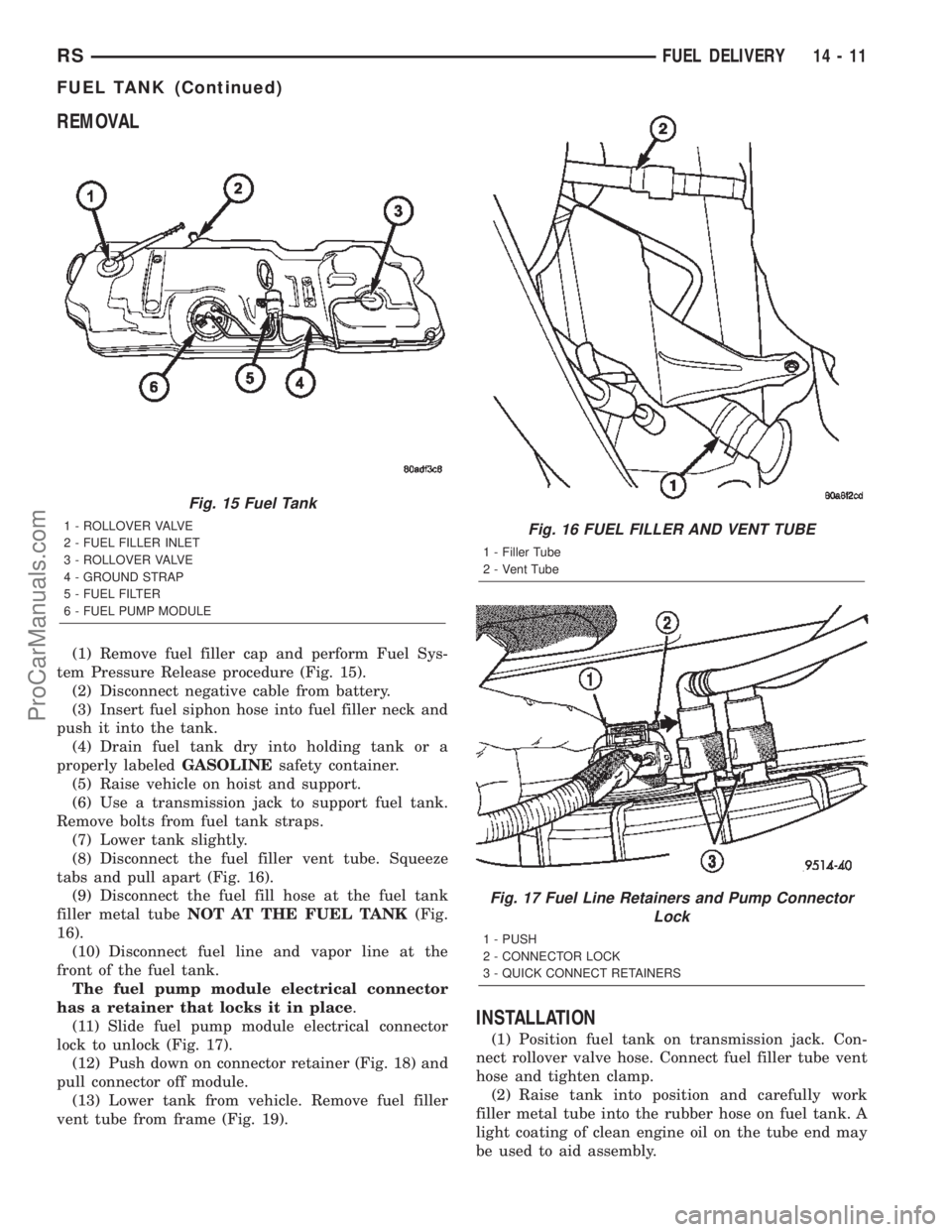
(1) Remove fuel filler cap and perform Fuel Sys-
tem Pressure Release procedure (Fig. 15).
(2) Disconnect negative cable from battery.
(3) Insert fuel siphon hose into fuel filler neck and
push it into the tank.
(4) Drain fuel tank dry into holding tank or a
properly labeledGASOLINEsafety container.
(5) Raise vehicle on hoist and support.
(6) Use a transmission jack to support fuel tank.
Remove bolts from fuel tank straps.
(7) Lower tank slightly.
(8) Disconnect the fuel filler vent tube. Squeeze
tabs and pull apart (Fig. 16).
(9) Disconnect the fuel fill hose at the fuel tank
filler metal tubeNOT AT THE FUEL TANK(Fig.
16).
(10) Disconnect fuel line and vapor line at the
front of the fuel tank.
The fuel pump module electrical connector
has a retainer that locks it in place.
(11) Slide fuel pump module electrical connector
lock to unlock (Fig. 17).
(12) Push down on connector retainer (Fig. 18) and
pull connector off module.
(13) Lower tank from vehicle. Remove fuel filler
vent tube from frame (Fig. 19).
INSTALLATION
(1) Position fuel tank on transmission jack. Con-
nect rollover valve hose. Connect fuel filler tube vent
hose and tighten clamp.
(2) Raise tank into position and carefully work
filler metal tube into the rubber hose on fuel tank. A
light coating of clean engine oil on the tube end may
be used to aid assembly.
Fig. 15 Fuel Tank
1 - ROLLOVER VALVE
2 - FUEL FILLER INLET
3 - ROLLOVER VALVE
4 - GROUND STRAP
5 - FUEL FILTER
6 - FUEL PUMP MODULEFig. 16 FUEL FILLER AND VENT TUBE
1 - Filler Tube
2 - Vent Tube
Fig. 17 Fuel Line Retainers and Pump Connector
Lock
1 - PUSH
2 - CONNECTOR LOCK
3 - QUICK CONNECT RETAINERS
RSFUEL DELIVERY14-11
FUEL TANK (Continued)
ProCarManuals.com
Page 1463 of 2399
(3) Feed filler vent line thru frame rail. Careful
not to cross lines.
(4) Tighten strap bolts to 54 N´m (40 ft. lbs.)
torque. Tighten T strap bolt to 28.2 N´m (250 in.
lbs.). Remove transmission jack.
(5) Tighten filler hose clamp to 3.3 N´m (30 in.
lbs.).
CAUTION: Ensure straps are not twisted or bent
before or after tightening strap nuts.
(6) Connect fuel pump/module electrical connector.
Place retainer in locked position.(7) Lubricate the fuel supply line with clean 30
weight engine oil, install the quick connect fuel fit-
ting. Refer to Tube/Fitting Assembly in the Fuel
Delivery section of this section.
(8) Attach filler vent line to filler tube. Pull on
connector to make sure of connection.
(9) Fill fuel tank, replace cap, and connect battery
negative cable.
(10) Use the DRBIIItscan tool to pressurize the
fuel system. Check for leaks.
FUEL TANK FILLER TUBE
REMOVAL
(1) Disconnect the negative battery cable.
(2) Remove the 3 screws at the filler door.
(3) Raise and support vehicle
(4) Remove the left rear tire.
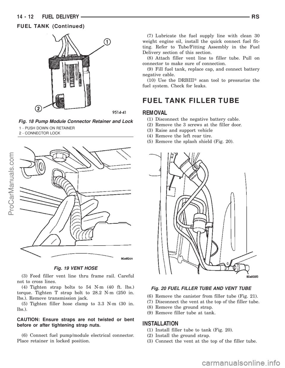
(5) Remove the splash shield (Fig. 20).
(6) Remove the canister from filler tube (Fig. 21).
(7) Disconnect the vent at the top of the filler tube.
(8) Remove the ground strap.
(9) Remove filler tube at tank.
INSTALLATION
(1) Install filler tube to tank (Fig. 20).
(2) Install the ground strap.
(3) Connect the vent at the top of the filler tube.
Fig. 18 Pump Module Connector Retainer and Lock
1 - PUSH DOWN ON RETAINER
2 - CONNECTOR LOCK
Fig. 19 VENT HOSE
Fig. 20 FUEL FILLER TUBE AND VENT TUBE
14 - 12 FUEL DELIVERYRS
FUEL TANK (Continued)
ProCarManuals.com
Page 1476 of 2399
OPERATION
The Transmission Control Module (TCM) supplies
the road speed and distance traveled inputs to the
PCM. From these inputs and the throttle position
sensor input, the PCM determines when a decelera-
tion condition occurs.
FUEL INJECTOR
DESCRIPTION
The injectors are positioned in the intake manifold
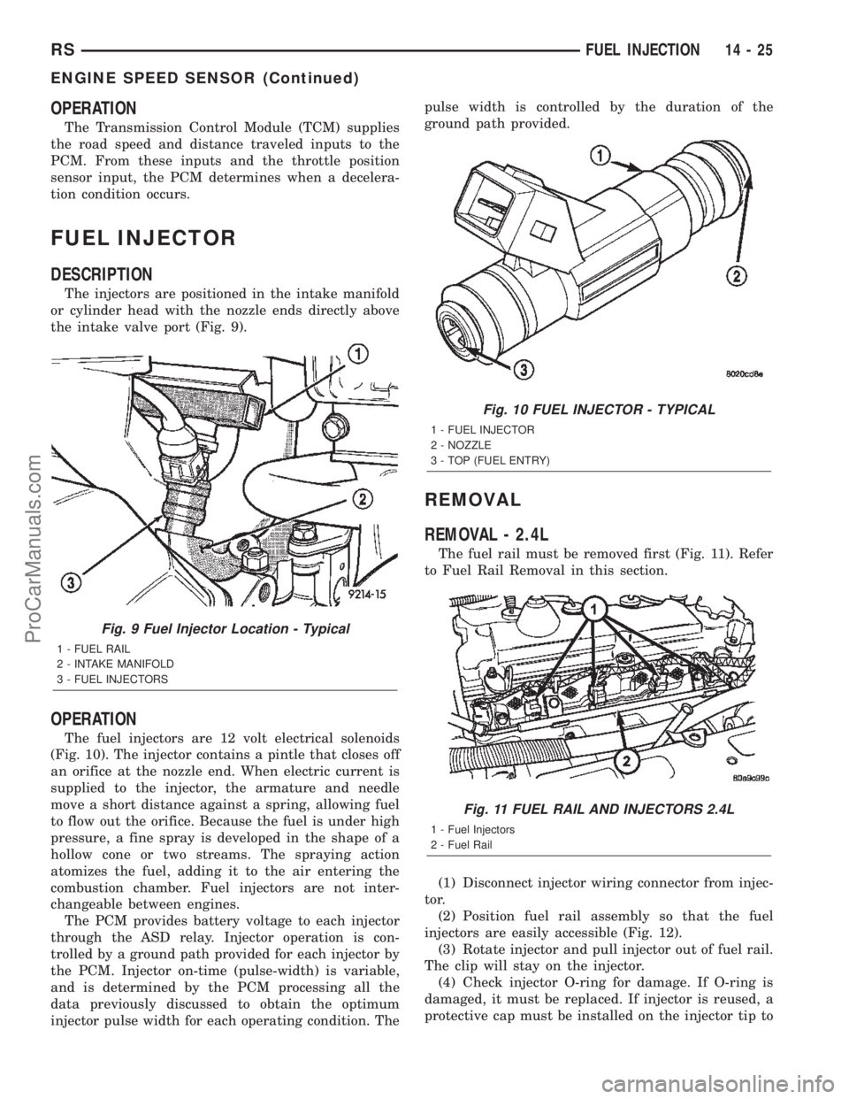
or cylinder head with the nozzle ends directly above
the intake valve port (Fig. 9).
OPERATION
The fuel injectors are 12 volt electrical solenoids
(Fig. 10). The injector contains a pintle that closes off
an orifice at the nozzle end. When electric current is
supplied to the injector, the armature and needle
move a short distance against a spring, allowing fuel
to flow out the orifice. Because the fuel is under high
pressure, a fine spray is developed in the shape of a
hollow cone or two streams. The spraying action
atomizes the fuel, adding it to the air entering the
combustion chamber. Fuel injectors are not inter-
changeable between engines.
The PCM provides battery voltage to each injector
through the ASD relay. Injector operation is con-
trolled by a ground path provided for each injector by
the PCM. Injector on-time (pulse-width) is variable,
and is determined by the PCM processing all the
data previously discussed to obtain the optimum
injector pulse width for each operating condition. Thepulse width is controlled by the duration of the
ground path provided.
REMOVAL
REMOVAL - 2.4L
The fuel rail must be removed first (Fig. 11). Refer
to Fuel Rail Removal in this section.
(1) Disconnect injector wiring connector from injec-
tor.
(2) Position fuel rail assembly so that the fuel
injectors are easily accessible (Fig. 12).
(3) Rotate injector and pull injector out of fuel rail.
The clip will stay on the injector.
(4) Check injector O-ring for damage. If O-ring is
damaged, it must be replaced. If injector is reused, a
protective cap must be installed on the injector tip to
Fig. 9 Fuel Injector Location - Typical
1 - FUEL RAIL
2 - INTAKE MANIFOLD
3 - FUEL INJECTORS
Fig. 10 FUEL INJECTOR - TYPICAL
1 - FUEL INJECTOR
2 - NOZZLE
3 - TOP (FUEL ENTRY)
Fig. 11 FUEL RAIL AND INJECTORS 2.4L
1 - Fuel Injectors
2 - Fuel Rail
RSFUEL INJECTION14-25
ENGINE SPEED SENSOR (Continued)
ProCarManuals.com
Page 1477 of 2399
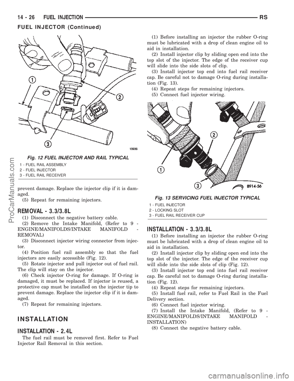
prevent damage. Replace the injector clip if it is dam-
aged.
(5) Repeat for remaining injectors.
REMOVAL - 3.3/3.8L
(1) Disconnect the negative battery cable.
(2) Remove the Intake Manifold, (Refer to 9 -
ENGINE/MANIFOLDS/INTAKE MANIFOLD -
REMOVAL)
(3) Disconnect injector wiring connector from injec-
tor.
(4) Position fuel rail assembly so that the fuel
injectors are easily accessible (Fig. 12).
(5) Rotate injector and pull injector out of fuel rail.
The clip will stay on the injector.
(6) Check injector O-ring for damage. If O-ring is
damaged, it must be replaced. If injector is reused, a
protective cap must be installed on the injector tip to
prevent damage. Replace the injector clip if it is dam-
aged.
(7) Repeat for remaining injectors.
INSTALLATION
INSTALLATION - 2.4L
The fuel rail must be removed first. Refer to Fuel
Injector Rail Removal in this section.(1) Before installing an injector the rubber O-ring
must be lubricated with a drop of clean engine oil to
aid in installation.
(2) Install injector clip by sliding open end into the
top slot of the injector. The edge of the receiver cup
will slide into the side slots of clip.
(3) Install injector top end into fuel rail receiver
cap. Be careful not to damage O-ring during installa-
tion (Fig. 13).
(4) Repeat steps for remaining injectors.
(5) Connect fuel injector wiring.
INSTALLATION - 3.3/3.8L
(1) Before installing an injector the rubber O-ring
must be lubricated with a drop of clean engine oil to
aid in installation.
(2) Install injector clip by sliding open end into the
top slot of the injector. The edge of the receiver cup
will slide into the side slots of clip (Fig. 12).
(3) Install injector top end into fuel rail receiver
cap. Be careful not to damage O-ring during installa-
tion (Fig. 12).
(4) Repeat steps for remaining injectors.
(5) Install fuel rail, refer to Fuel Rail in the Fuel
Delivery section.
(6) Connect fuel injector wiring.
(7) Install the Intake Manifold, (Refer to 9 -
ENGINE/MANIFOLDS/INTAKE MANIFOLD -
INSTALLATION)
(8) Connect the negative battery cable.
Fig. 12 FUEL INJECTOR AND RAIL TYPICAL
1 - FUEL RAIL ASSEMBLY
2 - FUEL INJECTOR
3 - FUEL RAIL RECEIVER
Fig. 13 SERVICING FUEL INJECTOR TYPICAL
1 - FUEL INJECTOR
2 - LOCKING SLOT
3 - FUEL RAIL RECEIVER CUP
14 - 26 FUEL INJECTIONRS
FUEL INJECTOR (Continued)
ProCarManuals.com
Page 1482 of 2399
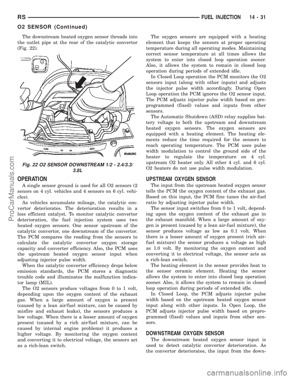
The downstream heated oxygen sensor threads into
the outlet pipe at the rear of the catalytic convertor
(Fig. 22).
OPERATION
A single sensor ground is used for all O2 sensors (2
senors on 4 cyl. vehicles and 4 sensors on 6 cyl. vehi-
cles).
As vehicles accumulate mileage, the catalytic con-
vertor deteriorates. The deterioration results in a
less efficient catalyst. To monitor catalytic convertor
deterioration, the fuel injection system uses two
heated oxygen sensors. One sensor upstream of the
catalytic convertor, one downstream of the convertor.
The PCM compares the reading from the sensors to
calculate the catalytic convertor oxygen storage
capacity and converter efficiency. Also, the PCM uses
the upstream heated oxygen sensor input when
adjusting injector pulse width.
When the catalytic converter efficiency drops below
emission standards, the PCM stores a diagnostic
trouble code and illuminates the malfunction indica-
tor lamp (MIL).
The O2 sensors produce voltages from 0 to 1 volt,
depending upon the oxygen content of the exhaust
gas. When a large amount of oxygen is present
(caused by a lean air/fuel mixture, can be caused by
misfire and exhaust leaks), the sensors produces a
low voltage. When there is a lesser amount of oxygen
present (caused by a rich air/fuel mixture, can be
caused by internal engine problems) it produces a
higher voltage. By monitoring the oxygen content
and converting it to electrical voltage, the sensors act
as a rich-lean switch.The oxygen sensors are equipped with a heating
element that keeps the sensors at proper operating
temperature during all operating modes. Maintaining
correct sensor temperature at all times allows the
system to enter into closed loop operation sooner.
Also, it allows the system to remain in closed loop
operation during periods of extended idle.
In Closed Loop operation the PCM monitors the O2
sensors input (along with other inputs) and adjusts
the injector pulse width accordingly. During Open
Loop operation the PCM ignores the O2 sensor input.
The PCM adjusts injector pulse width based on pre-
programmed (fixed) values and inputs from other
sensors.
The Automatic Shutdown (ASD) relay supplies bat-
tery voltage to both the upstream and downstream
heated oxygen sensors. The oxygen sensors are
equipped with a heating element. The heating ele-
ments reduce the time required for the sensors to
reach operating temperature. The PCM uses pulse
width modulation to control the ground side of the
heater to regulate the temperature on 4 cyl.
upstream O2 heater only. All other 4 cyl. and 6 cyl.
O2 heaters do not use pulse width modulation.
UPSTREAM OXYGEN SENSOR
The input from the upstream heated oxygen sensor
tells the PCM the oxygen content of the exhaust gas.
Based on this input, the PCM fine tunes the air-fuel
ratio by adjusting injector pulse width.
The sensor input switches from 0 to 1 volt, depend-
ing upon the oxygen content of the exhaust gas in
the exhaust manifold. When a large amount of oxy-
gen is present (caused by a lean air-fuel mixture), the
sensor produces voltage as low as 0.1 volt. When
there is a lesser amount of oxygen present (rich air-
fuel mixture) the sensor produces a voltage as high
as 1.0 volt. By monitoring the oxygen content and
converting it to electrical voltage, the sensor acts as
a rich-lean switch.
The heating element in the sensor provides heat to
the sensor ceramic element. Heating the sensor
allows the system to enter into closed loop operation
sooner. Also, it allows the system to remain in closed
loop operation during periods of extended idle.
In Closed Loop, the PCM adjusts injector pulse
width based on the upstream heated oxygen sensor
input along with other inputs. In Open Loop, the
PCM adjusts injector pulse width based on prepro-
grammed (fixed) values and inputs from other sen-
sors.
DOWNSTREAM OXYGEN SENSOR
The downstream heated oxygen sensor input is
used to detect catalytic convertor deterioration. As
the convertor deteriorates, the input from the down-
Fig. 22 O2 SENSOR DOWNSTREAM 1/2 - 2.4/3.3/
3.8L
RSFUEL INJECTION14-31
O2 SENSOR (Continued)
ProCarManuals.com
Page 1488 of 2399
FUEL SYSTEM
TABLE OF CONTENTS
page page
FUEL SYSTEM 2.5L TURBO DIESEL
DESCRIPTION - DIESEL FUEL DELIVERY
SYSTEM.............................1
WARNING - HIGH FUEL SYSTEM PRESSURE . . 1
DIAGNOSIS AND TESTING
DIAGNOSIS AND TESTING - AIR IN FUEL
SYSTEM.............................1
DIAGNOSIS AND TESTING - FUEL SUPPLY
RESTRICTIONS........................1
STANDARD PROCEDURE
STANDARD PROCEDURES - DRAINING
WATER FROM FUEL FILTER..............2STANDARD PROCEDURE - FUEL SYSTEM
AIR PURGE...........................2
STANDARD PROCEDURES - CLEANING
FUEL SYSTEM COMPONENTS............2
SPECIFICATIONS - TORQUE...............3
FUEL DELIVERY..........................4
FUEL INJECTION........................11
FUEL SYSTEM 2.5L TURBO
DIESEL
DESCRIPTION - DIESEL FUEL DELIVERY
SYSTEM
The fuel system on the 2.5L Common Rail Diesel
Engine uses a fuel injection pump and an Electronic
Control Module (ECM).
The fuel delivery system consists of the:
²Accelerator pedal
²Air cleaner housing/element
²Fuel filter/water separator
²Fuel heater
²Fuel heater relay
²Fuel transfer (lift) pump
²Fuel injection pump
²Fuel injectors
²Fuel tank
²Fuel tank filler/vent tube assembly
²Fuel tank filler tube cap
²Fuel tank module containing the rollover valve
and a fuel gauge sending unit (fuel level sensor).
²Fuel tubes/lines/hoses
²High-pressure fuel injector lines
²Low-pressure fuel supply lines
²Low-pressure fuel return line
²Overflow valve
²Quick-connect fittings
²Water draining
WARNING - HIGH FUEL SYSTEM PRESSURE
WARNING:: THE INJECTION PUMP SUPPLIES HIGH-
PRESSURE FUEL TO EACH INDIVIDUAL INJECTOR
THROUGH HIGH-PRESSURE LINES. FUEL UNDERTHIS AMOUNT OF PRESSURE CAN PENETRATE
SKIN AND CAUSE PERSONAL INJURY. WEAR
SAFETY GOGGLES AND ADEQUATE PROTECTIVE
CLOTHING. AVOID CONTACT WITH FUEL SPRAY
WHEN BLEEDING HIGH-PRESSURE FUEL LINES.
DIAGNOSIS AND TESTING
DIAGNOSIS AND TESTING - AIR IN FUEL
SYSTEM
Air will enter the fuel system whenever fuel supply
lines, separator filters, injection pump, high-pressure
lines or injectors are removed or disconnected. Air
trapped in the fuel system can result in hard start-
ing, a rough running engine, engine misfire, low
power, excessive smoke and fuel knock. After service
is performed, air must be bled from the system
before starting the engine.
Inspect the fuel system from the fuel tank to the
injectors for loose connections. Leaking fuel is an
indicator of loose connections or defective seals. Air
can also enter the fuel system between the fuel tank
and the transfer pump. Inspect the fuel tank and fuel
lines for damage that might allow air into the sys-
tem.
DIAGNOSIS AND TESTING - FUEL SUPPLY
RESTRICTIONS
LOW-PRESSURE LINES
Fuel supply line restrictions or a defective fuel
transfer pump can cause starting problems and pre-
vent engine from accelerating. The starting problems
include; low power and/or white fog like exhaust.
RGFUEL SYSTEM14a-1
ProCarManuals.com
Page 1489 of 2399
Test all fuel supply lines for restrictions or block-
age. Flush or replace as necessary. Bleed fuel system
of air once a fuel supply line has been replaced. Refer
to Air Bleed Procedure for procedures.
To test for fuel line restrictions, a vacuum restric-
tion test may be performed.
HIGH-PRESSURE LINES
Restricted (kinked or bent) high-pressure lines can
cause starting problems, poor engine performance,
engine mis-fire and white smoke from exhaust.
Examine all high-pressure lines for any damage.
Each radius on each high-pressure line must be
smooth and free of any bends or kinks.
Replace damaged, restricted or leaking high-pres-
sure fuel lines with correct replacement line.
CAUTION: High pressure lines cannot contact each
other or other components. Do not attempt to weld
high-pressure fuel lines or to repair lines that are
damaged. If line is kinked or bent, it must be
replaced. Use only recommended lines when
replacement of high-pressure fuel line is necessary.
STANDARD PROCEDURE
STANDARD PROCEDURES - DRAINING WATER
FROM FUEL FILTER
Refer to Fuel Filter/Water Separator removal/in-
stallation for procedures.
STANDARD PROCEDURE - FUEL SYSTEM AIR
PURGE
(1) Remove engine cover (Refer to 9 - ENGINE
COVER - REMOVAL).
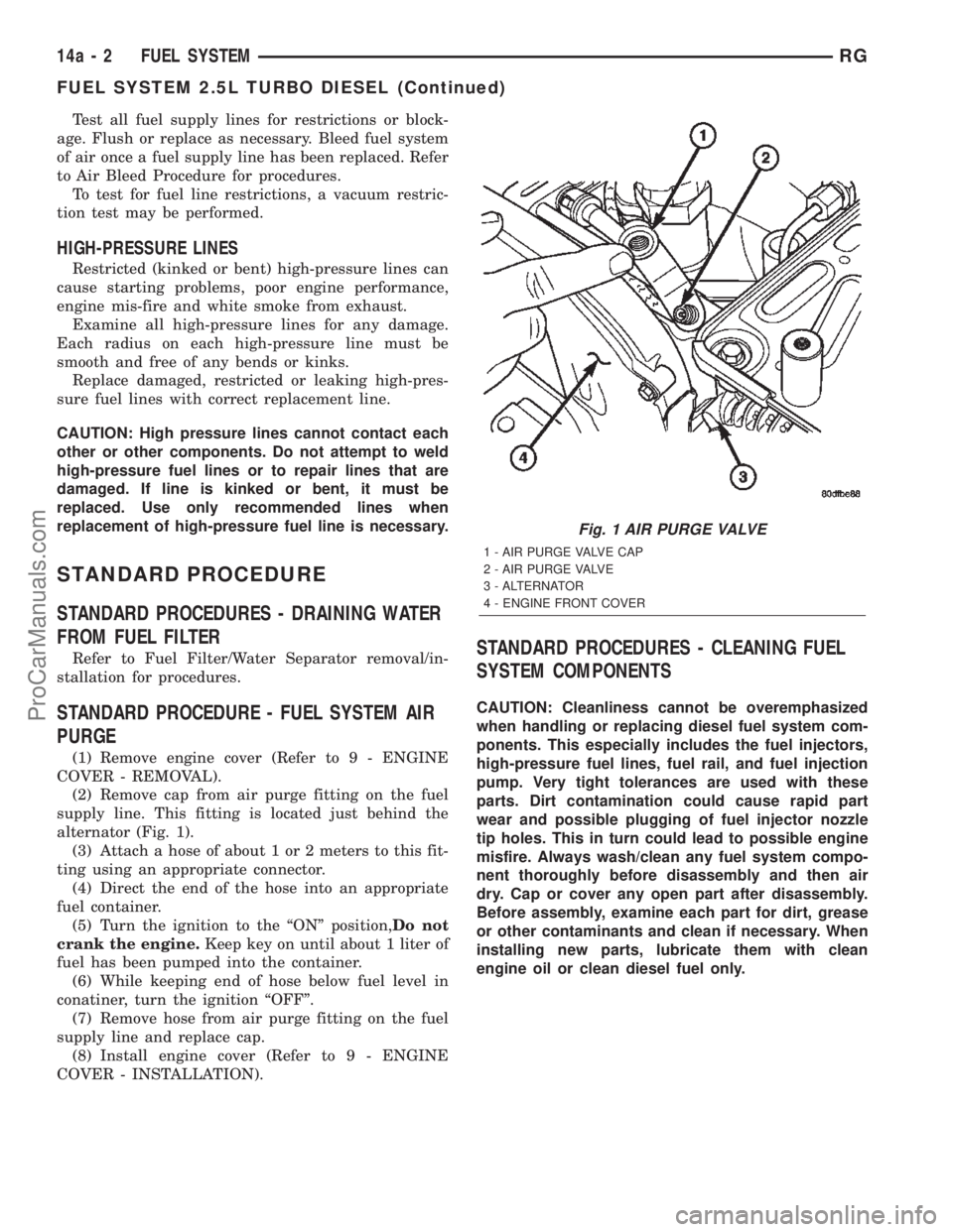
(2) Remove cap from air purge fitting on the fuel
supply line. This fitting is located just behind the
alternator (Fig. 1).
(3) Attach a hose of about 1 or 2 meters to this fit-
ting using an appropriate connector.
(4) Direct the end of the hose into an appropriate
fuel container.
(5) Turn the ignition to the ªONº position,Do not
crank the engine.Keep key on until about 1 liter of
fuel has been pumped into the container.
(6) While keeping end of hose below fuel level in
conatiner, turn the ignition ªOFFº.
(7) Remove hose from air purge fitting on the fuel
supply line and replace cap.
(8) Install engine cover (Refer to 9 - ENGINE
COVER - INSTALLATION).
STANDARD PROCEDURES - CLEANING FUEL
SYSTEM COMPONENTS
CAUTION: Cleanliness cannot be overemphasized
when handling or replacing diesel fuel system com-
ponents. This especially includes the fuel injectors,
high-pressure fuel lines, fuel rail, and fuel injection
pump. Very tight tolerances are used with these
parts. Dirt contamination could cause rapid part
wear and possible plugging of fuel injector nozzle
tip holes. This in turn could lead to possible engine
misfire. Always wash/clean any fuel system compo-
nent thoroughly before disassembly and then air
dry. Cap or cover any open part after disassembly.
Before assembly, examine each part for dirt, grease
or other contaminants and clean if necessary. When
installing new parts, lubricate them with clean
engine oil or clean diesel fuel only.
Fig. 1 AIR PURGE VALVE
1 - AIR PURGE VALVE CAP
2 - AIR PURGE VALVE
3 - ALTERNATOR
4 - ENGINE FRONT COVER
14a - 2 FUEL SYSTEMRG
FUEL SYSTEM 2.5L TURBO DIESEL (Continued)
ProCarManuals.com