2002 CHRYSLER TOWN AND COUNTRY brakes
[x] Cancel search: brakesPage 832 of 2399
8W-35 ANTILOCK BRAKES
Component Page
Body Control Module................. 8W-35-2
Brake Lamp Switch.................. 8W-35-3
Controller Antilock Brake.......... 8W-35-2, 3, 4
Diagnostic Junction Port............... 8W-35-3
Engine Control Module................ 8W-35-3
Front Control Module................. 8W-35-3
Fuse 9............................. 8W-35-2
Fuse 21............................ 8W-35-2
Fuse 26............................ 8W-35-3
G100.............................. 8W-35-2Component Page
G200.............................. 8W-35-2
G300.............................. 8W-35-3
Integrated Power Module............ 8W-35-2, 3
Left Front Wheel Speed Sensor......... 8W-35-4
Left Rear Wheel Speed Sensor.......... 8W-35-4
Powertrain Control Module............. 8W-35-3
Right Front Wheel Speed Sensor........ 8W-35-4
Right Rear Wheel Speed Sensor......... 8W-35-4
Traction Control Switch............... 8W-35-2
RS8W-35 ANTILOCK BRAKES8W-35-1
ProCarManuals.com
Page 1046 of 2399
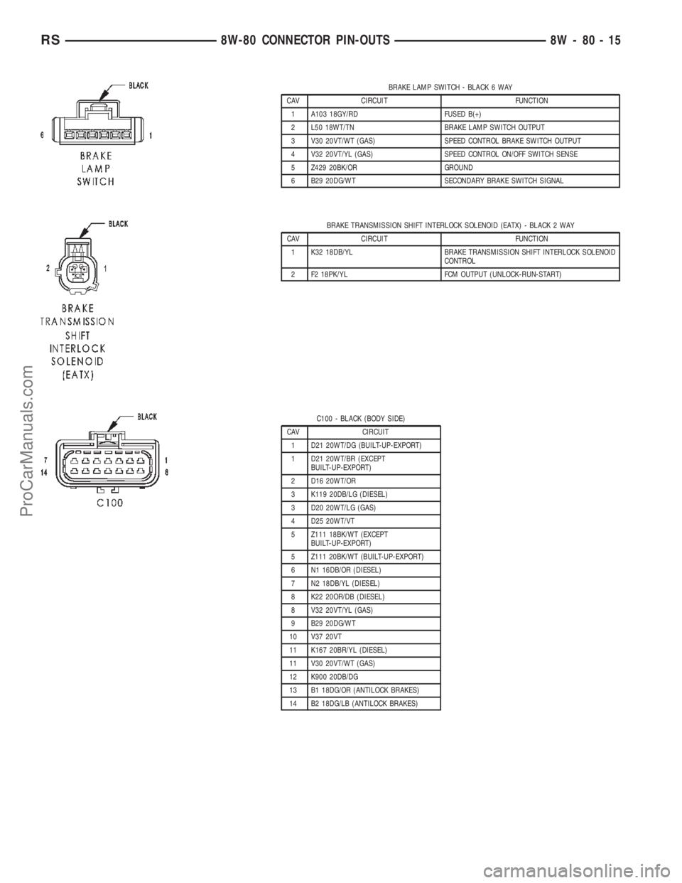
BRAKE LAMP SWITCH - BLACK 6 WAY
CAV CIRCUIT FUNCTION
1 A103 18GY/RD FUSED B(+)
2 L50 18WT/TN BRAKE LAMP SWITCH OUTPUT
3 V30 20VT/WT (GAS) SPEED CONTROL BRAKE SWITCH OUTPUT
4 V32 20VT/YL (GAS) SPEED CONTROL ON/OFF SWITCH SENSE
5 Z429 20BK/OR GROUND
6 B29 20DG/WT SECONDARY BRAKE SWITCH SIGNAL
BRAKE TRANSMISSION SHIFT INTERLOCK SOLENOID (EATX) - BLACK 2 WAY
CAV CIRCUIT FUNCTION
1 K32 18DB/YL BRAKE TRANSMISSION SHIFT INTERLOCK SOLENOID
CONTROL
2 F2 18PK/YL FCM OUTPUT (UNLOCK-RUN-START)
C100 - BLACK (BODY SIDE)
CAV CIRCUIT
1 D21 20WT/DG (BUILT-UP-EXPORT)
1 D21 20WT/BR (EXCEPT
BUILT-UP-EXPORT)
2 D16 20WT/OR
3 K119 20DB/LG (DIESEL)
3 D20 20WT/LG (GAS)
4 D25 20WT/VT
5 Z111 18BK/WT (EXCEPT
BUILT-UP-EXPORT)
5 Z111 20BK/WT (BUILT-UP-EXPORT)
6 N1 16DB/OR (DIESEL)
7 N2 18DB/YL (DIESEL)
8 K22 20OR/DB (DIESEL)
8 V32 20VT/YL (GAS)
9 B29 20DG/WT
10 V37 20VT
11 K167 20BR/YL (DIESEL)
11 V30 20VT/WT (GAS)
12 K900 20DB/DG
13 B1 18DG/OR (ANTILOCK BRAKES)
14 B2 18DG/LB (ANTILOCK BRAKES)
RS8W-80 CONNECTOR PIN-OUTS8W-80-15
ProCarManuals.com
Page 1047 of 2399
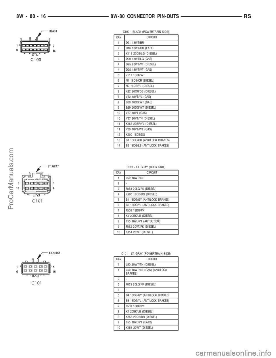
C100 - BLACK (POWERTRAIN SIDE)
CAV CIRCUIT
1 D21 18WT/BR
2 D16 18WT/OR (EATX)
3 K119 20DB/LG (DIESEL)
3 D20 18WT/LG (GAS)
4 D25 20WT/VT (DIESEL)
4 D25 18WT/VT (GAS)
5 Z111 18BK/WT
6 N1 18DB/OR (DIESEL)
7 N2 18DB/YL (DIESEL)
8 K22 20OR/DB (DIESEL)
8 V32 18VT/YL (GAS)
9 B29 18DG/WT (GAS)
9 B29 20DG/WT (DIESEL)
10 V37 18VT (GAS)
10 V37 20VT/TN (DIESEL)
11 K167 20BR/YL (DIESEL)
11 V30 18VT/WT (GAS)
12 K900 18DB/DG
13 B1 18DG/OR (ANTILOCK BRAKES)
14 B2 18DG/LB (ANTILOCK BRAKES)
C101 - LT. GRAY (BODY SIDE)
CAV CIRCUIT
1 L50 18WT/TN
2-
3 F853 20LG/PK (DIESEL)
4 K900 18DB/DG (DIESEL)
5 B4 18DG/GY (ANTILOCK BRAKES)
6 B3 18DG/YL (ANTILOCK BRAKES)
7 F500 18DG/PK
8 K4 20BK/LB (DIESEL)
9 T55 18YL/VT (AUTOSTICK)
9 F852 20VT/PK (DIESEL)
10 K151 20WT (DIESEL)
C101 - LT. GRAY (POWERTRAIN SIDE)
CAV CIRCUIT
1 L50 20WT/TN (DIESEL)
1 L50 18WT/TN (GAS) (ANTILOCK
BRAKES)
2-
3 F853 20LG/PK (DIESEL)
4-
5 B4 18DG/GY (ANTILOCK BRAKES)
6 B3 18DG/YL (ANTILOCK BRAKES)
7 F500 18DG/PK
8 K4 20BK/LB (DIESEL)
9 K853 20DB/BR (DIESEL)
9 T55 18YL/VT (EATX)
10 K151 20WT (DIESEL)
8W - 80 - 16 8W-80 CONNECTOR PIN-OUTSRS
ProCarManuals.com
Page 1100 of 2399
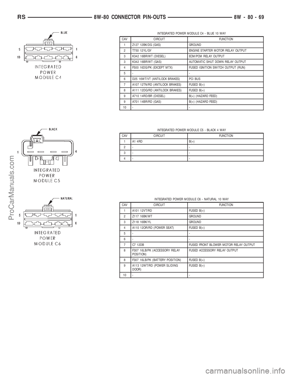
INTEGRATED POWER MODULE C4 - BLUE 10 WAY
CAV CIRCUIT FUNCTION
1 Z127 12BK/DG (GAS) GROUND
2 T750 12YL/GY ENGINE STARTER MOTOR RELAY OUTPUT
3 K342 16BR/WT (DIESEL) ECM/PCM RELAY OUTPUT
3 K342 16BR/WT (GAS) AUTOMATIC SHUT DOWN RELAY OUTPUT
4 F500 16DG/PK (EXCEPT MTX) FUSED IGNITION SWITCH OUTPUT (RUN)
5- -
6 D25 16WT/VT (ANTILOCK BRAKES) PCI BUS
7 A107 12TN/RD (ANTILOCK BRAKES) FUSED B(+)
8 A111 12DG/RD (ANTILOCK BRAKES) FUSED B(+)
9 A710 14RD/BR (DIESEL) B(+) (HAZARD FEED)
9 A701 14BR/RD (GAS) B(+) (HAZARD FEED)
10 - -
INTEGRATED POWER MODULE C5 - BLACK 4 WAY
CAV CIRCUIT FUNCTION
1 A1 4RD B(+)
2- -
3- -
4- -
INTEGRATED POWER MODULE C6 - NATURAL 10 WAY
CAV CIRCUIT FUNCTION
1 A101 12VT/RD FUSED B(+)
2 Z117 16BK/WT GROUND
3 Z118 16BK/YL GROUND
4 A110 12OR/RD (POWER SEAT) FUSED B(+)
5- -
6- -
7 C7 12DB FUSED FRONT BLOWER MOTOR RELAY OUTPUT
8 F307 16LB/PK (ACCESSORY RELAY
POSITION)FUSED ACCESSORY RELAY OUTPUT
8 F307 16LB/PK (BATTERY POSITION) FUSED B(+)
9 A113 12WT/RD (POWER SLIDING
DOOR)FUSED B(+)
10 - -
RS8W-80 CONNECTOR PIN-OUTS8W-80-69
ProCarManuals.com
Page 1657 of 2399
(8) Start engine and allow to idle for at least one
minute. Then, with parking and service brakes
applied, move selector lever momentarily to each
position, ending in the park or neutral position.
(9) Check the transaxle fluid level and add an
appropriate amount to bring the transaxle fluid level
to 3mm (1/8 in.) below the ªADDº mark on the dip-
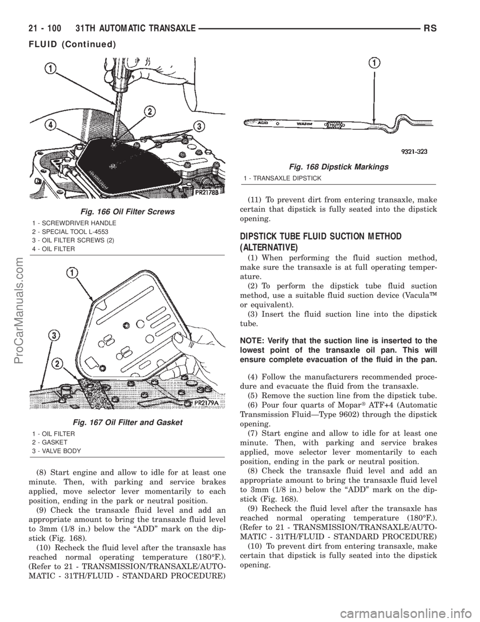
stick (Fig. 168).
(10) Recheck the fluid level after the transaxle has
reached normal operating temperature (180ÉF.).
(Refer to 21 - TRANSMISSION/TRANSAXLE/AUTO-
MATIC - 31TH/FLUID - STANDARD PROCEDURE)(11) To prevent dirt from entering transaxle, make
certain that dipstick is fully seated into the dipstick
opening.
DIPSTICK TUBE FLUID SUCTION METHOD
(ALTERNATIVE)
(1) When performing the fluid suction method,
make sure the transaxle is at full operating temper-
ature.
(2) To perform the dipstick tube fluid suction
method, use a suitable fluid suction device (VaculaŸ
or equivalent).
(3) Insert the fluid suction line into the dipstick
tube.
NOTE: Verify that the suction line is inserted to the
lowest point of the transaxle oil pan. This will
ensure complete evacuation of the fluid in the pan.
(4) Follow the manufacturers recommended proce-
dure and evacuate the fluid from the transaxle.
(5) Remove the suction line from the dipstick tube.
(6) Pour four quarts of MopartATF+4 (Automatic
Transmission FluidÐType 9602) through the dipstick
opening.
(7) Start engine and allow to idle for at least one
minute. Then, with parking and service brakes
applied, move selector lever momentarily to each
position, ending in the park or neutral position.
(8) Check the transaxle fluid level and add an
appropriate amount to bring the transaxle fluid level
to 3mm (1/8 in.) below the ªADDº mark on the dip-
stick (Fig. 168).
(9) Recheck the fluid level after the transaxle has
reached normal operating temperature (180ÉF.).
(Refer to 21 - TRANSMISSION/TRANSAXLE/AUTO-
MATIC - 31TH/FLUID - STANDARD PROCEDURE)
(10) To prevent dirt from entering transaxle, make
certain that dipstick is fully seated into the dipstick
opening.
Fig. 166 Oil Filter Screws
1 - SCREWDRIVER HANDLE
2 - SPECIAL TOOL L-4553
3 - OIL FILTER SCREWS (2)
4 - OIL FILTER
Fig. 167 Oil Filter and Gasket
1 - OIL FILTER
2 - GASKET
3 - VALVE BODY
Fig. 168 Dipstick Markings
1 - TRANSAXLE DIPSTICK
21 - 100 31TH AUTOMATIC TRANSAXLERS
FLUID (Continued)
ProCarManuals.com
Page 1807 of 2399
(6) Adjust transmission fluid level shown on the
indicator according to the chart.
(7) Check transmission for leaks.
Low fluid level can cause a variety of conditions
because it allows the pump to take in air along with
the fluid. As in any hydraulic system, air bubbles
make the fluid spongy, therefore, pressures will be
low and build up slowly.
Improper filling can also raise the fluid level too
high. When the transaxle has too much fluid, the
gears churn up foam and cause the same conditions
which occur with a low fluid level.
In either case, air bubbles can cause overheating
and/or fluid oxidation, and varnishing. This can
interfere with normal valve, clutch, and accumulator
operation. Foaming can also result in fluid escaping
from the transaxle vent where it may be mistaken
for a leak.
FLUID CONDITION
Along with fluid level, it is important to check the
condition of the fluid. When the fluid smells burned,
and is contaminated with metal or friction material
particles, a complete transaxle recondition is proba-
bly required. Be sure to examine the fluid on the dip-
stick closely. If there is any doubt about its condition,
drain out a sample for a double check.
MopartATF+4 (Automatic Transmission Fluid-
Type 9602) when new is red in color. The ATF is dyed
red so it can be identified from other fluids used in
the vehicle such as engine oil or antifreeze. The red
color is not permanent and is not an indicator of fluid
condition. As the vehicle is driven, the ATF will begin
to look darker in color and may eventually become
brown.This is normal.ATF+4 also has a unique
odor that may change with age. Consequently,odor
and color cannot be used to indicate the fluid
condition or the need for a fluid change.
After the fluid has been checked, seat the dipstick
fully to seal out water and dirt.
STANDARD PROCEDURE - FLUID AND FILTER
SERVICE
NOTE: Refer to the maintenance schedules in
LUBRICATION and MAINTENANCE, or the vehicle
owner's manual, for the recommended maintenance
(fluid/filter change) intervals for this transaxle.
NOTE: Only fluids of the type labeled MoparTATF+4
(Automatic Transmission Fluid) Type 9602 should
be used. A filter change should be made at the time
of the transmission oil change. The magnet (on the
inside of the oil pan) should also be cleaned with a
clean, dry cloth.NOTE: If the transaxle is disassembled for any rea-
son, the fluid and filter should be changed.
FLUID/FILTER SERVICE (RECOMMENDED)
(1) Raise vehicle on a hoist. Refer to LUBRICA-
TION and MAINTENANCE for proper procedures.
Place a drain container with a large opening, under
transaxle oil pan.
(2) Loosen pan bolts and tap the pan at one corner
to break it loose allowing fluid to drain, then remove
the oil pan.
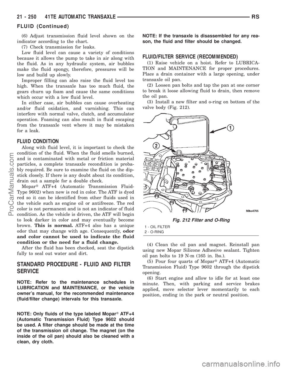
(3) Install a new filter and o-ring on bottom of the
valve body (Fig. 212).
(4) Clean the oil pan and magnet. Reinstall pan
using new Mopar Silicone Adhesive sealant. Tighten
oil pan bolts to 19 N´m (165 in. lbs.).
(5) Pour four quarts of MopartATF+4 (Automatic
Transmission Fluid) Type 9602 through the dipstick
opening.
(6) Start engine and allow to idle for at least one
minute. Then, with parking and service brakes
applied, move selector lever momentarily to each
position, ending in the park or neutral position.
Fig. 212 Filter and O-Ring
1 - OIL FILTER
2 - O-RING
21 - 250 41TE AUTOMATIC TRANSAXLERS
FLUID (Continued)
ProCarManuals.com
Page 1808 of 2399
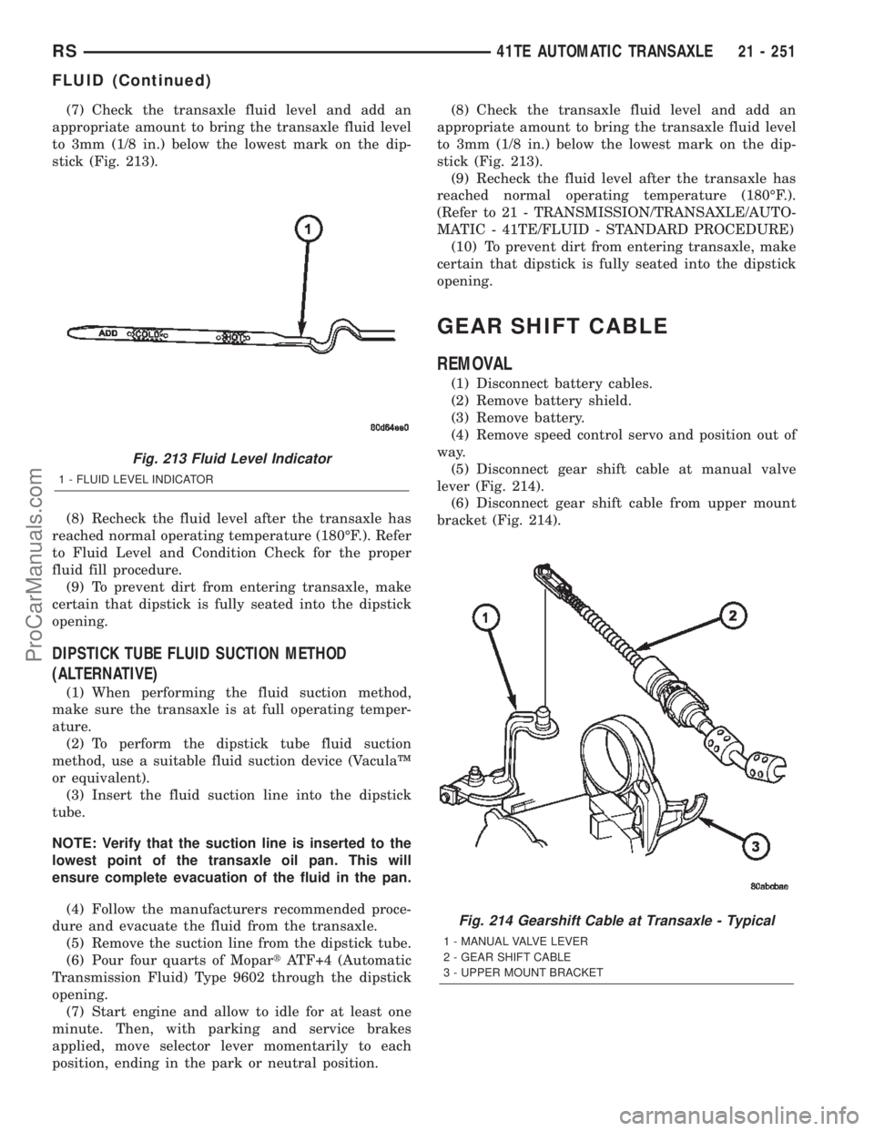
(7) Check the transaxle fluid level and add an
appropriate amount to bring the transaxle fluid level
to 3mm (1/8 in.) below the lowest mark on the dip-
stick (Fig. 213).
(8) Recheck the fluid level after the transaxle has
reached normal operating temperature (180ÉF.). Refer
to Fluid Level and Condition Check for the proper
fluid fill procedure.
(9) To prevent dirt from entering transaxle, make
certain that dipstick is fully seated into the dipstick
opening.
DIPSTICK TUBE FLUID SUCTION METHOD
(ALTERNATIVE)
(1) When performing the fluid suction method,
make sure the transaxle is at full operating temper-
ature.
(2) To perform the dipstick tube fluid suction
method, use a suitable fluid suction device (VaculaŸ
or equivalent).
(3) Insert the fluid suction line into the dipstick
tube.
NOTE: Verify that the suction line is inserted to the
lowest point of the transaxle oil pan. This will
ensure complete evacuation of the fluid in the pan.
(4) Follow the manufacturers recommended proce-
dure and evacuate the fluid from the transaxle.
(5) Remove the suction line from the dipstick tube.
(6) Pour four quarts of MopartATF+4 (Automatic
Transmission Fluid) Type 9602 through the dipstick
opening.
(7) Start engine and allow to idle for at least one
minute. Then, with parking and service brakes
applied, move selector lever momentarily to each
position, ending in the park or neutral position.(8) Check the transaxle fluid level and add an
appropriate amount to bring the transaxle fluid level
to 3mm (1/8 in.) below the lowest mark on the dip-
stick (Fig. 213).
(9) Recheck the fluid level after the transaxle has
reached normal operating temperature (180ÉF.).
(Refer to 21 - TRANSMISSION/TRANSAXLE/AUTO-
MATIC - 41TE/FLUID - STANDARD PROCEDURE)
(10) To prevent dirt from entering transaxle, make
certain that dipstick is fully seated into the dipstick
opening.
GEAR SHIFT CABLE
REMOVAL
(1) Disconnect battery cables.
(2) Remove battery shield.
(3) Remove battery.
(4) Remove speed control servo and position out of
way.
(5) Disconnect gear shift cable at manual valve
lever (Fig. 214).
(6) Disconnect gear shift cable from upper mount
bracket (Fig. 214).
Fig. 213 Fluid Level Indicator
1 - FLUID LEVEL INDICATOR
Fig. 214 Gearshift Cable at Transaxle - Typical
1 - MANUAL VALVE LEVER
2 - GEAR SHIFT CABLE
3 - UPPER MOUNT BRACKET
RS41TE AUTOMATIC TRANSAXLE21 - 251
FLUID (Continued)
ProCarManuals.com
Page 1963 of 2399
Inspect for the following:
²Verify correct (OEM) wheel and tire, as well as
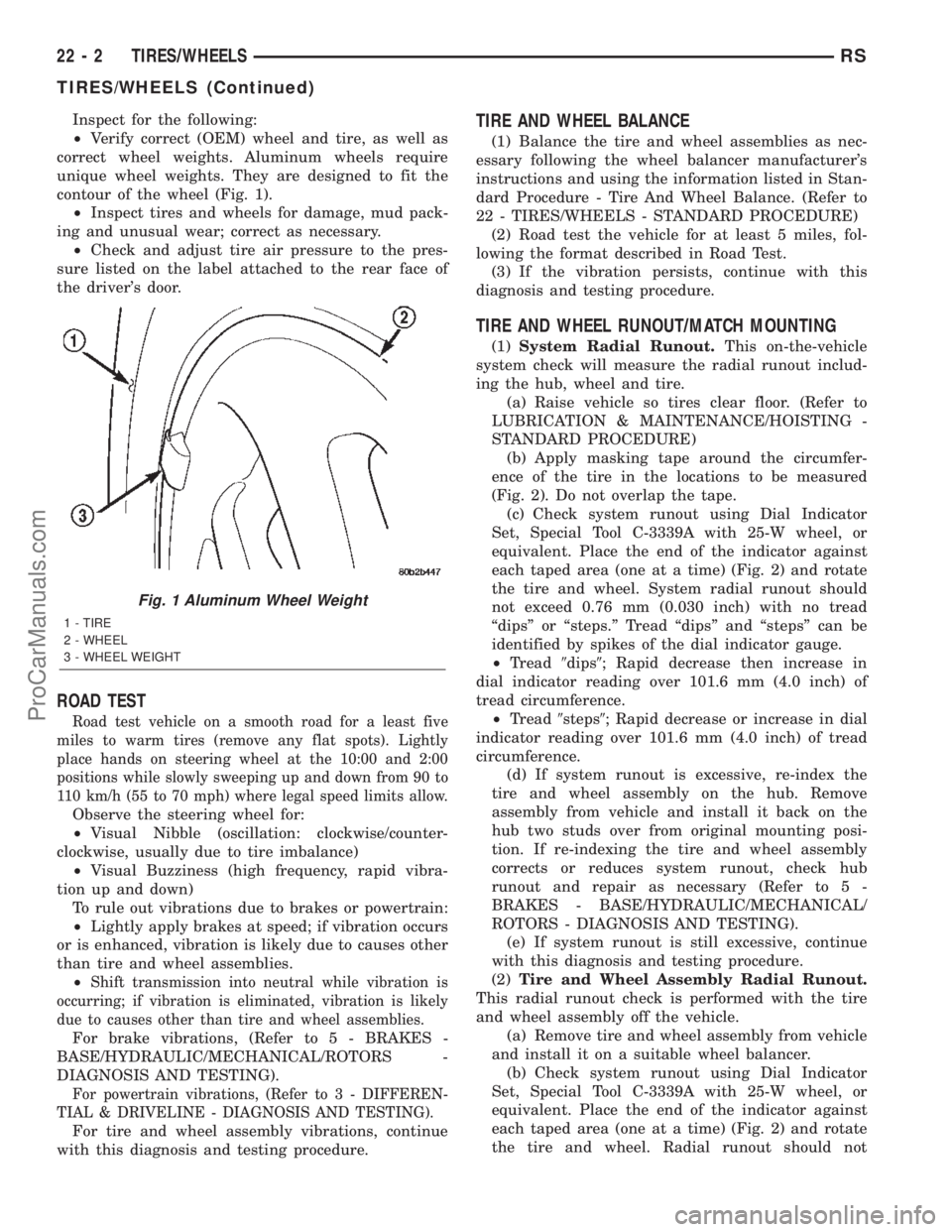
correct wheel weights. Aluminum wheels require
unique wheel weights. They are designed to fit the
contour of the wheel (Fig. 1).
²Inspect tires and wheels for damage, mud pack-
ing and unusual wear; correct as necessary.
²Check and adjust tire air pressure to the pres-
sure listed on the label attached to the rear face of
the driver's door.
ROAD TEST
Road test vehicle on a smooth road for a least five
miles to warm tires (remove any flat spots). Lightly
place hands on steering wheel at the 10:00 and 2:00
positions while slowly sweeping up and down from 90 to
110 km/h (55 to 70 mph) where legal speed limits allow.
Observe the steering wheel for:
²Visual Nibble (oscillation: clockwise/counter-
clockwise, usually due to tire imbalance)
²Visual Buzziness (high frequency, rapid vibra-
tion up and down)
To rule out vibrations due to brakes or powertrain:
²Lightly apply brakes at speed; if vibration occurs
or is enhanced, vibration is likely due to causes other
than tire and wheel assemblies.
²
Shift transmission into neutral while vibration is
occurring; if vibration is eliminated, vibration is likely
due to causes other than tire and wheel assemblies.
For brake vibrations, (Refer to 5 - BRAKES -
BASE/HYDRAULIC/MECHANICAL/ROTORS -
DIAGNOSIS AND TESTING).
For powertrain vibrations, (Refer to 3 - DIFFEREN-
TIAL & DRIVELINE - DIAGNOSIS AND TESTING).
For tire and wheel assembly vibrations, continue
with this diagnosis and testing procedure.
TIRE AND WHEEL BALANCE
(1) Balance the tire and wheel assemblies as nec-
essary following the wheel balancer manufacturer's
instructions and using the information listed in Stan-
dard Procedure - Tire And Wheel Balance. (Refer to
22 - TIRES/WHEELS - STANDARD PROCEDURE)
(2) Road test the vehicle for at least 5 miles, fol-
lowing the format described in Road Test.
(3) If the vibration persists, continue with this
diagnosis and testing procedure.
TIRE AND WHEEL RUNOUT/MATCH MOUNTING
(1)System Radial Runout.This on-the-vehicle
system check will measure the radial runout includ-
ing the hub, wheel and tire.
(a) Raise vehicle so tires clear floor. (Refer to
LUBRICATION & MAINTENANCE/HOISTING -
STANDARD PROCEDURE)
(b) Apply masking tape around the circumfer-
ence of the tire in the locations to be measured
(Fig. 2). Do not overlap the tape.
(c) Check system runout using Dial Indicator
Set, Special Tool C-3339A with 25-W wheel, or
equivalent. Place the end of the indicator against
each taped area (one at a time) (Fig. 2) and rotate
the tire and wheel. System radial runout should
not exceed 0.76 mm (0.030 inch) with no tread
ªdipsº or ªsteps.º Tread ªdipsº and ªstepsº can be
identified by spikes of the dial indicator gauge.
²Tread9dips9; Rapid decrease then increase in
dial indicator reading over 101.6 mm (4.0 inch) of
tread circumference.
²Tread9steps9; Rapid decrease or increase in dial
indicator reading over 101.6 mm (4.0 inch) of tread
circumference.
(d) If system runout is excessive, re-index the
tire and wheel assembly on the hub. Remove
assembly from vehicle and install it back on the
hub two studs over from original mounting posi-
tion. If re-indexing the tire and wheel assembly
corrects or reduces system runout, check hub
runout and repair as necessary (Refer to 5 -
BRAKES - BASE/HYDRAULIC/MECHANICAL/
ROTORS - DIAGNOSIS AND TESTING).
(e) If system runout is still excessive, continue
with this diagnosis and testing procedure.
(2)Tire and Wheel Assembly Radial Runout.
This radial runout check is performed with the tire
and wheel assembly off the vehicle.
(a) Remove tire and wheel assembly from vehicle
and install it on a suitable wheel balancer.
(b) Check system runout using Dial Indicator
Set, Special Tool C-3339A with 25-W wheel, or
equivalent. Place the end of the indicator against
each taped area (one at a time) (Fig. 2) and rotate
the tire and wheel. Radial runout should not
Fig. 1 Aluminum Wheel Weight
1 - TIRE
2 - WHEEL
3 - WHEEL WEIGHT
22 - 2 TIRES/WHEELSRS
TIRES/WHEELS (Continued)
ProCarManuals.com