2002 CHRYSLER TOWN AND COUNTRY ABS
[x] Cancel search: ABSPage 1468 of 2399
FUEL INJECTION
OPERATION
OPERATION - INJECTION SYSTEM
All engines used in this section have a sequential
Multi-Port Electronic Fuel Injection system. The MPI
system is computer regulated and provides precise
air/fuel ratios for all driving conditions. The Power-
train Control Module (PCM) operates the fuel injec-
tion system.
The PCM regulates:
²Ignition timing
²Air/fuel ratio
²Emission control devices
²Cooling fan
²Charging system
²Idle speed
²Vehicle speed control
Various sensors provide the inputs necessary for
the PCM to correctly operate these systems. In addi-
tion to the sensors, various switches also provide
inputs to the PCM.
The PCM can adapt its programming to meet
changing operating conditions.
Fuel is injected into the intake port above the
intake valve in precise metered amounts through
electrically operated injectors. The PCM fires the
injectors in a specific sequence. Under most operat-
ing conditions, the PCM maintains an air fuel ratio
of 14.7 parts air to 1 part fuel by constantly adjust-
ing injector pulse width. Injector pulse width is the
length of time the injector is open.
The PCM adjusts injector pulse width by opening
and closing the ground path to the injector. Engine
RPM (speed) and manifold absolute pressure (air
density) are theprimaryinputs that determine
injector pulse width.
OPERATION - MODES OF OPERATION
As input signals to the PCM change, the PCM
adjusts its response to output devices. For example,
the PCM must calculate a different injector pulse
width and ignition timing for idle than it does for
Wide Open Throttle (WOT). There are several differ-
ent modes of operation that determine how the PCM
responds to the various input signals.
There are two different areas of operation, OPEN
LOOP and CLOSED LOOP.
During OPEN LOOP modes the PCM receives
input signals and responds according to preset PCM
programming. Inputs from the upstream and down-
stream heated oxygen sensors are not monitored dur-
ing OPEN LOOP modes, except for heated oxygensensor diagnostics (they are checked for shorted con-
ditions at all times).
During CLOSED LOOP modes the PCM monitors
the inputs from the upstream and downstream
heated oxygen sensors. The upstream heated oxygen
sensor input tells the PCM if the calculated injector
pulse width resulted in the ideal air-fuel ratio of 14.7
to one. By monitoring the exhaust oxygen content
through the upstream heated oxygen sensor, the
PCM can fine tune injector pulse width. Fine tuning
injector pulse width allows the PCM to achieve opti-
mum fuel economy combined with low emissions.
For the PCM to enter CLOSED LOOP operation,
the following must occur:
(1) Engine coolant temperature must be over 35ÉF.
²If the coolant is over 35ÉF the PCM will wait 38
seconds.
²If the coolant is over 50ÉF the PCM will wait 15
seconds.
²If the coolant is over 167ÉF the PCM will wait 3
seconds.
(2) For other temperatures the PCM will interpo-
late the correct waiting time.
(3) O2 sensor must read either greater than 0.745
volts or less than 0.29 volt.
(4) The multi-port fuel injection systems has the
following modes of operation:
²Ignition switch ON (Zero RPM)
²Engine start-up
²Engine warm-up
²Cruise
²Idle
²Acceleration
²Deceleration
²Wide Open Throttle
²Ignition switch OFF
(5) The engine start-up (crank), engine warm-up,
deceleration with fuel shutoff and wide open throttle
modes are OPEN LOOP modes. Under most operat-
ing conditions, the acceleration, deceleration (with
A/C on), idle and cruise modes,with the engine at
operating temperatureare CLOSED LOOP modes.
IGNITION SWITCH ON (ZERO RPM) MODE
When the ignition switch activates the fuel injec-
tion system, the following actions occur:
²The PCM monitors the engine coolant tempera-
ture sensor and throttle position sensor input. The
PCM determines basic fuel injector pulse width from
this input.
²The PCM determines atmospheric air pressure
from the MAP sensor input to modify injector pulse
width.
When the key is in the ON position and the engine
is not running (zero rpm), the Auto Shutdown (ASD)
and fuel pump relays de-energize after approximately
RSFUEL INJECTION14-17
ProCarManuals.com
Page 1469 of 2399
1 second. Therefore, battery voltage is not supplied to
the fuel pump, ignition coil, fuel injectors and heated
oxygen sensors.
ENGINE START-UP MODE
This is an OPEN LOOP mode. If the vehicle is in
park or neutral (automatic transaxles) or the clutch
pedal is depressed (manual transaxles) the ignition
switch energizes the starter relay. The following
actions occur when the starter motor is engaged.
²If the PCM receives the camshaft position sensor
and crankshaft position sensor signals, it energizes
the Auto Shutdown (ASD) relay and fuel pump relay.
If the PCM does not receive both signals within
approximately one second, it will not energize the
ASD relay and fuel pump relay. The ASD and fuel
pump relays supply battery voltage to the fuel pump,
fuel injectors, ignition coil, (EGR solenoid and PCV
heater if equipped) and heated oxygen sensors.
²The PCM energizes the injectors (on the 69É
degree falling edge) for a calculated pulse width until
it determines crankshaft position from the camshaft
position sensor and crankshaft position sensor sig-
nals. The PCM determines crankshaft position within
1 engine revolution.
²After determining crankshaft position, the PCM
begins energizing the injectors in sequence. It adjusts
injector pulse width and controls injector synchroni-
zation by turning the individual ground paths to the
injectors On and Off.
²When the engine idles within 64 RPM of its
target RPM, the PCM compares current MAP sensor
value with the atmospheric pressure value received
during the Ignition Switch On (zero RPM) mode.
Once the ASD and fuel pump relays have been
energized, the PCM determines injector pulse width
based on the following:
²MAP
²Engine RPM
²Battery voltage
²Engine coolant temperature
²Inlet/Intake air temperature (IAT)
²Throttle position
²The number of engine revolutions since cranking
was initiated
During Start-up the PCM maintains ignition tim-
ing at 9É BTDC.
ENGINE WARM-UP MODE
This is an OPEN LOOP mode. The following inputs
are received by the PCM:
²Manifold Absolute Pressure (MAP)
²Crankshaft position (engine speed)
²Engine coolant temperature
²Inlet/Intake air temperature (IAT)
²Camshaft position²Knock sensor
²Throttle position
²A/C switch
²Battery voltage
²Vehicle speed
²Speed control
²O2 sensors
The PCM adjusts injector pulse width and controls
injector synchronization by turning the individual
ground paths to the injectors On and Off.
The PCM adjusts ignition timing and engine idle
speed. Engine idle speed is adjusted through the idle
air control motor.
CRUISE OR IDLE MODE
When the engine is at operating temperature this
is a CLOSED LOOP mode. During cruising or idle
the following inputs are received by the PCM:
²Manifold absolute pressure
²Crankshaft position (engine speed)
²Inlet/Intake air temperature
²Engine coolant temperature
²Camshaft position
²Knock sensor
²Throttle position
²Exhaust gas oxygen content
²A/C control positions
²Battery voltage
²Vehicle speed
The PCM adjusts injector pulse width and controls
injector synchronization by turning the individual
ground paths to the injectors On and Off.
The PCM adjusts engine idle speed and ignition
timing. The PCM adjusts the air/fuel ratio according
to the oxygen content in the exhaust gas (measured
by the upstream and downstream heated oxygen sen-
sor).
The PCM monitors for engine misfire. During
active misfire and depending on the severity, the
PCM either continuously illuminates or flashes the
malfunction indicator lamp (Check Engine light on
instrument panel). Also, the PCM stores an engine
misfire DTC in memory, if 2nd trip with fault.
The PCM performs several diagnostic routines.
They include:
²Oxygen sensor monitor
²Downstream heated oxygen sensor diagnostics
during open loop operation (except for shorted)
²Fuel system monitor
²EGR monitor (if equipped)
²Purge system monitor
²Catalyst efficiency monitor
²All inputs monitored for proper voltage range,
rationality.
²All monitored components (refer to the Emission
section for On-Board Diagnostics).
14 - 18 FUEL INJECTIONRS
FUEL INJECTION (Continued)
ProCarManuals.com
Page 1470 of 2399
The PCM compares the upstream and downstream
heated oxygen sensor inputs to measure catalytic con-
vertor efficiency. If the catalyst efficiency drops below
the minimum acceptable percentage, the PCM stores a
diagnostic trouble code in memory, after 2 trips.
During certain idle conditions, the PCM may enter
a variable idle speed strategy. During variable idle
speed strategy the PCM adjusts engine speed based
on the following inputs.
²A/C sense
²Battery voltage
²Battery temperature or Calculated Battery Tem-
perature
²Engine coolant temperature
²Engine run time
²Inlet/Intake air temperature
²Vehicle mileage
ACCELERATION MODE
This is a CLOSED LOOP mode. The PCM recog-
nizes an abrupt increase in Throttle Position sensor
output voltage or MAP sensor output voltage as a
demand for increased engine output and vehicle
acceleration. The PCM increases injector pulse width
in response to increased fuel demand.
²Wide Open Throttle-open loop
DECELERATION MODE
This is a CLOSED LOOP mode. During decelera-
tion the following inputs are received by the PCM:
²A/C sense
²Battery voltage
²Inlet/Intake air temperature
²Engine coolant temperature
²Crankshaft position (engine speed)
²Exhaust gas oxygen content (upstream heated
oxygen sensor)
²Knock sensor
²Manifold absolute pressure
²Throttle position sensor
²IAC motor (solenoid) control changes in response
to MAP sensor feedback
The PCM may receive a closed throttle input from
the Throttle Position Sensor (TPS) when it senses an
abrupt decrease in manifold pressure. This indicates a
hard deceleration (Open Loop). In response, the PCM
may momentarily turn off the injectors. This helps
improve fuel economy, emissions and engine braking.
WIDE-OPEN-THROTTLE MODE
This is an OPEN LOOP mode. During wide-open-
throttle operation, the following inputs are used by
the PCM:
²Inlet/Intake air temperature
²Engine coolant temperature
²Engine speed
²Knock sensor²Manifold absolute pressure
²Throttle position
When the PCM senses a wide-open-throttle condi-
tion through the Throttle Position Sensor (TPS) it de-
energizes the A/C compressor clutch relay. This
disables the air conditioning system and disables
EGR (if equipped).
The PCM adjusts injector pulse width to supply a
predetermined amount of additional fuel, based on
MAP and RPM.
IGNITION SWITCH OFF MODE
When the operator turns the ignition switch to the
OFF position, the following occurs:
²All outputs are turned off, unless 02 Heater
Monitor test is being run. Refer to the Emission sec-
tion for On-Board Diagnostics.
²No inputs are monitored except for the heated
oxygen sensors. The PCM monitors the heating ele-
ments in the oxygen sensors and then shuts down.
FUEL CORRECTION or ADAPTIVE MEMORIES
DESCRIPTION
In Open Loop, the PCM changes pulse width with-
out feedback from the O2 Sensors. Once the engine
warms up to approximately 30 to 35É F, the PCM
goes into closed loopShort Term Correctionand
utilizes feedback from the O2 Sensors. Closed loop
Long Term Adaptive Memoryis maintained above
170É to 190É F unless the PCM senses wide open
throttle. At that time the PCM returns to Open Loop
operation.
OPERATION
Short Term
The first fuel correction program that begins func-
tioning is the short term fuel correction. This system
corrects fuel delivery in direct proportion to the read-
ings from the Upstream O2 Sensor.
The PCM monitors the air/fuel ratio by using the
input voltage from the O2 Sensor. When the voltage
reaches its preset high or low limit, the PCM begins
to add or remove fuel until the sensor reaches its
switch point. The short term corrections then begin.
The PCM makes a series of quick changes in the
injector pulse-width until the O2 Sensor reaches its
opposite preset limit or switch point. The process
then repeats itself in the opposite direction.
Short term fuel correction will keep increasing or
decreasing injector pulse-width based upon the
upstream O2 Sensor input. The maximum range of
authority for short term memory is 25% (+/-) of base
pulse-width. Short term is violated and is lost when
ignition is turned OFF.
RSFUEL INJECTION14-19
FUEL INJECTION (Continued)
ProCarManuals.com
Page 1471 of 2399
Long Term
The second fuel correction program is the long
term adaptive memory. In order to maintain correct
emission throughout all operating ranges of the
engine, a cell structure based on engine rpm and load
(MAP) is used.
Ther number of cells varies upon the driving con-
ditions. Two cells are used only during idle, based
upon TPS and Park/Neutral switch inputs. There
may be two other cells used for deceleration, based
on TPS, engine rpm, and vehicle speed. The other
twelve cells represent a manifold pressure and an
rpm range. Six of the cells are high rpm and the
other six are low rpm. Each of these cells is a specific
MAP voltage range Typical Adaptive Memory Fuel
Cells .
As the engine enters one of these cells the PCM
looks at the amount of short term correction being
used. Because the goal is to keep short term at 0 (O2
Sensor switching at 0.5 volt), long term will updatein the same direction as short term correction was
moving to bring the short term back to 0. Once short
term is back at 0, this long term correction factor is
stored in memory.
The values stored in long term adaptive memory
are used for all operating conditions, including open
loop and cold starting. However, the updating of the
long term memory occurs after the engine has
exceeded approximately 170É-190É F, with fuel control
in closed loop and two minutes of engine run time.
This is done to prevent any transitional temperature
or start-up compensations from corrupting long term
fuel correction.
Long term adaptive memory can change the pulse-
width by as much as 25%, which means it can correct
for all of short term. It is possible to have a problem
that would drive long term to 25% and short term to
another 25% for a total change of 50% away from
base pulse-width calculation.
TYPICAL ADAPTIVE MEMORY FUEL CELLS
Open
ThrottleOpen
ThrottleOpen
ThrottleOpen
ThrottleOpen
ThrottleOpen
Throttle Idle Decel
Vacuum 20 17 13 9 5 0
Above 1,984
rpm1 3 5 7 9 11 13 Drive 15
Below 1,984
rpm02 4 6 8 1012
Neutral14
MAP volt =0 1.4 2.0 2.6 3.3 3.9
Fuel Correction Diagnostics
There are two fuel correction diagnostic routines:
²Fuel System Rich
²Fuel System Lean
A DTC is set and the MIL is illuminated if the
PCM detects either of these conditions. This is deter-
mined based on total fuel correction, short term
times long term.
PROGRAMMABLE COMMUNICATIONS
INTERFACE (PCI) BUS
DESCRIPTION
The Programmable Communication Interface Mul-
tiplex system (PCI Bus) consist of a single wire. The
Body Control Module (BCM) acts as a splice to con-
nect each module and the Data Link Connector
(DLC) together. Each module is wired in parallel to
the data bus through its PCI chip set and uses its
ground as the bus reference. The wiring is a mini-
mum 20 gage wire.
OPERATION
Various modules exchange information through a
communications port called the PCI Bus. The Power-
train Control Module (PCM) transmits the Malfunc-
tion Indicator Lamp (Check Engine) On/Off signal
and engine RPM on the PCI Bus. The PCM receives
the Air Conditioning select input, transaxle gear
position inputs over the PCI Bus. The PCM also
receives the air conditioning evaporator temperature
signal from the PCI Bus.
The following components access or send informa-
tion on the PCI Bus.
²Instrument Panel
²Body Control Module
²Air Bag System Diagnostic Module
²Full ATC Display Head (if equipped)
²ABS Module
²Transmission Control Module
²Powertrain Control Module
²Travel Module
²SKIM
14 - 20 FUEL INJECTIONRS
FUEL INJECTION (Continued)
ProCarManuals.com
Page 1481 of 2399
²Manifold pressure
²Injector pulse-width
²Spark-advance programs
²Shift-point strategies (F4AC1 transmissions
only, via the PCI bus)
²Idle speed
²Decel fuel shutoff
The PCM recognizes a decrease in manifold pres-
sure by monitoring a decrease in voltage from the
reading stored in the barometric pressure memory
cell. The MAP sensor is a linear sensor; as pressure
changes, voltage changes proportionately. The range
of voltage output from the sensor is usually between
4.6 volts at sea level to as low as 0.3 volts at 26 in. of
Hg. Barometric pressure is the pressure exerted by
the atmosphere upon an object. At sea level on a
standard day, no storm, barometric pressure is 29.92
in Hg. For every 100 feet of altitude barometric pres-
sure drops .10 in. Hg. If a storm goes through it can
either add, high pressure, or decrease, low pressure,
from what should be present for that altitude. You
should make a habit of knowing what the average
pressure and corresponding barometric pressure is
for your area.
REMOVAL
REMOVAL - 2.4L
(1) Disconnect the negative battery cable.
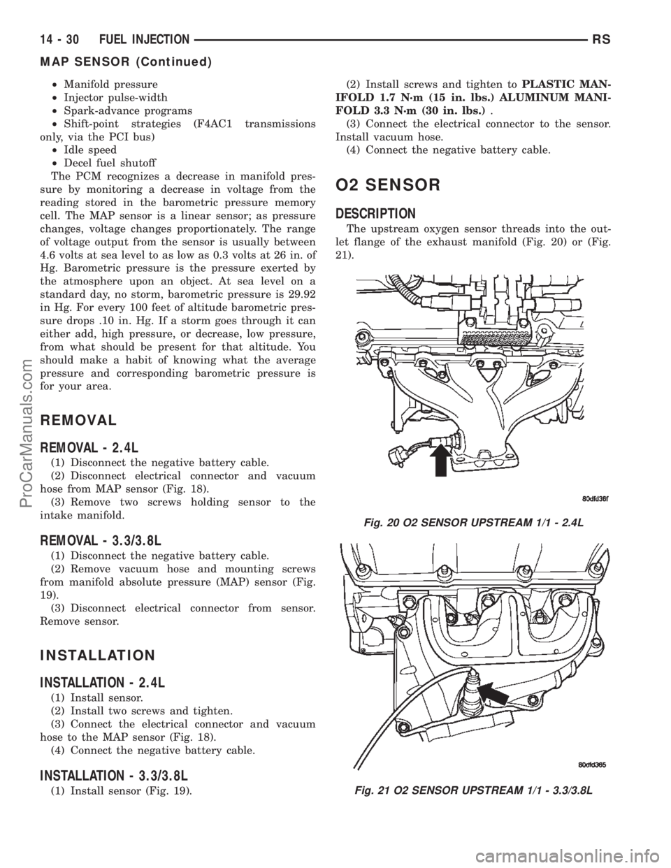
(2) Disconnect electrical connector and vacuum
hose from MAP sensor (Fig. 18).
(3) Remove two screws holding sensor to the
intake manifold.
REMOVAL - 3.3/3.8L
(1) Disconnect the negative battery cable.
(2) Remove vacuum hose and mounting screws
from manifold absolute pressure (MAP) sensor (Fig.
19).
(3) Disconnect electrical connector from sensor.
Remove sensor.
INSTALLATION
INSTALLATION - 2.4L
(1) Install sensor.
(2) Install two screws and tighten.
(3) Connect the electrical connector and vacuum
hose to the MAP sensor (Fig. 18).
(4) Connect the negative battery cable.
INSTALLATION - 3.3/3.8L
(1) Install sensor (Fig. 19).(2) Install screws and tighten toPLASTIC MAN-
IFOLD 1.7 N´m (15 in. lbs.) ALUMINUM MANI-
FOLD 3.3 N´m (30 in. lbs.).
(3) Connect the electrical connector to the sensor.
Install vacuum hose.
(4) Connect the negative battery cable.
O2 SENSOR
DESCRIPTION
The upstream oxygen sensor threads into the out-
let flange of the exhaust manifold (Fig. 20) or (Fig.
21).
Fig. 20 O2 SENSOR UPSTREAM 1/1 - 2.4L
Fig. 21 O2 SENSOR UPSTREAM 1/1 - 3.3/3.8L
14 - 30 FUEL INJECTIONRS
MAP SENSOR (Continued)
ProCarManuals.com
Page 1518 of 2399
IGNITION SWITCH
REMOVAL
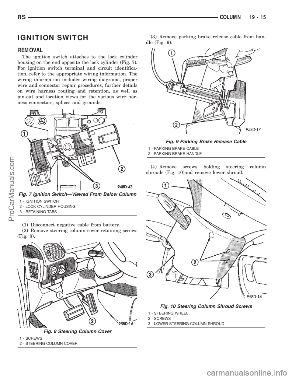
The ignition switch attaches to the lock cylinder
housing on the end opposite the lock cylinder (Fig. 7).
For ignition switch terminal and circuit identifica-
tion, refer to the appropriate wiring information. The
wiring information includes wiring diagrams, proper
wire and connector repair procedures, further details
on wire harness routing and retention, as well as
pin-out and location views for the various wire har-
ness connectors, splices and grounds.
(1) Disconnect negative cable from battery.
(2) Remove steering column cover retaining screws
(Fig. 8).(3) Remove parking brake release cable from han-
dle (Fig. 9).
(4) Remove screws holding steering column
shrouds (Fig. 10)and remove lower shroud.
Fig. 7 Ignition SwitchÐViewed From Below Column
1 - IGNITION SWITCH
2 - LOCK CYLINDER HOUSING
3 - RETAINING TABS
Fig. 8 Steering Column Cover
1 - SCREWS
2 - STEERING COLUMN COVER
Fig. 9 Parking Brake Release Cable
1 - PARKING BRAKE CABLE
2 - PARKING BRAKE HANDLE
Fig. 10 Steering Column Shroud Screws
1 - STEERING WHEEL
2 - SCREWS
3 - LOWER STEERING COLUMN SHROUD
RSCOLUMN19-15
ProCarManuals.com
Page 1520 of 2399
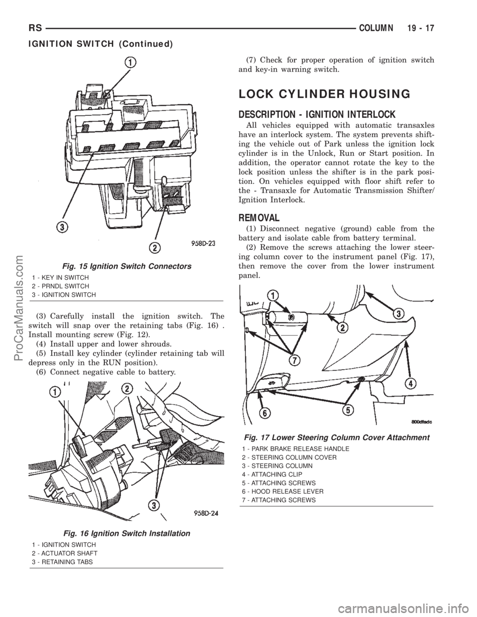
(3) Carefully install the ignition switch. The
switch will snap over the retaining tabs (Fig. 16) .
Install mounting screw (Fig. 12).
(4) Install upper and lower shrouds.
(5) Install key cylinder (cylinder retaining tab will
depress only in the RUN position).
(6) Connect negative cable to battery.(7) Check for proper operation of ignition switch
and key-in warning switch.
LOCK CYLINDER HOUSING
DESCRIPTION - IGNITION INTERLOCK
All vehicles equipped with automatic transaxles
have an interlock system. The system prevents shift-
ing the vehicle out of Park unless the ignition lock
cylinder is in the Unlock, Run or Start position. In
addition, the operator cannot rotate the key to the
lock position unless the shifter is in the park posi-
tion. On vehicles equipped with floor shift refer to
the - Transaxle for Automatic Transmission Shifter/
Ignition Interlock.
REMOVAL
(1) Disconnect negative (ground) cable from the
battery and isolate cable from battery terminal.
(2) Remove the screws attaching the lower steer-
ing column cover to the instrument panel (Fig. 17),
then remove the cover from the lower instrument
panel.
Fig. 15 Ignition Switch Connectors
1 - KEY IN SWITCH
2 - PRNDL SWITCH
3 - IGNITION SWITCH
Fig. 16 Ignition Switch Installation
1 - IGNITION SWITCH
2 - ACTUATOR SHAFT
3 - RETAINING TABS
Fig. 17 Lower Steering Column Cover Attachment
1 - PARK BRAKE RELEASE HANDLE
2 - STEERING COLUMN COVER
3 - STEERING COLUMN
4 - ATTACHING CLIP
5 - ATTACHING SCREWS
6 - HOOD RELEASE LEVER
7 - ATTACHING SCREWS
RSCOLUMN19-17
IGNITION SWITCH (Continued)
ProCarManuals.com
Page 1523 of 2399
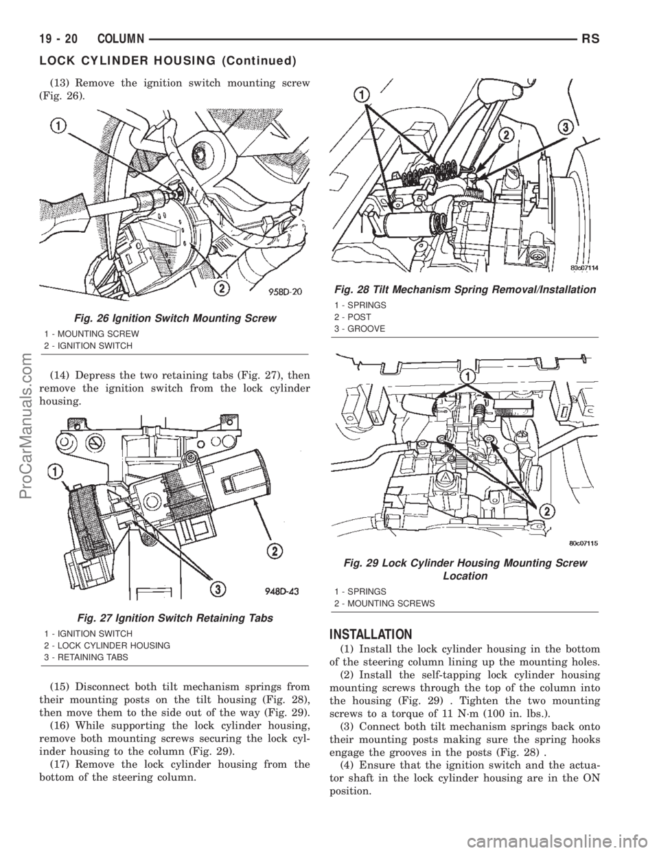
(13) Remove the ignition switch mounting screw
(Fig. 26).
(14) Depress the two retaining tabs (Fig. 27), then
remove the ignition switch from the lock cylinder
housing.
(15) Disconnect both tilt mechanism springs from
their mounting posts on the tilt housing (Fig. 28),
then move them to the side out of the way (Fig. 29).
(16) While supporting the lock cylinder housing,
remove both mounting screws securing the lock cyl-
inder housing to the column (Fig. 29).
(17) Remove the lock cylinder housing from the
bottom of the steering column.
INSTALLATION
(1) Install the lock cylinder housing in the bottom
of the steering column lining up the mounting holes.
(2) Install the self-tapping lock cylinder housing
mounting screws through the top of the column into
the housing (Fig. 29) . Tighten the two mounting
screws to a torque of 11 N´m (100 in. lbs.).
(3) Connect both tilt mechanism springs back onto
their mounting posts making sure the spring hooks
engage the grooves in the posts (Fig. 28) .
(4) Ensure that the ignition switch and the actua-
tor shaft in the lock cylinder housing are in the ON
position.
Fig. 26 Ignition Switch Mounting Screw
1 - MOUNTING SCREW
2 - IGNITION SWITCH
Fig. 27 Ignition Switch Retaining Tabs
1 - IGNITION SWITCH
2 - LOCK CYLINDER HOUSING
3 - RETAINING TABS
Fig. 28 Tilt Mechanism Spring Removal/Installation
1 - SPRINGS
2 - POST
3 - GROOVE
Fig. 29 Lock Cylinder Housing Mounting Screw
Location
1 - SPRINGS
2 - MOUNTING SCREWS
19 - 20 COLUMNRS
LOCK CYLINDER HOUSING (Continued)
ProCarManuals.com