2002 CHRYSLER CARAVAN seats
[x] Cancel search: seatsPage 2087 of 2399
INSTALLATION
(1) Place track in position on seat riser.
(2) Install nuts attaching track to seat riser. (Fig.
41). Tighten nuts to 48 N´m (35 ft. lbs.) torque.
(3) Engage seat track adjuster link wire onto track
being installed.
(4) Install second row seat into vehicle.
PLASTIC GROCERY BAG
RETAINER
REMOVAL
3-PASS BENCH SEAT
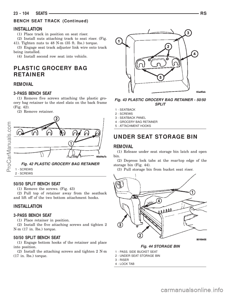
(1) Remove five screws attaching the plastic gro-
cery bag retainer to the steel slats on the back frame
(Fig. 42).
(2) Remove retainer.
50/50 SPLIT BENCH SEAT
(1) Remove the screws. (Fig. 43)
(2) Pull top of retainer away from the seatback
and lift off of the two bottom attachment hooks.
INSTALLATION
3-PASS BENCH SEAT
(1) Place retainer in position.
(2) Install the five attaching screws and tighten 2
N´m (17 in. lbs.) torque.
50/50 SPLIT BENCH SEAT
(1) Engage bottom hooks of the retainer and place
into position.
(2) Install the attaching screws and tighten 2 N´m
(17 in. lbs.) torque.
UNDER SEAT STORAGE BIN
REMOVAL
(1) Release under seat storage bin latch and open
bin.
(2) Depress lock tabs at the rear/top edge of the
storage bin (Fig. 44).
(3) Pull storage bin from bucket seat riser.
Fig. 42 PLASTIC GROCERY BAG RETAINER
1 - SCREWS
2 - SCREWS
Fig. 43 PLASTIC GROCERY BAG RETAINER - 50/50
SPLIT
1 - SEATBACK
2 - SCREWS
3 - SEATBACK PANEL
4 - GROCERY BAG RETAINER
5 - ATTACHMENT HOOKS
Fig. 44 STORAGE BIN
1 - PASS. SIDE BUCKET SEAT
2 - UNDER SEAT STORAGE BIN
3 - RISER
4 - LOCK TAB
23 - 104 SEATSRS
BENCH SEAT TRACK (Continued)
ProCarManuals.com
Page 2088 of 2399
INSTALLATION
(1) Engage storage bin tracks into guides on each
side of seat riser.
(2) Push storage bin inward until lock tabs snap
past retaining ridge on tracks
(3) Verify storage bin latch operation.
UNDER SEAT STORAGE BIN
GUIDE
REMOVAL
(1) Remove under seat storage bin. (Refer to 23 -
BODY/SEATS/UNDER SEAT STORAGE BIN -
REMOVAL)
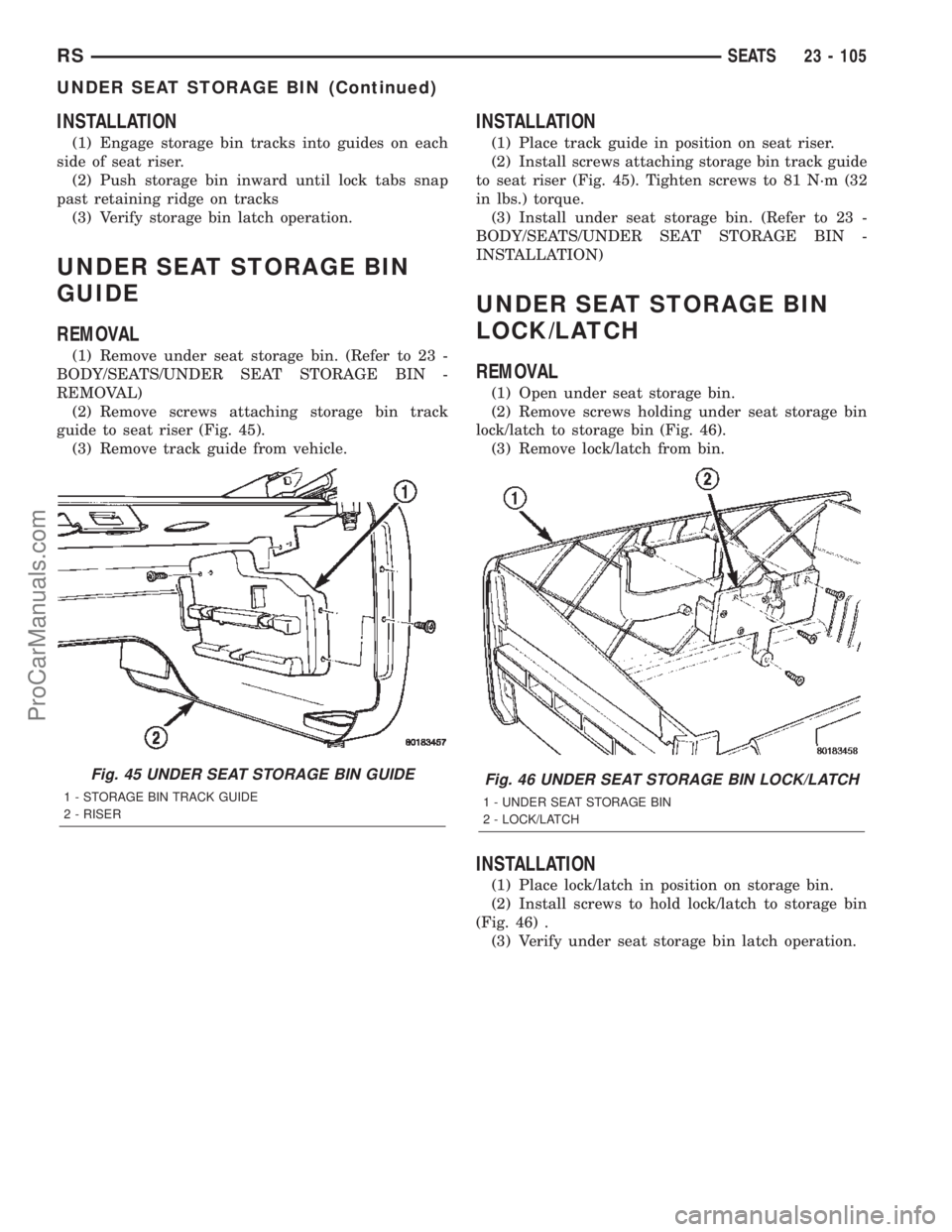
(2) Remove screws attaching storage bin track
guide to seat riser (Fig. 45).
(3) Remove track guide from vehicle.
INSTALLATION
(1) Place track guide in position on seat riser.
(2) Install screws attaching storage bin track guide
to seat riser (Fig. 45). Tighten screws to 81 N´m (32
in lbs.) torque.
(3) Install under seat storage bin. (Refer to 23 -
BODY/SEATS/UNDER SEAT STORAGE BIN -
INSTALLATION)
UNDER SEAT STORAGE BIN
LOCK/LATCH
REMOVAL
(1) Open under seat storage bin.
(2) Remove screws holding under seat storage bin
lock/latch to storage bin (Fig. 46).
(3) Remove lock/latch from bin.
INSTALLATION
(1) Place lock/latch in position on storage bin.
(2) Install screws to hold lock/latch to storage bin
(Fig. 46) .
(3) Verify under seat storage bin latch operation.
Fig. 45 UNDER SEAT STORAGE BIN GUIDE
1 - STORAGE BIN TRACK GUIDE
2 - RISER
Fig. 46 UNDER SEAT STORAGE BIN LOCK/LATCH
1 - UNDER SEAT STORAGE BIN
2 - LOCK/LATCH
RSSEATS23 - 105
UNDER SEAT STORAGE BIN (Continued)
ProCarManuals.com
Page 2089 of 2399
LUMBAR SUPPORT
REMOVAL
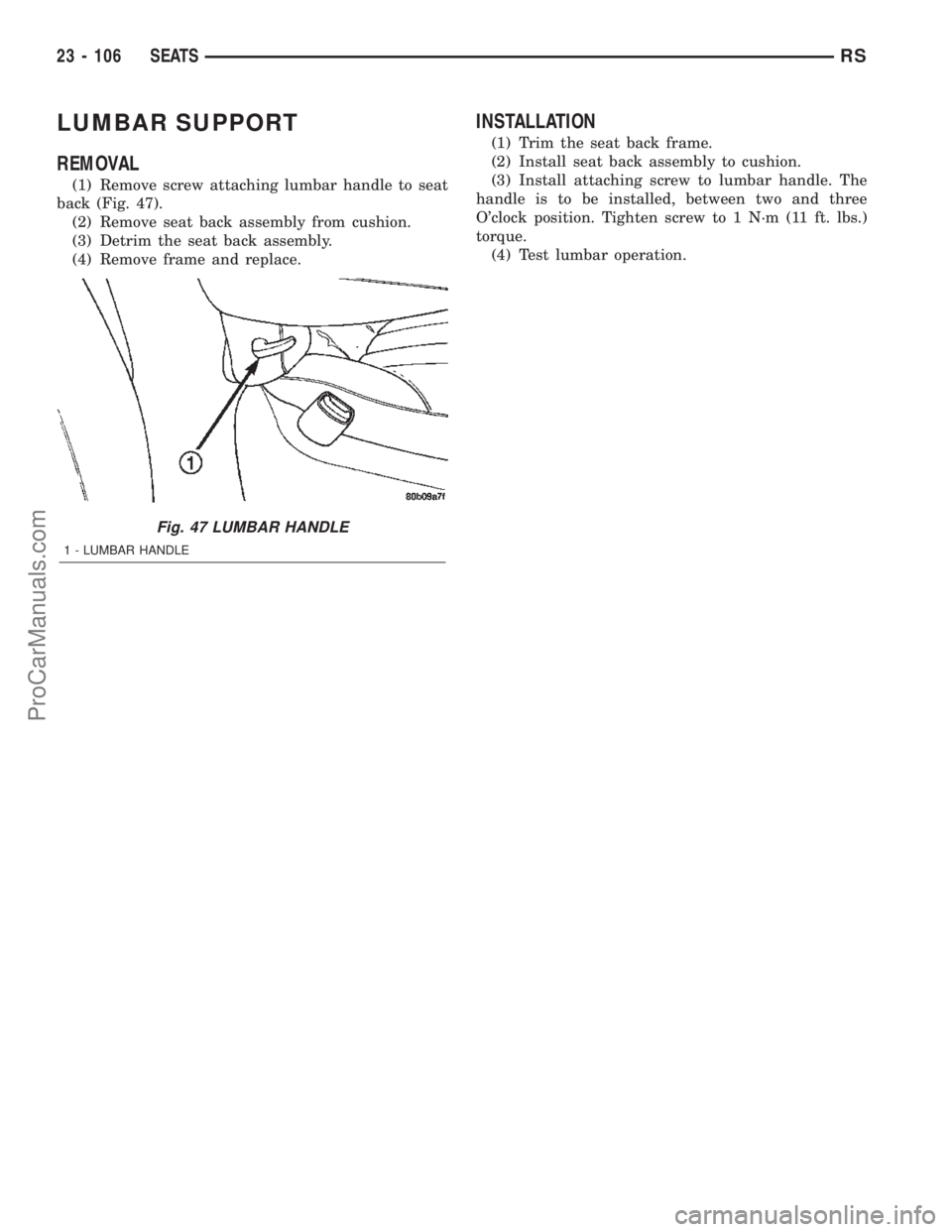
(1) Remove screw attaching lumbar handle to seat
back (Fig. 47).
(2) Remove seat back assembly from cushion.
(3) Detrim the seat back assembly.
(4) Remove frame and replace.
INSTALLATION
(1) Trim the seat back frame.
(2) Install seat back assembly to cushion.
(3) Install attaching screw to lumbar handle. The
handle is to be installed, between two and three
O'clock position. Tighten screw to 1 N´m (11 ft. lbs.)
torque.
(4) Test lumbar operation.
Fig. 47 LUMBAR HANDLE
1 - LUMBAR HANDLE
23 - 106 SEATSRS
ProCarManuals.com
Page 2294 of 2399
DISTRIBUTION - REAR
TABLE OF CONTENTS
page page
AIR OUTLETS
DESCRIPTION.........................51
REMOVAL.............................51
INSTALLATION.........................51
A/C DISTRIBUTION DUCT
REMOVAL.............................52
INSTALLATION.........................52
BLOWER MOTOR
DESCRIPTION.........................52
OPERATION...........................52DIAGNOSIS AND TESTING - BLOWER
MOTOR .............................53
REMOVAL.............................53
INSTALLATION.........................55
REAR HEATER-A/C HOUSING
REMOVAL.............................55
INSTALLATION.........................56
REAR HEATER DISTRIBUTION DUCT
REMOVAL.............................58
INSTALLATION.........................58
AIR OUTLETS
DESCRIPTION
Based upon the system mode selected, conditioned
air can exit the rear heater-A/C unit housing through
one or a combination of the two main housing out-
lets: air conditioner, or heater. Once the conditioned
air exits the unit housing, it is directed through
molded plastic ducts to the various outlets in the
vehicle interior. These outlets and their locations are
as follows:
²Floor Outlets- Three floor outlets with fixed
vanes are located in the right quarter trim panel,
near the floor. These outlets distribute air from the
rear heater distribution duct to the intermediate and
rear seat occupants. The floor outlets are integral to
the right quarter trim panel and, if faulty or dam-
aged, the quarter trim panel must be replaced.
²Overhead Outlets- Four (two right side and
two left side) fully adjustable outlets along the roof
rails distribute air from the rear A/C distribution
duct and the headliner ducts to the intermediate and
rear seat occupants. The headliner ducts are integral
to the headliner panel. Each overhead outlet is
housed in a headliner bezel. The two forward head-
liner bezels also feature a courtesy lamp, a fold-away
coat hook, and a fold-away assist handle. The over-
head outlets can be removed from the headliner
bezels individually for service replacement.
REMOVAL
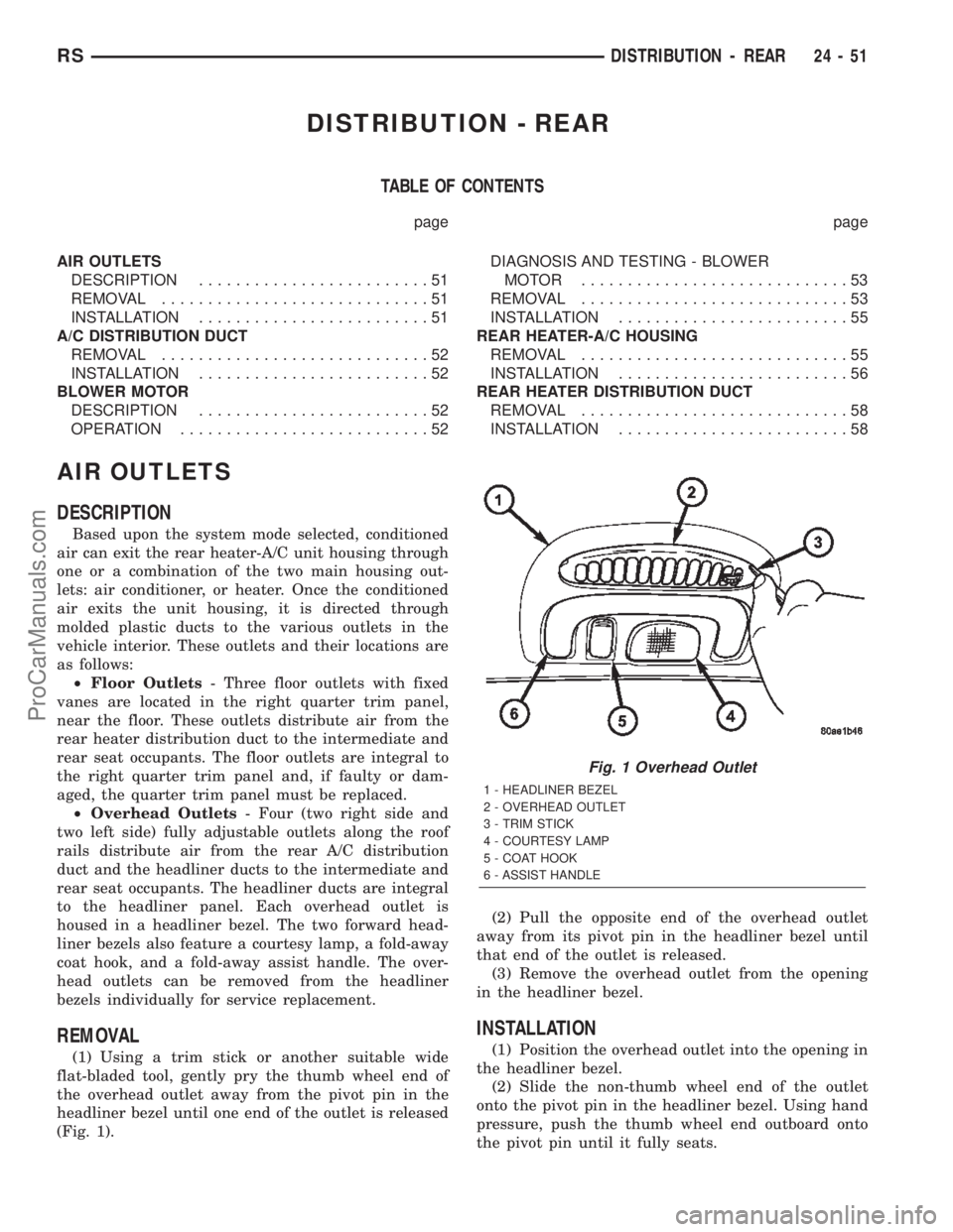
(1) Using a trim stick or another suitable wide
flat-bladed tool, gently pry the thumb wheel end of
the overhead outlet away from the pivot pin in the
headliner bezel until one end of the outlet is released
(Fig. 1).(2) Pull the opposite end of the overhead outlet
away from its pivot pin in the headliner bezel until
that end of the outlet is released.
(3) Remove the overhead outlet from the opening
in the headliner bezel.
INSTALLATION
(1) Position the overhead outlet into the opening in
the headliner bezel.
(2) Slide the non-thumb wheel end of the outlet
onto the pivot pin in the headliner bezel. Using hand
pressure, push the thumb wheel end outboard onto
the pivot pin until it fully seats.
Fig. 1 Overhead Outlet
1 - HEADLINER BEZEL
2 - OVERHEAD OUTLET
3 - TRIM STICK
4 - COURTESY LAMP
5 - COAT HOOK
6 - ASSIST HANDLE
RSDISTRIBUTION - REAR24-51
ProCarManuals.com
Page 2305 of 2399
CAUTION: All tools, including the refrigerant recy-
cling equipment, the manifold gauge set, and test
hoses should be kept clean and dry. Keep the work
area clean. Contamination of the refrigerant system
through careless work habits must be avoided. The
refrigerant system will remain chemically stable as
long as pure, moisture-free R-134a refrigerant and
refrigerant oil is used. Dirt, moisture, or air can
upset this chemical stability. Operational troubles
or serious damage can occur if foreign material is
introduced to the refrigerant system.
COMPRESSOR
DESCRIPTION
The compressor used on this vehicle can be one of
two models, depending upon the air conditioning sys-
tem in the vehicle. All vehicles use the Nippondenso
10S20 compressor. This compressor use an aluminum
swash plate, teflon coated pistons and aluminum
sleeveless cylinder walls. This compressor includes
an integral high pressure relief valve. The compres-
sor is secured low in the right front corner of the
engine compartment to a mounting bracket on the
cylinder block (2.4L engine), or directly to the cylin-
der block (3.3L and 3.8L engines) is integral to the
compressor. This compressor cannot be repaired. If
faulty or damaged, the entire compressor must be
replaced. The compressor clutch, pulley, and clutch
coil are available for service replacement.
OPERATION
The compressor is driven by the engine through an
electric clutch, drive pulley and belt arrangement.
The compressor is lubricated by refrigerant oil that is
circulated throughout the refrigerant system with the
refrigerant. The compressor draws in low-pressure
refrigerant vapor from the evaporator through its
suction port. It then compresses the refrigerant into
a high-pressure, high-temperature refrigerant vapor.
The compressor pumps high-pressure refrigerant
vapor to the condenser through the compressor dis-
charge port. The mechanical high pressure relief
valve is designed to vent refrigerant from the system
to protect against damage to the compressor or other
system components, caused by condenser air flow
restrictions or an overcharge of refrigerant. The valve
only vents enough refrigerant to reduce the system
pressure, then re-seats itself. The valve opens at a
discharge pressure of 3445 to 4135 kPA (500 to 600
psi) or above, and closes when a minimum discharge
pressure of 2756 kPa (400 psi) is reached.
DIAGNOSIS AND TESTING - COMPRESSOR
NOISE DIAGNOSIS
Excessive noise while the air conditioning compres-
sor is operating can be caused by loose compressor
mounts, a loose compressor clutch, or high operating
pressures in the refrigerant system. Verify compres-
sor drive belt condition, proper compressor mounting,
correct refrigerant charge level, and compressor head
pressure before compressor repair is performed.
With the close tolerances within the compressor, it
is possible to experience a temporary lockup. The
longer the compressor is inactive, the more likely the
condition is to occur. This condition is the result of
normal refrigerant migration within the refrigerant
system caused by ambient temperature changes. The
refrigerant migration may wash the refrigerant oil
out of the compressor.
NOTE: Prior to a vehicle being removed from ser-
vice or stored for more than two weeks, the com-
pressor should be operated to ensure adequate
refrigerant oil distribution throughout the system
components. Turn on the air conditioner for a min-
imum of five minutes with outside air and the high-
est blower speed selected.
BELT NOISE
If the compressor drive belt slips at initial start-up,
it does not necessarily mean the compressor has
failed. The following procedure can be used to iden-
tify a compressor drive belt noise problem.
²Start the vehicle and run at idle.
²Turn the air conditioner On and listen for belt
squeal.
²If belt squeal is heard, turn the air conditioner
Off immediately.
If the belt squeal stops when the air conditioner is
turned Off, perform the following repair procedures.
(1) Using an appropriate sized oil filter wrench or
a strap wrench, grasp the outer diameter of the com-
pressor clutch hub. While facing the compressor,
rotate the hub clockwise, then counterclockwise. If
the hub rotates, proceed to the next step. If the hub
will not rotate, the compressor is internally damaged,
and must be replaced.
(2) Turn the hub clockwise five complete revolu-
tions and remove the tool.
(3) Start the vehicle and run at idle.
(4) Turn the air conditioner On. Observe the com-
pressor and the system for normal operation, noting
cooling performance and noise levels. Operate for five
minutes before turning the air conditioner Off. If
acceptable cooling performance is observed during
compressor operation, the compressor does not need
to be replaced.
24 - 62 PLUMBING - FRONTRS
PLUMBING - FRONT (Continued)
ProCarManuals.com