2002 CHRYSLER CARAVAN fuel pump
[x] Cancel search: fuel pumpPage 1493 of 2399
Refer to the maintenance schedules for the recom-
mended fuel filter replacement intervals.
For draining of water from canister, refer to Fuel
Filter/Water Separator Removal/Installation section.
A Water-In-Fuel (WIF) sensor is part of the fuel fil-
ter cap. Refer to Water-In-Fuel Sensor Description/
Operation.
The fuel heater is installed into the filter/separator
housing above the fuel filter. Refer to Fuel Heater
Description/Operation.
FUEL LINES
DESCRIPTION
DESCRIPTION
All fuel lines up to the fuel injection pump are con-
sidered low-pressure. This includes the fuel lines
from: the fuel tank to the fuel transfer pump, and
the fuel transfer pump to the fuel injection pump.
The fuel return lines and the fuel drain lines are also
considered low-pressure lines. High-pressure lines
are used between the fuel injection pump and the
fuel injectors. Also refer to High-Pressure Fuel Lines
Description/Operation.
DESCRIPTION - HIGH PRESSURE FUEL LINES
The high-pressure fuel lines are the 4 lines located
between the fuel injection pump and the fuel injec-
torsctor tubes. All other fuel lines are considered low-
pressure lines.
OPERATION - HIGH PRESSURE FUEL LINES
CAUTION: The high-pressure fuel lines cannot con-
tact each other or other components. Do not
attempt to weld high-pressure fuel lines or to repair
lines that are damaged. If lines are ever kinked or
bent, they must be replaced. Use only the recom-
mended lines when replacement of high-pressure
fuel line is necessary.
High-pressure fuel lines deliver fuel under
extremely high pressure from the injection pump to
the fuel injectors. The lines expand and contract from
the high-pressure fuel pulses generated during the
injection process. All high-pressure fuel lines are of
the same length and inside diameter. Correct high-
pressure fuel line usage and installation is critical to
smooth engine operation.
WARNING: USE EXTREME CAUTION WHEN
INSPECTING FOR HIGH-PRESSURE FUEL LEAKS.
INSPECT FOR HIGH-PRESSURE FUEL LEAKS WITH
A SHEET OF CARDBOARD. HIGH FUEL INJECTIONPRESSURE CAN CAUSE PERSONAL INJURY IF
CONTACT IS MADE WITH THE SKIN.
DIAGNOSIS AND TESTING - HIGH PRESSURE
FUEL LINES
High-pressure fuel line leaks can cause starting
problems and poor engine performance.
WARNING: DUE TO EXTREME FUEL PRESSURES,
USE EXTREME CAUTION WHEN INSPECTING FOR
HIGH-PRESSURE FUEL LEAKS. DO NOT GET YOUR
HAND NEAR A SUSPECTED LEAK. INSPECT FOR
HIGH-PRESSURE FUEL LEAKS WITH A SHEET OF
CARDBOARD. HIGH FUEL INJECTION PRESSURE
CAN CAUSE PERSONAL INJURY IF CONTACT IS
MADE WITH THE SKIN.
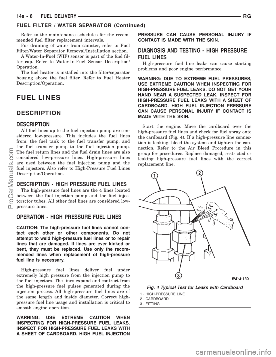
Start the engine. Move the cardboard over the
high-pressure fuel lines and check for fuel spray onto
the cardboard (Fig. 4). If a high-pressure line connec-
tion is leaking, bleed the system and tighten the con-
nection. Refer to the Air Bleed Procedure in this
group for procedures. Replace damaged, restricted or
leaking high-pressure fuel lines with the correct
replacement line.
Fig. 4 Typical Test for Leaks with Cardboard
1 - HIGH-PRESSURE LINE
2 - CARDBOARD
3 - FITTING
14a - 6 FUEL DELIVERYRG
FUEL FILTER / WATER SEPARATOR (Continued)
ProCarManuals.com
Page 1494 of 2399
CAUTION: The high-pressure fuel lines cannot con-
tact each other or other components. Do not
attempt to weld high-pressure fuel lines or to repair
lines that are damaged. Only use the recommended
lines when replacement of high-pressure fuel line is
necessary.
FUEL TRANSFER PUMP
DESCRIPTION
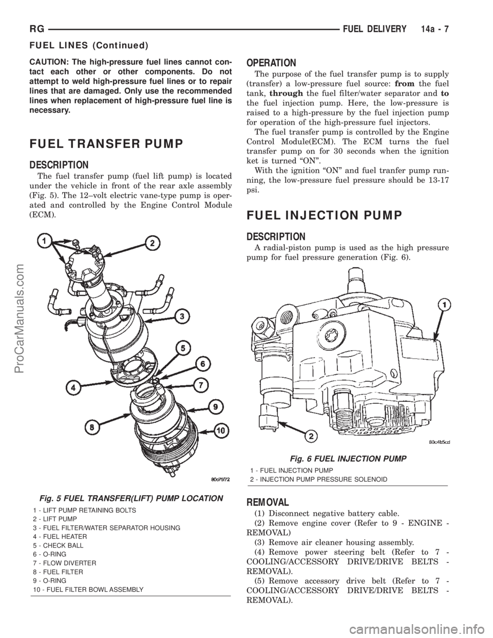
The fuel transfer pump (fuel lift pump) is located
under the vehicle in front of the rear axle assembly
(Fig. 5). The 12±volt electric vane-type pump is oper-
ated and controlled by the Engine Control Module
(ECM).
OPERATION
The purpose of the fuel transfer pump is to supply
(transfer) a low-pressure fuel source:fromthe fuel
tank,throughthe fuel filter/water separator andto
the fuel injection pump. Here, the low-pressure is
raised to a high-pressure by the fuel injection pump
for operation of the high-pressure fuel injectors.
The fuel transfer pump is controlled by the Engine
Control Module(ECM). The ECM turns the fuel
transfer pump on for 30 seconds when the ignition
ket is turned ªONº.
With the ignition ªONº and fuel tranfer pump run-
ning, the low-pressure fuel pressure should be 13-17
psi.
FUEL INJECTION PUMP
DESCRIPTION
A radial-piston pump is used as the high pressure
pump for fuel pressure generation (Fig. 6).
REMOVAL
(1) Disconnect negative battery cable.
(2) Remove engine cover (Refer to 9 - ENGINE -
REMOVAL)
(3) Remove air cleaner housing assembly.
(4) Remove power steering belt (Refer to 7 -
COOLING/ACCESSORY DRIVE/DRIVE BELTS -
REMOVAL).
(5) Remove accessory drive belt (Refer to 7 -
COOLING/ACCESSORY DRIVE/DRIVE BELTS -
REMOVAL).
Fig. 5 FUEL TRANSFER(LIFT) PUMP LOCATION
1 - LIFT PUMP RETAINING BOLTS
2 - LIFT PUMP
3 - FUEL FILTER/WATER SEPARATOR HOUSING
4 - FUEL HEATER
5 - CHECK BALL
6 - O-RING
7 - FLOW DIVERTER
8 - FUEL FILTER
9 - O-RING
10 - FUEL FILTER BOWL ASSEMBLY
Fig. 6 FUEL INJECTION PUMP
1 - FUEL INJECTION PUMP
2 - INJECTION PUMP PRESSURE SOLENOID
RGFUEL DELIVERY14a-7
FUEL LINES (Continued)
ProCarManuals.com
Page 1495 of 2399
(6) Support engine and remove right engine mount
assembly.
(7) Remove outer timing belt cover (Refer to 9 -
ENGINE/VALVE TIMING/TIMING BELT / CHAIN
COVER(S) - REMOVAL).
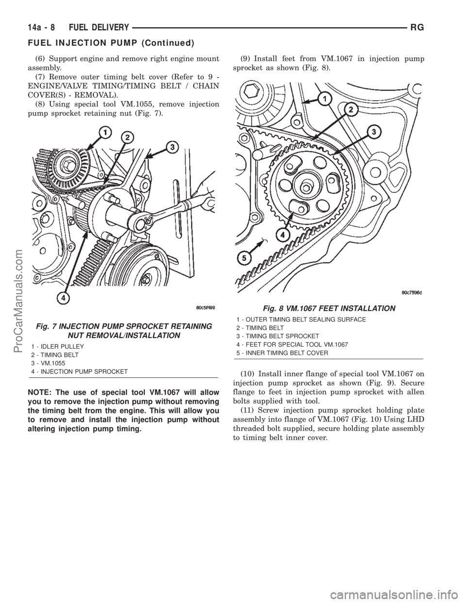
(8) Using special tool VM.1055, remove injection
pump sprocket retaining nut (Fig. 7).
NOTE: The use of special tool VM.1067 will allow
you to remove the injection pump without removing
the timing belt from the engine. This will allow you
to remove and install the injection pump without
altering injection pump timing.(9) Install feet from VM.1067 in injection pump
sprocket as shown (Fig. 8).
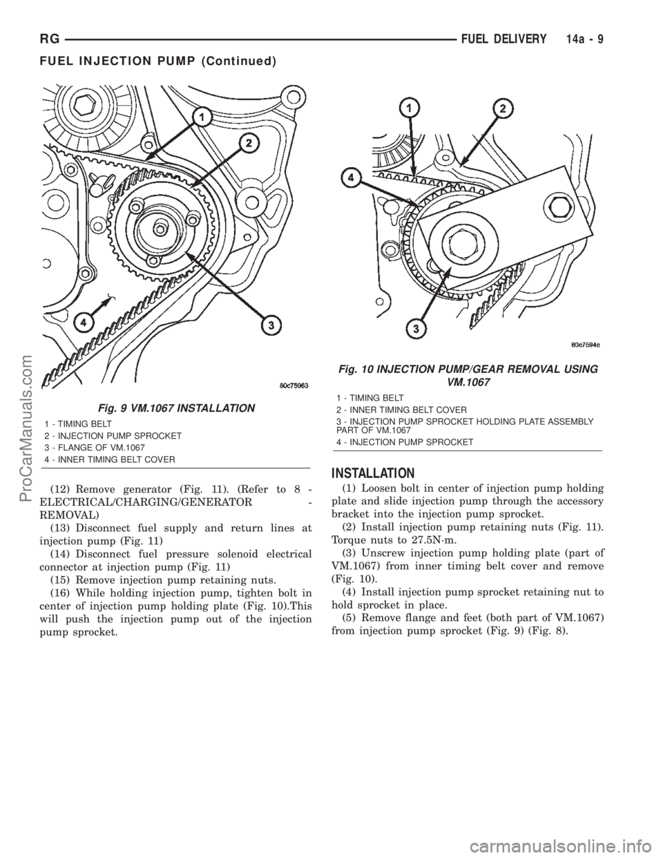
(10) Install inner flange of special tool VM.1067 on
injection pump sprocket as shown (Fig. 9). Secure
flange to feet in injection pump sprocket with allen
bolts supplied with tool.
(11) Screw injection pump sprocket holding plate
assembly into flange of VM.1067 (Fig. 10) Using LHD
threaded bolt supplied, secure holding plate assembly
to timing belt inner cover.
Fig. 7 INJECTION PUMP SPROCKET RETAINING
NUT REMOVAL/INSTALLATION
1 - IDLER PULLEY
2 - TIMING BELT
3 - VM.1055
4 - INJECTION PUMP SPROCKET
Fig. 8 VM.1067 FEET INSTALLATION
1 - OUTER TIMING BELT SEALING SURFACE
2 - TIMING BELT
3 - TIMING BELT SPROCKET
4 - FEET FOR SPECIAL TOOL VM.1067
5 - INNER TIMING BELT COVER
14a - 8 FUEL DELIVERYRG
FUEL INJECTION PUMP (Continued)
ProCarManuals.com
Page 1496 of 2399
(12) Remove generator (Fig. 11). (Refer to 8 -
ELECTRICAL/CHARGING/GENERATOR -
REMOVAL)
(13) Disconnect fuel supply and return lines at
injection pump (Fig. 11)
(14) Disconnect fuel pressure solenoid electrical
connector at injection pump (Fig. 11)
(15) Remove injection pump retaining nuts.
(16) While holding injection pump, tighten bolt in
center of injection pump holding plate (Fig. 10).This
will push the injection pump out of the injection
pump sprocket.
INSTALLATION
(1) Loosen bolt in center of injection pump holding
plate and slide injection pump through the accessory
bracket into the injection pump sprocket.
(2) Install injection pump retaining nuts (Fig. 11).
Torque nuts to 27.5N´m.
(3) Unscrew injection pump holding plate (part of
VM.1067) from inner timing belt cover and remove
(Fig. 10).
(4) Install injection pump sprocket retaining nut to
hold sprocket in place.
(5) Remove flange and feet (both part of VM.1067)
from injection pump sprocket (Fig. 9) (Fig. 8).
Fig. 9 VM.1067 INSTALLATION
1 - TIMING BELT
2 - INJECTION PUMP SPROCKET
3 - FLANGE OF VM.1067
4 - INNER TIMING BELT COVER
Fig. 10 INJECTION PUMP/GEAR REMOVAL USING
VM.1067
1 - TIMING BELT
2 - INNER TIMING BELT COVER
3 - INJECTION PUMP SPROCKET HOLDING PLATE ASSEMBLY
PART OF VM.1067
4 - INJECTION PUMP SPROCKET
RGFUEL DELIVERY14a-9
FUEL INJECTION PUMP (Continued)
ProCarManuals.com
Page 1497 of 2399
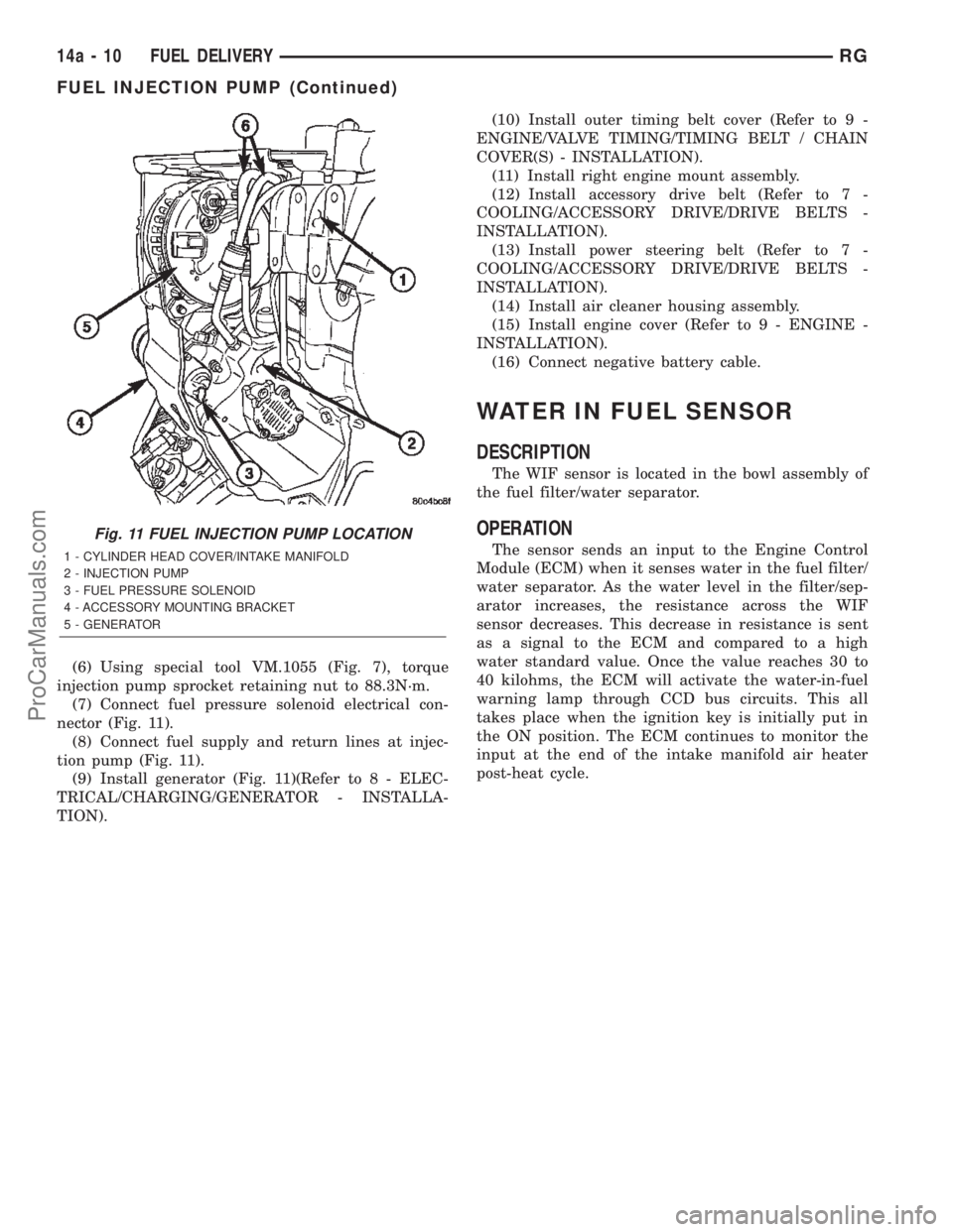
(6) Using special tool VM.1055 (Fig. 7), torque
injection pump sprocket retaining nut to 88.3N´m.
(7) Connect fuel pressure solenoid electrical con-
nector (Fig. 11).
(8) Connect fuel supply and return lines at injec-
tion pump (Fig. 11).
(9) Install generator (Fig. 11)(Refer to 8 - ELEC-
TRICAL/CHARGING/GENERATOR - INSTALLA-
TION).(10) Install outer timing belt cover (Refer to 9 -
ENGINE/VALVE TIMING/TIMING BELT / CHAIN
COVER(S) - INSTALLATION).
(11) Install right engine mount assembly.
(12) Install accessory drive belt (Refer to 7 -
COOLING/ACCESSORY DRIVE/DRIVE BELTS -
INSTALLATION).
(13) Install power steering belt (Refer to 7 -
COOLING/ACCESSORY DRIVE/DRIVE BELTS -
INSTALLATION).
(14) Install air cleaner housing assembly.
(15) Install engine cover (Refer to 9 - ENGINE -
INSTALLATION).
(16) Connect negative battery cable.
WATER IN FUEL SENSOR
DESCRIPTION
The WIF sensor is located in the bowl assembly of
the fuel filter/water separator.
OPERATION
The sensor sends an input to the Engine Control
Module (ECM) when it senses water in the fuel filter/
water separator. As the water level in the filter/sep-
arator increases, the resistance across the WIF
sensor decreases. This decrease in resistance is sent
as a signal to the ECM and compared to a high
water standard value. Once the value reaches 30 to
40 kilohms, the ECM will activate the water-in-fuel
warning lamp through CCD bus circuits. This all
takes place when the ignition key is initially put in
the ON position. The ECM continues to monitor the
input at the end of the intake manifold air heater
post-heat cycle.
Fig. 11 FUEL INJECTION PUMP LOCATION
1 - CYLINDER HEAD COVER/INTAKE MANIFOLD
2 - INJECTION PUMP
3 - FUEL PRESSURE SOLENOID
4 - ACCESSORY MOUNTING BRACKET
5 - GENERATOR
14a - 10 FUEL DELIVERYRG
FUEL INJECTION PUMP (Continued)
ProCarManuals.com
Page 1498 of 2399
FUEL INJECTION
TABLE OF CONTENTS
page page
FUEL INJECTOR
DESCRIPTION
FUEL INJECTOR......................11
OPERATION...........................11
REMOVAL.............................12
INSTALLATION.........................13
ACCELERATOR PEDAL POSITION SENSOR
DESCRIPTION.........................13
OPERATION...........................13
REMOVAL
REMOVAL - PEDAL POSITION SENSOR
(LHD)...............................14
REMOVAL - PEDAL POSITION SENSOR
(RHD)..............................14
INSTALLATION
INSTALLATION - PEDAL POSITION SENSOR
(LHD)...............................14
INSTALLATION - PEDAL POSITION SENSOR
(RHD)..............................14BOOST PRESSURE SENSOR
DESCRIPTION.........................14
OPERATION...........................14
DIAGNOSIS AND TESTING - BOOST
PRESSURE/INTAKE AIR TEMPERATURE
SENSOR............................14
INTAKE AIR TEMPERATURE SENSOR
DESCRIPTION.........................15
OPERATION...........................15
REMOVAL.............................15
INSTALLATION.........................15
CRANKSHAFT POSITION SENSOR
DESCRIPTION.........................15
OPERATION...........................15
MASS AIR FLOW (MAF) SENSOR
DESCRIPTION.........................16
OPERATION...........................16
REMOVAL.............................16
INSTALLATION.........................16
FUEL INJECTOR
DESCRIPTION
FUEL INJECTOR
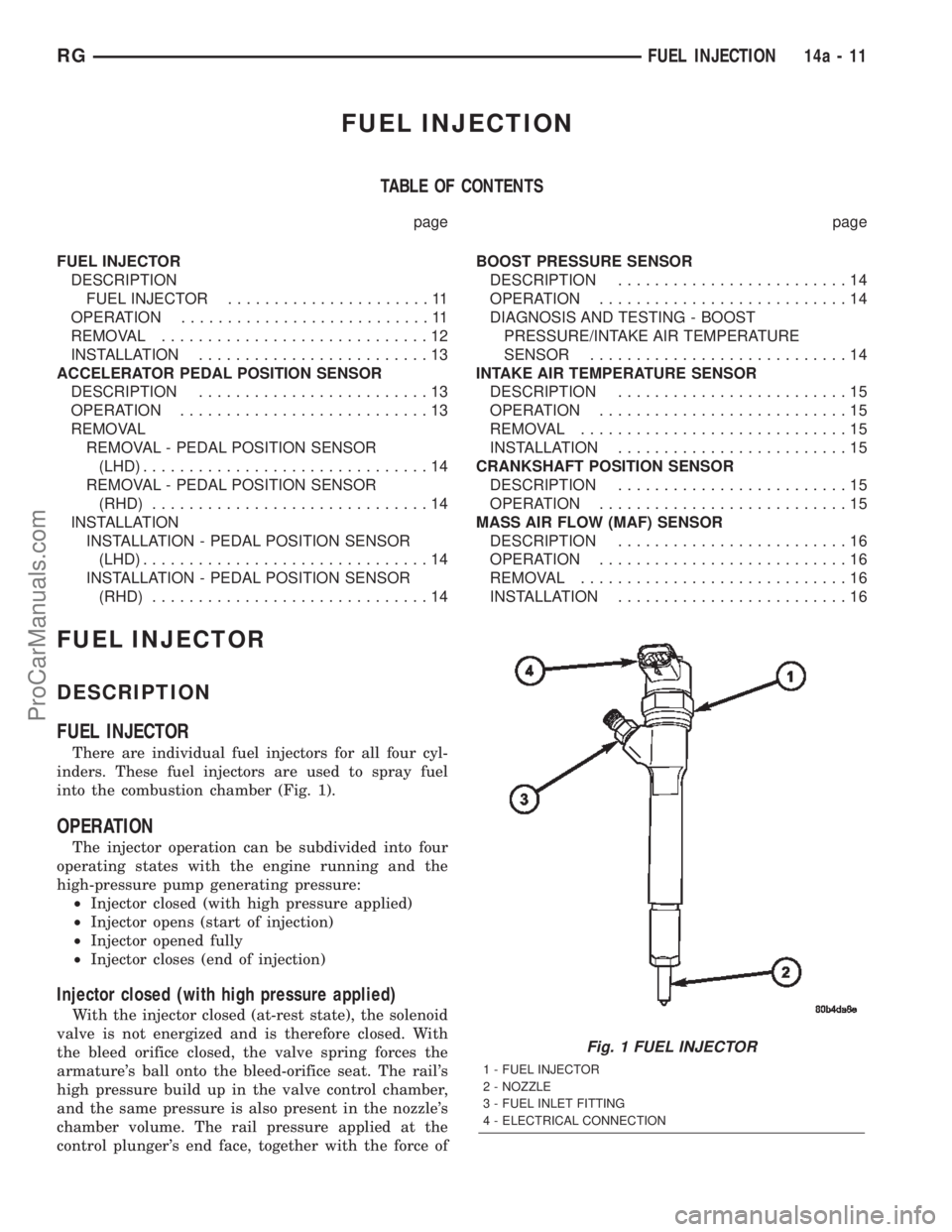
There are individual fuel injectors for all four cyl-
inders. These fuel injectors are used to spray fuel
into the combustion chamber (Fig. 1).
OPERATION
The injector operation can be subdivided into four
operating states with the engine running and the
high-pressure pump generating pressure:
²Injector closed (with high pressure applied)
²Injector opens (start of injection)
²Injector opened fully
²Injector closes (end of injection)
Injector closed (with high pressure applied)
With the injector closed (at-rest state), the solenoid
valve is not energized and is therefore closed. With
the bleed orifice closed, the valve spring forces the
armature's ball onto the bleed-orifice seat. The rail's
high pressure build up in the valve control chamber,
and the same pressure is also present in the nozzle's
chamber volume. The rail pressure applied at the
control plunger's end face, together with the force of
Fig. 1 FUEL INJECTOR
1 - FUEL INJECTOR
2 - NOZZLE
3 - FUEL INLET FITTING
4 - ELECTRICAL CONNECTION
RGFUEL INJECTION14a-11
ProCarManuals.com
Page 1679 of 2399
ADJUSTMENTS
THROTTLE VALVE LINKAGE ADJUSTMENT
The throttle valve linkage adjustment is very
important to proper transaxle operation. This adjust-
ment positions a valve which controls shift speed,
shift quality, and part throttle downshift sensitivity.
If the setting is too short, early shifts and slippage
between shifts may occur. If the setting is too long,
shifts may be delayed and part throttle downshifts
may be very sensitive.
LINKAGE ADJUSTMENT PROCEDURE
(1) Perform transaxle throttle valve linkage
adjustment while engine is at normal operating tem-
perature.
(2) Using small screwdriver, disengage adjustment
lock at transaxle.
(3) Rotate lever at transaxle all the way to the left
side of vehicle against stop.
(4) Slide cable adjuster until cable core end
touches clip at throttle valve lever.
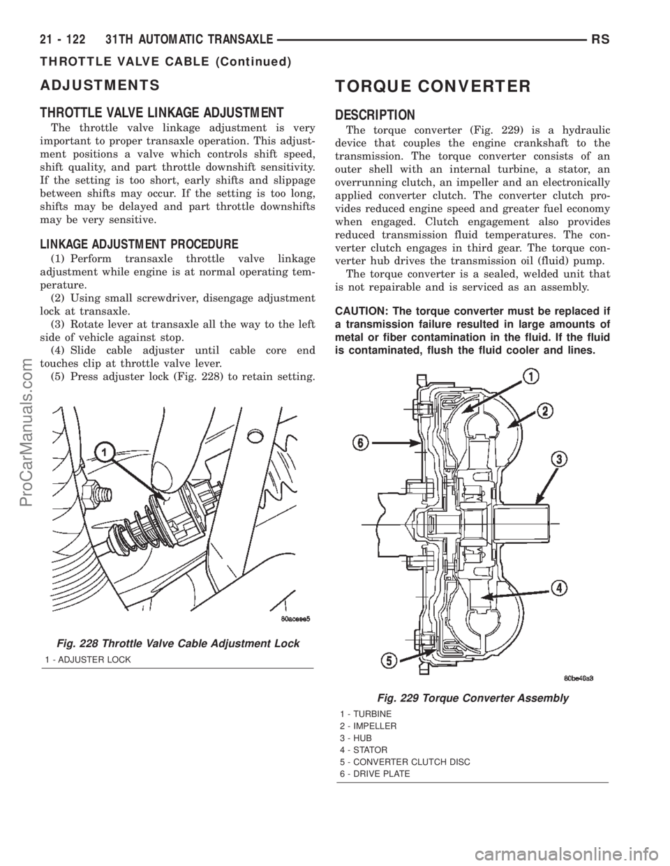
(5) Press adjuster lock (Fig. 228) to retain setting.
TORQUE CONVERTER
DESCRIPTION
The torque converter (Fig. 229) is a hydraulic
device that couples the engine crankshaft to the
transmission. The torque converter consists of an
outer shell with an internal turbine, a stator, an
overrunning clutch, an impeller and an electronically
applied converter clutch. The converter clutch pro-
vides reduced engine speed and greater fuel economy
when engaged. Clutch engagement also provides
reduced transmission fluid temperatures. The con-
verter clutch engages in third gear. The torque con-
verter hub drives the transmission oil (fluid) pump.
The torque converter is a sealed, welded unit that
is not repairable and is serviced as an assembly.
CAUTION: The torque converter must be replaced if
a transmission failure resulted in large amounts of
metal or fiber contamination in the fluid. If the fluid
is contaminated, flush the fluid cooler and lines.
Fig. 228 Throttle Valve Cable Adjustment Lock
1 - ADJUSTER LOCK
Fig. 229 Torque Converter Assembly
1 - TURBINE
2 - IMPELLER
3 - HUB
4-STATOR
5 - CONVERTER CLUTCH DISC
6 - DRIVE PLATE
21 - 122 31TH AUTOMATIC TRANSAXLERS
THROTTLE VALVE CABLE (Continued)
ProCarManuals.com
Page 1842 of 2399
TORQUE CONVERTER
DESCRIPTION
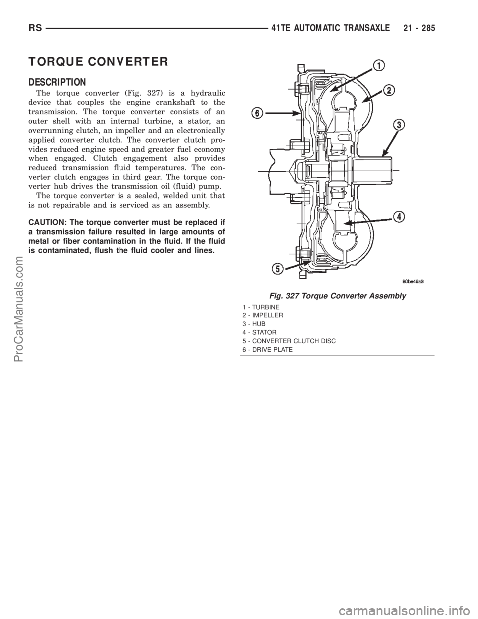
The torque converter (Fig. 327) is a hydraulic
device that couples the engine crankshaft to the
transmission. The torque converter consists of an
outer shell with an internal turbine, a stator, an
overrunning clutch, an impeller and an electronically
applied converter clutch. The converter clutch pro-
vides reduced engine speed and greater fuel economy
when engaged. Clutch engagement also provides
reduced transmission fluid temperatures. The con-
verter clutch engages in third gear. The torque con-
verter hub drives the transmission oil (fluid) pump.
The torque converter is a sealed, welded unit that
is not repairable and is serviced as an assembly.
CAUTION: The torque converter must be replaced if
a transmission failure resulted in large amounts of
metal or fiber contamination in the fluid. If the fluid
is contaminated, flush the fluid cooler and lines.
Fig. 327 Torque Converter Assembly
1 - TURBINE
2 - IMPELLER
3 - HUB
4-STATOR
5 - CONVERTER CLUTCH DISC
6 - DRIVE PLATE
RS41TE AUTOMATIC TRANSAXLE21 - 285
ProCarManuals.com