2002 CHRYSLER CARAVAN airbag
[x] Cancel search: airbagPage 1153 of 2399
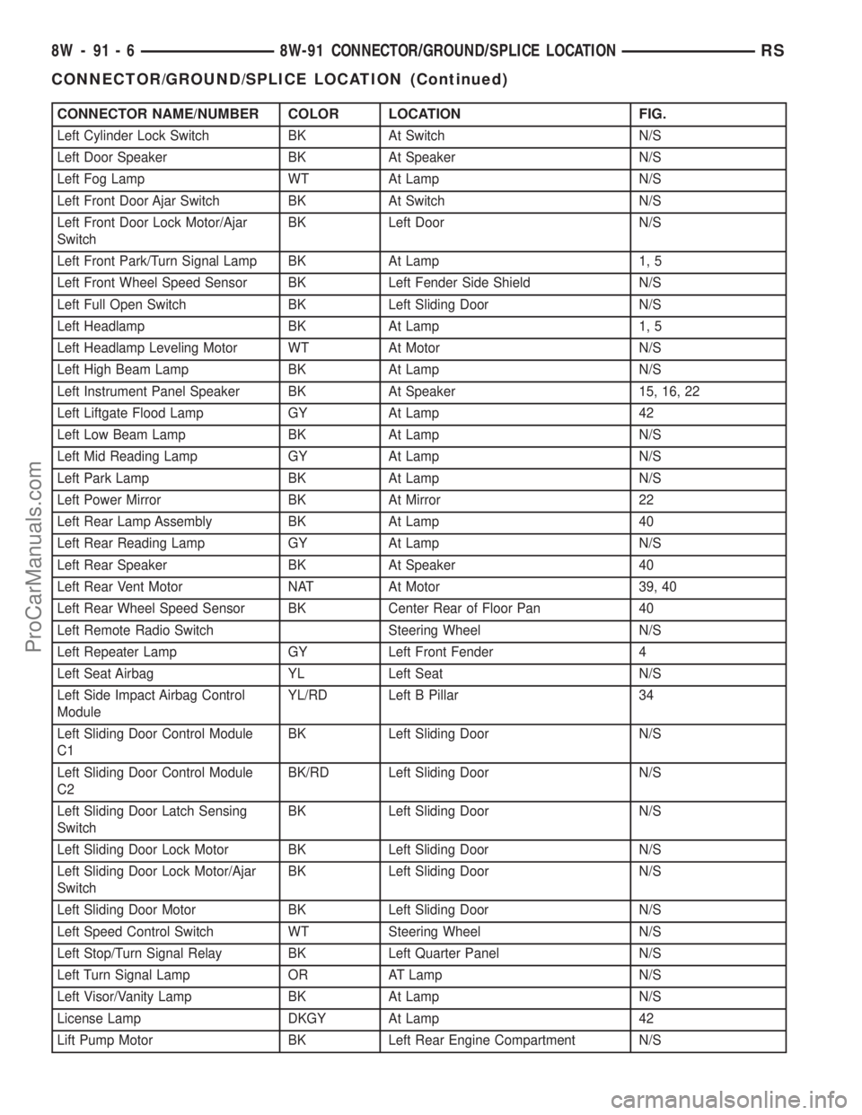
CONNECTOR NAME/NUMBER COLOR LOCATION FIG.
Left Cylinder Lock Switch BK At Switch N/S
Left Door Speaker BK At Speaker N/S
Left Fog Lamp WT At Lamp N/S
Left Front Door Ajar Switch BK At Switch N/S
Left Front Door Lock Motor/Ajar
SwitchBK Left Door N/S
Left Front Park/Turn Signal Lamp BK At Lamp 1, 5
Left Front Wheel Speed Sensor BK Left Fender Side Shield N/S
Left Full Open Switch BK Left Sliding Door N/S
Left Headlamp BK At Lamp 1, 5
Left Headlamp Leveling Motor WT At Motor N/S
Left High Beam Lamp BK At Lamp N/S
Left Instrument Panel Speaker BK At Speaker 15, 16, 22
Left Liftgate Flood Lamp GY At Lamp 42
Left Low Beam Lamp BK At Lamp N/S
Left Mid Reading Lamp GY At Lamp N/S
Left Park Lamp BK At Lamp N/S
Left Power Mirror BK At Mirror 22
Left Rear Lamp Assembly BK At Lamp 40
Left Rear Reading Lamp GY At Lamp N/S
Left Rear Speaker BK At Speaker 40
Left Rear Vent Motor NAT At Motor 39, 40
Left Rear Wheel Speed Sensor BK Center Rear of Floor Pan 40
Left Remote Radio Switch Steering Wheel N/S
Left Repeater Lamp GY Left Front Fender 4
Left Seat Airbag YL Left Seat N/S
Left Side Impact Airbag Control
ModuleYL/RD Left B Pillar 34
Left Sliding Door Control Module
C1BK Left Sliding Door N/S
Left Sliding Door Control Module
C2BK/RD Left Sliding Door N/S
Left Sliding Door Latch Sensing
SwitchBK Left Sliding Door N/S
Left Sliding Door Lock Motor BK Left Sliding Door N/S
Left Sliding Door Lock Motor/Ajar
SwitchBK Left Sliding Door N/S
Left Sliding Door Motor BK Left Sliding Door N/S
Left Speed Control Switch WT Steering Wheel N/S
Left Stop/Turn Signal Relay BK Left Quarter Panel N/S
Left Turn Signal Lamp OR AT Lamp N/S
Left Visor/Vanity Lamp BK At Lamp N/S
License Lamp DKGY At Lamp 42
Lift Pump Motor BK Left Rear Engine Compartment N/S
8W - 91 - 6 8W-91 CONNECTOR/GROUND/SPLICE LOCATIONRS
CONNECTOR/GROUND/SPLICE LOCATION (Continued)
ProCarManuals.com
Page 1154 of 2399
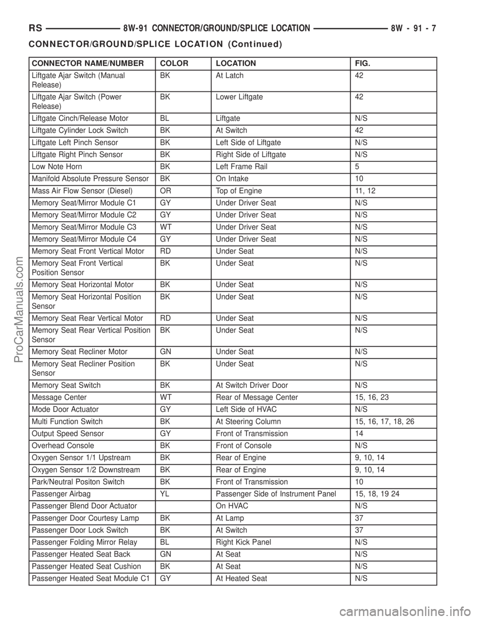
CONNECTOR NAME/NUMBER COLOR LOCATION FIG.
Liftgate Ajar Switch (Manual
Release)BK At Latch 42
Liftgate Ajar Switch (Power
Release)BK Lower Liftgate 42
Liftgate Cinch/Release Motor BL Liftgate N/S
Liftgate Cylinder Lock Switch BK At Switch 42
Liftgate Left Pinch Sensor BK Left Side of Liftgate N/S
Liftgate Right Pinch Sensor BK Right Side of Liftgate N/S
Low Note Horn BK Left Frame Rail 5
Manifold Absolute Pressure Sensor BK On Intake 10
Mass Air Flow Sensor (Diesel) OR Top of Engine 11, 12
Memory Seat/Mirror Module C1 GY Under Driver Seat N/S
Memory Seat/Mirror Module C2 GY Under Driver Seat N/S
Memory Seat/Mirror Module C3 WT Under Driver Seat N/S
Memory Seat/Mirror Module C4 GY Under Driver Seat N/S
Memory Seat Front Vertical Motor RD Under Seat N/S
Memory Seat Front Vertical
Position SensorBK Under Seat N/S
Memory Seat Horizontal Motor BK Under Seat N/S
Memory Seat Horizontal Position
SensorBK Under Seat N/S
Memory Seat Rear Vertical Motor RD Under Seat N/S
Memory Seat Rear Vertical Position
SensorBK Under Seat N/S
Memory Seat Recliner Motor GN Under Seat N/S
Memory Seat Recliner Position
SensorBK Under Seat N/S
Memory Seat Switch BK At Switch Driver Door N/S
Message Center WT Rear of Message Center 15, 16, 23
Mode Door Actuator GY Left Side of HVAC N/S
Multi Function Switch BK At Steering Column 15, 16, 17, 18, 26
Output Speed Sensor GY Front of Transmission 14
Overhead Console BK Front of Console N/S
Oxygen Sensor 1/1 Upstream BK Rear of Engine 9, 10, 14
Oxygen Sensor 1/2 Downstream BK Rear of Engine 9, 10, 14
Park/Neutral Positon Switch BK Front of Transmission 10
Passenger Airbag YL Passenger Side of Instrument Panel 15, 18, 19 24
Passenger Blend Door Actuator On HVAC N/S
Passenger Door Courtesy Lamp BK At Lamp 37
Passenger Door Lock Switch BK At Switch 37
Passenger Folding Mirror Relay BL Right Kick Panel N/S
Passenger Heated Seat Back GN At Seat N/S
Passenger Heated Seat Cushion BK At Seat N/S
Passenger Heated Seat Module C1 GY At Heated Seat N/S
RS8W-91 CONNECTOR/GROUND/SPLICE LOCATION8W-91-7
CONNECTOR/GROUND/SPLICE LOCATION (Continued)
ProCarManuals.com
Page 1157 of 2399
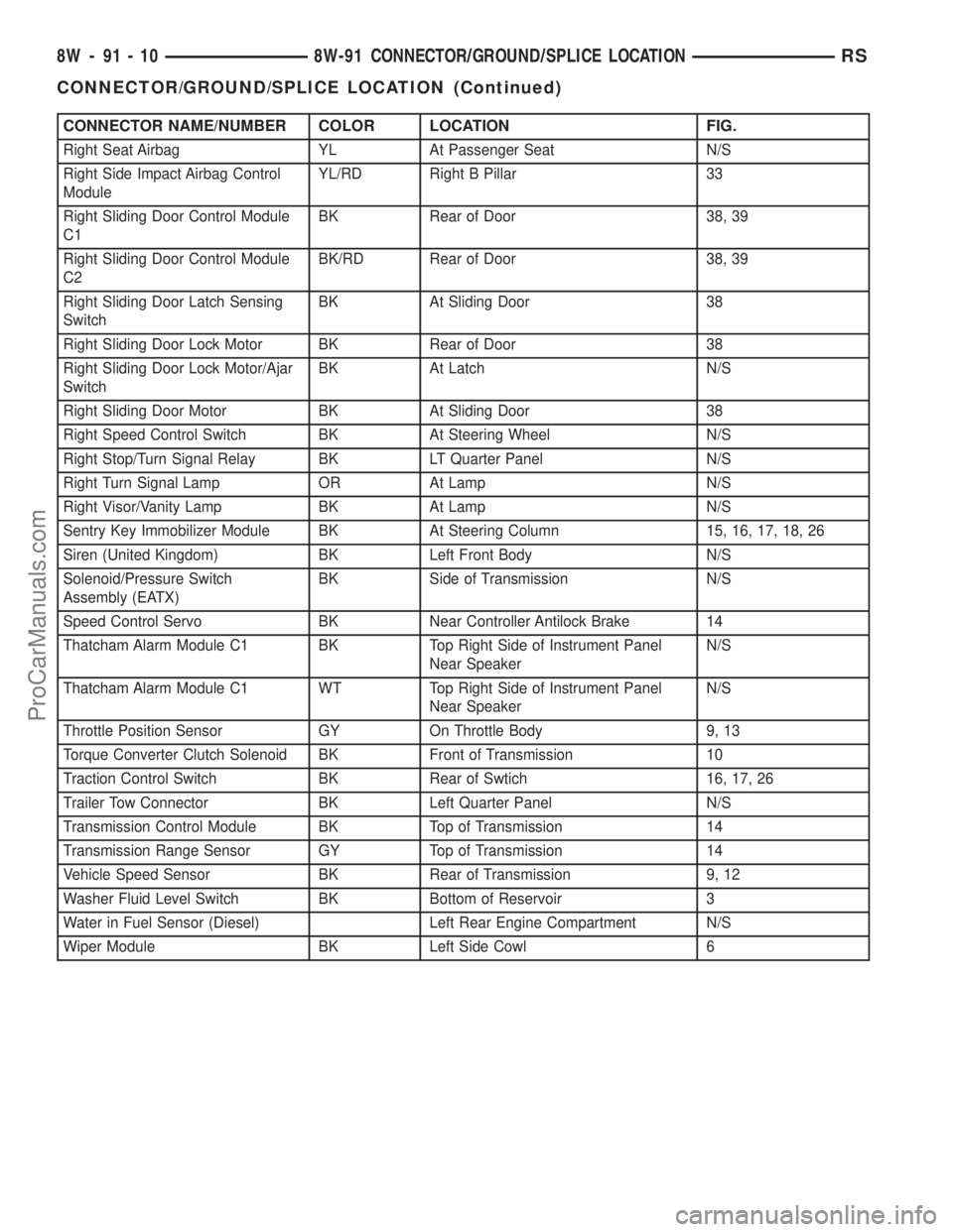
CONNECTOR NAME/NUMBER COLOR LOCATION FIG.
Right Seat Airbag YL At Passenger Seat N/S
Right Side Impact Airbag Control
ModuleYL/RD Right B Pillar 33
Right Sliding Door Control Module
C1BK Rear of Door 38, 39
Right Sliding Door Control Module
C2BK/RD Rear of Door 38, 39
Right Sliding Door Latch Sensing
SwitchBK At Sliding Door 38
Right Sliding Door Lock Motor BK Rear of Door 38
Right Sliding Door Lock Motor/Ajar
SwitchBK At Latch N/S
Right Sliding Door Motor BK At Sliding Door 38
Right Speed Control Switch BK At Steering Wheel N/S
Right Stop/Turn Signal Relay BK LT Quarter Panel N/S
Right Turn Signal Lamp OR At Lamp N/S
Right Visor/Vanity Lamp BK At Lamp N/S
Sentry Key Immobilizer Module BK At Steering Column 15, 16, 17, 18, 26
Siren (United Kingdom) BK Left Front Body N/S
Solenoid/Pressure Switch
Assembly (EATX)BK Side of Transmission N/S
Speed Control Servo BK Near Controller Antilock Brake 14
Thatcham Alarm Module C1 BK Top Right Side of Instrument Panel
Near SpeakerN/S
Thatcham Alarm Module C1 WT Top Right Side of Instrument Panel
Near SpeakerN/S
Throttle Position Sensor GY On Throttle Body 9, 13
Torque Converter Clutch Solenoid BK Front of Transmission 10
Traction Control Switch BK Rear of Swtich 16, 17, 26
Trailer Tow Connector BK Left Quarter Panel N/S
Transmission Control Module BK Top of Transmission 14
Transmission Range Sensor GY Top of Transmission 14
Vehicle Speed Sensor BK Rear of Transmission 9, 12
Washer Fluid Level Switch BK Bottom of Reservoir 3
Water in Fuel Sensor (Diesel) Left Rear Engine Compartment N/S
Wiper Module BK Left Side Cowl 6
8W - 91 - 10 8W-91 CONNECTOR/GROUND/SPLICE LOCATIONRS
CONNECTOR/GROUND/SPLICE LOCATION (Continued)
ProCarManuals.com
Page 1161 of 2399
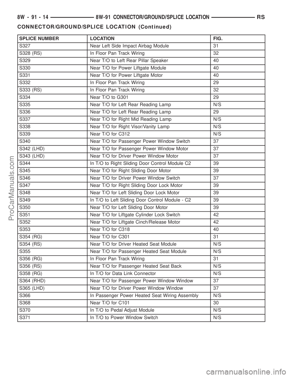
SPLICE NUMBER LOCATION FIG.
S327 Near Left Side Impact Airbag Module 31
S328 (RS) In Floor Pan Track Wiring 32
S329 Near T/O to Left Rear Pillar Speaker 40
S330 Near T/O for Power Liftgate Module 40
S331 Near T/O for Power Liftgate Motor 40
S332 In Floor Pan Track Wiring 29
S333 (RS) In Floor Pan Track Wiring 32
S334 Near T/O to G301 29
S335 Near T/O for Left Rear Reading Lamp N/S
S336 Near T/O for Left Rear Reading Lamp 29
S337 Near T/O for Right Mid Reading Lamp N/S
S338 Near T/O for Right Visor/Vanity Lamp N/S
S339 Near T/O for C312 N/S
S340 Near T/O for Passenger Power Window Switch 37
S342 (LHD) Near T/O for Passenger Power Window Motor 37
S343 (LHD) Near T/O for Driver Power Window Motor 37
S344 In T/O to Right Sliding Door Control Module C2 39
S345 Near T/O for Right Sliding Door Motor 39
S346 Near T/O for Driver Power Window Switch 37
S347 Near T/O for Right Sliding Door Lock Motor 39
S348 Near T/O for Left Sliding Door Lock Motor 39
S349 In T/O to Left Sliding Door Control Module - C2 39
S350 Near T/O for Left Sliding Door Motor 39
S351 Near T/O for Liftgate Cylinder Lock Switch 42
S352 Near T/O for Liftgate Cinch/Release Motor 42
S353 Near T/O for C318 40
S354 (RG) Near T/O for C301 31
S354 (RS) Near T/O for Driver Heated Seat Module N/S
S355 Near T/O for Passenger Heated Seat Module N/S
S356 (RG) In Floor Pan Track Wiring 31
S356 (RS) Near T/O for Passenger Heated Seat Back N/S
S358 (RG) In T/O for Data Link Connector N/S
S364 (RHD) Near T/O for Passenger Power Window Window 37
S365 (LHD) Near T/O for Driver Power Window Window 37
S366 In Passenger Power Heated Seat Wiring Assembly N/S
S368 Near T/O for C101 30
S370 In T/O to Pedal Adjust Module N/S
S371 In T/O to Power Window Switch N/S
8W - 91 - 14 8W-91 CONNECTOR/GROUND/SPLICE LOCATIONRS
CONNECTOR/GROUND/SPLICE LOCATION (Continued)
ProCarManuals.com
Page 1201 of 2399
WARNING: ON VEHICLES EQUIPPED WITH AIR-
BAGS, REFER TO RESTRAINTS BEFORE ATTEMPT-
ING ANY STEERING WHEEL, STEERING COLUMN,
SEAT OR INSTRUMENT PANEL COMPONENT DIAG-
NOSIS OR SERVICE. FAILURE TO TAKE THE
PROPER PRECAUTIONS COULD RESULT IN ACCI-
DENTAL AIRBAG DEPLOYMENT AND POSSIBLE
PERSONAL INJURY.
(1) Check the fused B(+) fuse in the Integrated
Power Module (IPM). If OK, go to Step 2. If not OK,
repair the shorted circuit or component as required
and replace the faulty fuse.
(2) Check for battery voltage at the fused B(+) fuse
in the IPM. If OK, go to Step 3. If not OK, repair the
open fused B(+) circuit to the IPM fuse as required.
(3)
Open the power outlet door. Check for continuity
between the inside circumference of the power outlet
receptacle and a good ground. There should be continu-
ity. If OK, go to Step 4. If not OK, go to Step 5.
(4) Check for battery voltage at the insulated con-
tact located at the back of the power outlet recepta-
cle. If not OK, go to Step 5.
(5) Disconnect and isolate the battery negative
cable. Remove the appropriate bezel. Check for conti-
nuity between the ground circuit cavity of the power
outlet wire harness connector and a good ground.
There should be continuity. If OK, go to Step 6. If not
OK, repair the open ground circuit to ground as
required.
(6) Connect the battery negative cable. Check for
battery voltage at the fused B(+) circuit cavity of the
power outlet wire harness connector. If OK, replace
the faulty power outlet receptacle. If not OK, repair
the open fused B(+) circuit to the IPM fuse as
required.
REMOVAL
(1) Disconnect and isolate the battery negative
cable.
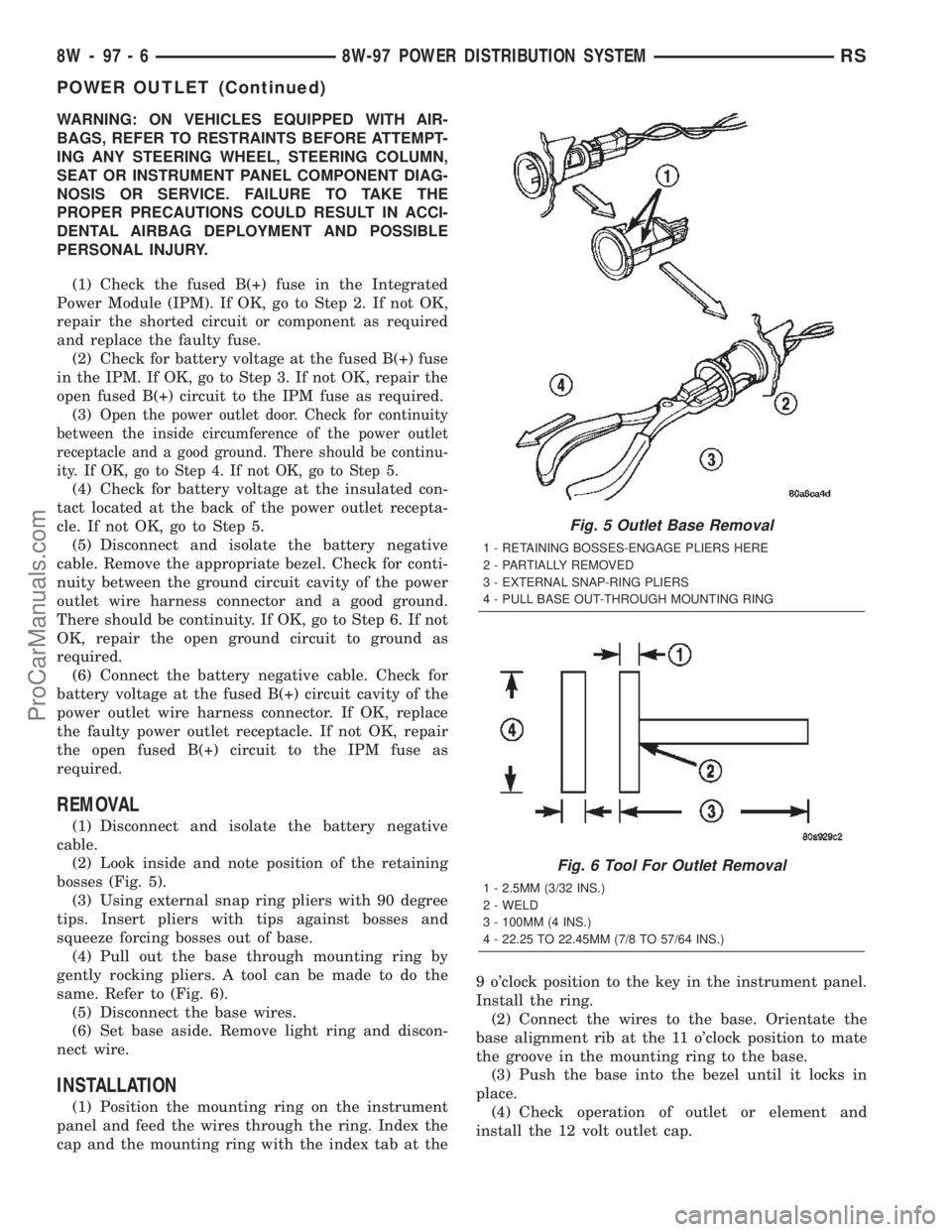
(2) Look inside and note position of the retaining
bosses (Fig. 5).
(3) Using external snap ring pliers with 90 degree
tips. Insert pliers with tips against bosses and
squeeze forcing bosses out of base.
(4) Pull out the base through mounting ring by
gently rocking pliers. A tool can be made to do the
same. Refer to (Fig. 6).
(5) Disconnect the base wires.
(6) Set base aside. Remove light ring and discon-
nect wire.
INSTALLATION
(1) Position the mounting ring on the instrument
panel and feed the wires through the ring. Index the
cap and the mounting ring with the index tab at the9 o'clock position to the key in the instrument panel.
Install the ring.
(2) Connect the wires to the base. Orientate the
base alignment rib at the 11 o'clock position to mate
the groove in the mounting ring to the base.
(3) Push the base into the bezel until it locks in
place.
(4) Check operation of outlet or element and
install the 12 volt outlet cap.
Fig. 5 Outlet Base Removal
1 - RETAINING BOSSES-ENGAGE PLIERS HERE
2 - PARTIALLY REMOVED
3 - EXTERNAL SNAP-RING PLIERS
4 - PULL BASE OUT-THROUGH MOUNTING RING
Fig. 6 Tool For Outlet Removal
1 - 2.5MM (3/32 INS.)
2 - WELD
3 - 100MM (4 INS.)
4 - 22.25 TO 22.45MM (7/8 TO 57/64 INS.)
8W - 97 - 6 8W-97 POWER DISTRIBUTION SYSTEMRS
POWER OUTLET (Continued)
ProCarManuals.com
Page 1513 of 2399
COLUMN
TABLE OF CONTENTS
page page
COLUMN
DESCRIPTION - STEERING COLUMN.......10
WARNING
WARNINGS AND CAUTIONS.............10
DIAGNOSIS AND TESTING - STEERING
COLUMN............................12
REMOVAL.............................12
INSTALLATION.........................13
SPECIFICATIONS
COLUMN TORQUE....................14
IGNITION SWITCH
REMOVAL.............................15
INSTALLATION.........................16
LOCK CYLINDER HOUSING
DESCRIPTION - IGNITION INTERLOCK......17
REMOVAL.............................17INSTALLATION.........................20
KEY/LOCK CYLINDER
DESCRIPTION.........................21
OPERATION...........................21
REMOVAL.............................22
INSTALLATION.........................22
GEAR SHIFT LEVER
REMOVAL.............................22
INSTALLATION.........................22
SHROUD
REMOVAL.............................23
INSTALLATION.........................23
STEERING WHEEL
REMOVAL.............................23
INSTALLATION.........................25
COLUMN
DESCRIPTION - STEERING COLUMN
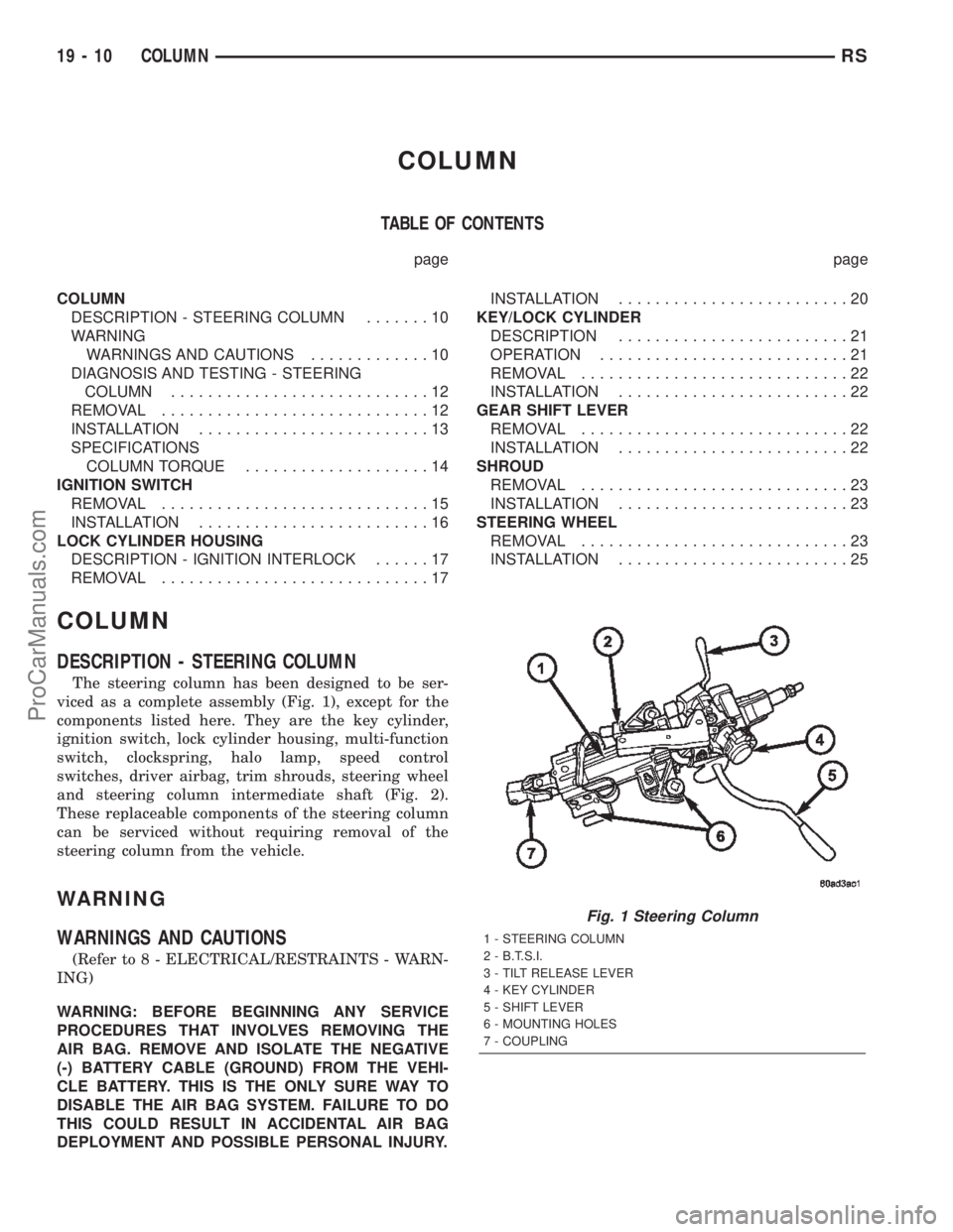
The steering column has been designed to be ser-
viced as a complete assembly (Fig. 1), except for the
components listed here. They are the key cylinder,
ignition switch, lock cylinder housing, multi-function
switch, clockspring, halo lamp, speed control
switches, driver airbag, trim shrouds, steering wheel
and steering column intermediate shaft (Fig. 2).
These replaceable components of the steering column
can be serviced without requiring removal of the
steering column from the vehicle.
WARNING
WARNINGS AND CAUTIONS
(Refer to 8 - ELECTRICAL/RESTRAINTS - WARN-
ING)
WARNING: BEFORE BEGINNING ANY SERVICE
PROCEDURES THAT INVOLVES REMOVING THE
AIR BAG. REMOVE AND ISOLATE THE NEGATIVE
(-) BATTERY CABLE (GROUND) FROM THE VEHI-
CLE BATTERY. THIS IS THE ONLY SURE WAY TO
DISABLE THE AIR BAG SYSTEM. FAILURE TO DO
THIS COULD RESULT IN ACCIDENTAL AIR BAG
DEPLOYMENT AND POSSIBLE PERSONAL INJURY.
Fig. 1 Steering Column
1 - STEERING COLUMN
2 - B.T.S.I.
3 - TILT RELEASE LEVER
4 - KEY CYLINDER
5 - SHIFT LEVER
6 - MOUNTING HOLES
7 - COUPLING
19 - 10 COLUMNRS
ProCarManuals.com
Page 1515 of 2399
WARNING: THE AIR BAG SYSTEM IS A SENSITIVE,
COMPLEX ELECTRO-MECHANICAL UNIT. BEFORE
ATTEMPTING TO DIAGNOSE, REMOVE OR INSTALL
THE AIR BAG SYSTEM COMPONENTS YOU MUST
FIRST DISCONNECT AND ISOLATE THE BATTERY
NEGATIVE (GROUND) CABLE. THEN WAIT TWO
MINUTES FOR THE SYSTEM CAPACITOR TO DIS-
CHARGE. FAILURE TO DO SO COULD RESULT IN
ACCIDENTAL DEPLOYMENT OF THE AIR BAG AND
POSSIBLE PERSONAL INJURY. THE FASTENERS,
SCREWS, AND BOLTS, ORIGINALLY USED FOR
THE AIR BAG COMPONENTS, HAVE SPECIAL
COATINGS AND ARE SPECIFICALLY DESIGNED
FOR THE AIR BAG SYSTEM. THEY MUST NEVER
BE REPLACED WITH ANY SUBSTITUTES. ANYTIME
A NEW FASTENER IS NEEDED, REPLACE WITH
THE CORRECT FASTENERS PROVIDED IN THE
SERVICE PACKAGE OR FASTENERS LISTED IN
THE PARTS BOOKS.
WARNING: SAFETY GOGGLES SHOULD BE WORN
AT ALL TIMES WHEN WORKING ON STEERING
COLUMNS.
CAUTION: Disconnect negative (ground) cable from
the battery before servicing any column compo-
nent.
CAUTION: Do not attempt to remove the pivot pins
to disassemble the tilting mechanism. Damage will
occur.
DIAGNOSIS AND TESTING - STEERING
COLUMN
For diagnosis of conditions relating to the steering
column (Refer to 19 - STEERING - DIAGNOSIS ANDTESTING) and (Refer to 19 - STEERING - DIAGNO-
SIS AND TESTING).
REMOVAL
NOTE: Before proceeding, (Refer to 19 - STEERING/
COLUMN - WARNING).
(1) Make sure the front wheels of the vehicle are
in the STRAIGHT AHEAD position before beginning
the column removal procedure.
(2) Disconnect negative (ground) cable from the
battery and isolate cable from battery terminal.
(3) Remove the lower shroud (Refer to 19 -
STEERING/COLUMN/LOWER SHROUD - REMOV-
AL).
(4) Remove the traction off switch.
(5) Remove the upper shroud.
(6) Remove the cluster trim bezel (Refer to 23 -
BODY/INSTRUMENT PANEL/CLUSTER BEZEL -
REMOVAL).
(7) Remove the knee blocker (Refer to 23 - BODY/
INSTRUMENT PANEL/STEERING COLUMN
OPENING COVER - REMOVAL).
(8) Remove the parking brake handle link.
(9) Remove the knee blocker reinforcement (Refer
to 23 - BODY/INSTRUMENT PANEL/KNEE
BLOCKER - REMOVAL).
(10) Remove the airbag (Refer to 8 - ELECTRI-
CAL/RESTRAINTS/DRIVER AIRBAG - REMOVAL).
(11) Remove the steering wheel retaining nut.
(12) Remove the vibration damper weight.
(13) Remove the steering wheel (Refer to 19 -
STEERING/COLUMN/STEERING WHEEL -
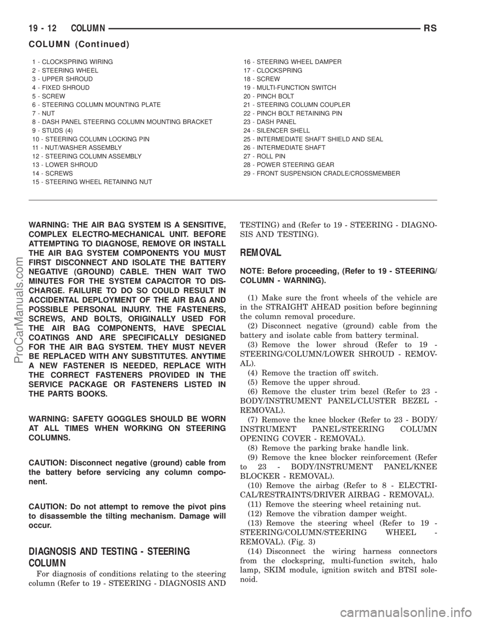
REMOVAL). (Fig. 3)
(14) Disconnect the wiring harness connectors
from the clockspring, multi-function switch, halo
lamp, SKIM module, ignition switch and BTSI sole-
noid.
1 - CLOCKSPRING WIRING
2 - STEERING WHEEL
3 - UPPER SHROUD
4 - FIXED SHROUD
5 - SCREW
6 - STEERING COLUMN MOUNTING PLATE
7 - NUT
8 - DASH PANEL STEERING COLUMN MOUNTING BRACKET
9 - STUDS (4)
10 - STEERING COLUMN LOCKING PIN
11 - NUT/WASHER ASSEMBLY
12 - STEERING COLUMN ASSEMBLY
13 - LOWER SHROUD
14 - SCREWS
15 - STEERING WHEEL RETAINING NUT16 - STEERING WHEEL DAMPER
17 - CLOCKSPRING
18 - SCREW
19 - MULTI-FUNCTION SWITCH
20 - PINCH BOLT
21 - STEERING COLUMN COUPLER
22 - PINCH BOLT RETAINING PIN
23 - DASH PANEL
24 - SILENCER SHELL
25 - INTERMEDIATE SHAFT SHIELD AND SEAL
26 - INTERMEDIATE SHAFT
27 - ROLL PIN
28 - POWER STEERING GEAR
29 - FRONT SUSPENSION CRADLE/CROSSMEMBER
19 - 12 COLUMNRS
COLUMN (Continued)
ProCarManuals.com
Page 1516 of 2399

(15) Disconnect the shift cable at the lever. (Fig. 4)
(16) Remove the pinch side clip, then remove the
cable from the bracket on the column.
(17) Remove the pinch bolt coupling. (Fig. 5)
(18) Loosen the two lower mounting nuts.
(19) Remove the two upper mounting nuts
(20) Remove the steering column.
(21) Remove the clockspring (Refer to 8 - ELEC-
TRICAL/RESTRAINTS/CLOCKSPRING - REMOV-
AL). (Fig. 6)
(22) Remove the mounting plate with the multi-
function switch.
(23) Remove the halo-lamp.(24) Remove the ignition key cylinder (Refer to 19
- STEERING/COLUMN/KEY/LOCK CYLINDER -
REMOVAL).
(25) Remove the BTSI.
INSTALLATION
To service the steering wheel components or the
airbag (Refer to 8 - ELECTRICAL/RESTRAINTS/
DRIVER AIRBAG - REMOVAL). Follow all WARN-
INGS AND CAUTIONS.
(1) Make sure the front wheels of the vehicle are
still in the STRAIGHT AHEAD position before begin-
ning the column installation procedure.
(2) Install the BTSI.
(3) Install the ignition key cylinder (Refer to 19 -
STEERING/COLUMN/KEY/LOCK CYLINDER -
INSTALLATION).
(4) Install the halo-lamp.
Fig. 3 STEERING WHEEL REMOVAL
1 - STEERING WHEEL
2 - PULLER
Fig. 4 SHIFT CABLE MOUNTING
1 - SHIFT CABLE MOUNT
2 - SHIFT LEVER
Fig. 5 PINCH BOLT
1 - PINCH BOLT
2 - STEERING COLUMN
Fig. 6 CLOCKSPRING
RSCOLUMN19-13
COLUMN (Continued)
ProCarManuals.com