2002 CHRYSLER CARAVAN charging
[x] Cancel search: chargingPage 513 of 2399

(4) Install the headlamp unit.
(5) Connect the battery negative cable.
HEADLAMP
DIAGNOSIS AND TESTING - HEADLAMP
When a vehicle experiences problems with the
headlamp system, verify the condition of the battery
connections, fuses, charging system, headlamp bulbs,
wire connectors, relay, high beam switch, dimmer
switch, and headlamp switch. Refer to the appropri-
ate wiring information.
Each vehicle is equipped with various lamp assem-
blies. A good ground is necessary for proper lighting
operation. Grounding is provided by the lamp socket
when it comes in contact with the metal body, or
through a separate ground wire.
When changing lamp bulbs check the socket for
corrosion. If corrosion is present, clean it with a wire
brush.
When it is necessary to remove components to ser-
vice another, it should not be necessary to apply
excessive force or bend a component to remove it.
Before damaging a trim component, verify hidden
fasteners or captured edges are not holding the com-
ponent in place.
HEADLAMP DIAGNOSIS
CONDITION POSSIBLE CAUSES CORRECTION
HEADLAMPS ARE DIM
WITH ENGINE IDLING
OR IGNITION TURNED
OFF.1. Loose or corroded battery
cables.1. Clean and secure battery cable clamps and
posts.
2. Loose or worn generator drive
belt.2. Adjust or replace generator drive belt.
3. Charging system output too low. 3. Test and repair charging system, refer to
Electrical, Charging
4. Battery has insufficient charge. 4. Test battery state-of-charge, refer to
Electrical, Battery System.
5. Battery is sulfated or shorted. 5. Load test battery, refer to Electrical, Battery
System.
6. Poor lighting circuit Z343/Z344-
ground.6. Test for voltage drop across Z343/Z344-
ground locations, refer to Electrical, Wiring
Diagram Information.
HEADLAMP BULBS
BURN OUT
FREQUENTLY.1. Integrated Power Module (IPM)
not controlling voltage.1. Test and repair Integrated Power Module.
2. Loose or corroded terminals or
splices in circuit.2. Inspect and repair all connectors and splices.
Refer to Electrical, Wiring Information.
Fig. 11 FRONT POSITION LAMP
1 - TURN SIGNAL LAMP
2 - HIGH BEAM LAMP
3 - FRONT POSITION LAMP
4 - LOW BEAM LAMP
8L - 12 LAMPS/LIGHTING - EXTERIORRS
FRONT POSITION LAMP - EXPORT (Continued)
ProCarManuals.com
Page 514 of 2399

CONDITION POSSIBLE CAUSES CORRECTION
HEADLAMPS ARE DIM
WITH ENGINE
RUNNING ABOVE IDLE.1. Charging system output too low. 1. Test and repair charging system, refer to
Electrical, Wiring Information.
2. Poor lighting circuit Z343/Z344-
ground.2. Test for voltage drop across Z343/Z344-
ground locations, refer to Electrical, Wiring
Information.
3. High resistance in headlamp
circuit.3. Test amperage draw of headlamp circuit.
HEADLAMPS FLASH
RANDOMLY1. Poor lighting circuit Z343/Z344-
ground.1. Test for voltage drop across Z343/Z344-
ground locations, refer to Electrical, Wiring
Information.
2. Variable resistance in headlamp
circuit.2. Test amperage draw of headlamp circuit.
3. Loose or corroded terminals or
splices in circuit.3. Inspect and repair all connectors and splices,
refer to Electrical, Wiring Information.
4. Faulty headlamp switch. 4. Replace headlamp switch.
HEADLAMPS DO NOT
ILLUMINATE.1. No voltage to headlamps. 1. Repair open headlamp circuit, refer to
Electrical, Wiring Information.
2. No Z343/Z344-ground at
headlamps.2. Repair circuit ground, refer to Electrical,
Wiring Information.
3. Broken connector terminal or
wire splice in headlamp circuit.3. Repair connector terminal or wire splice.
4. Faulty or burned out bulb. 4. Replace headlamp bulb(s).
5. Body Control Module
malfunction.5. Refer to appropriate Body Control Module
diagnostics.
6. PCI Bus Communication 6. Verify messages being transmitted by BCM
and received by FCM.
7. IPM/FCM Malfunction. 7. Refer to appropriate IPM/FCM diagnostics.
HEADLAMPS ON WITH
IGNITION IN RUN, WITH
HEADLAMP SWITCH
OFF.1. Faulty headlamp switch. 1. Replace headlamp switch (review BCM
logged faults).
2. Diagnostic tool indicates (4.7 -
5.0V) on headlamp switch input to
BCM.2. Inspect and repair terminals, connectors and
open circuits.
3. PCI Bus Communication. 3. Verify messages being transmitted by BCM
and received by FCM.
RSLAMPS/LIGHTING - EXTERIOR8L-13
HEADLAMP (Continued)
ProCarManuals.com
Page 658 of 2399

WIRING
TABLE OF CONTENTS
page page
WIRING DIAGRAM INFORMATION....... 8W-01-1
COMPONENT INDEX.................. 8W-02-1
POWER DISTRIBUTION............... 8W-10-1
GROUND DISTRIBUTION.............. 8W-15-1
BUS COMMUNICATIONS.............. 8W-18-1
CHARGING SYSTEM.................. 8W-20-1
STARTING SYSTEM.................. 8W-21-1
FUEL/IGNITION SYSTEM.............. 8W-30-1
TRANSMISSION CONTROL SYSTEM..... 8W-31-1
VEHICLE SPEED CONTROL............ 8W-33-1
ANTILOCK BRAKES................... 8W-35-1
VEHICLE THEFT SECURITY SYSTEM..... 8W-39-1
INSTRUMENT CLUSTER............... 8W-40-1
HORN/CIGAR LIGHTER/POWER OUTLET . . 8W-41-1
AIR CONDITIONING-HEATER........... 8W-42-1
AIRBAG SYSTEM.................... 8W-43-1
INTERIOR LIGHTING.................. 8W-44-1
BODY CONTROL MODULE............. 8W-45-1MESSAGE CENTER................... 8W-46-1
AUDIO SYSTEM..................... 8W-47-1
REAR WINDOW DEFOGGER............ 8W-48-1
OVERHEAD CONSOLE................. 8W-49-1
FRONT LIGHTING.................... 8W-50-1
REAR LIGHTING..................... 8W-51-1
TURN SIGNALS...................... 8W-52-1
WIPERS............................ 8W-53-1
TRAILER TOW....................... 8W-54-1
POWER WINDOWS................... 8W-60-1
POWER DOOR LOCKS................ 8W-61-1
POWER MIRRORS................... 8W-62-1
POWER SEATS...................... 8W-63-1
SPLICE INFORMATION................ 8W-70-1
CONNECTOR PIN-OUTS............... 8W-80-1
CONNECTOR/GROUND/SPLICE
LOCATION........................ 8W-91-1
POWER DISTRIBUTION SYSTEM........ 8W-97-1 RSWIRING
8W-1
ProCarManuals.com
Page 665 of 2399

DESCRIPTION - CIRCUIT FUNCTIONS
All circuits in the diagrams use an alpha/numeric
code to identify the wire and it's function. To identify
which circuit code applies to a system, refer to the
Circuit Identification Code Chart. This chart shows
the main circuits only and does not show the second-
ary codes that may apply to some models.
CIRCUIT IDENTIFICATION CODE CHART
CIRCUIT FUNCTION
A BATTERY FEED
B BRAKE CONTROLS
C CLIMATE CONTROLS
D DIAGNOSTIC CIRCUITS
E DIMMING ILLUMINATION
CIRCUITS
F FUSED CIRCUITS
G MONITORING CIRCUITS
(GAUGES)
H OPEN
I NOT USED
J OPEN
K POWERTRAIN CONTROL
MODULE
L EXTERIOR LIGHTING
M INTERIOR LIGHTING
N NOT USED
O NOT USED
P POWER OPTION (BATTERY
FEED)
Q POWER OPTIONS (IGNITION
FEED)
R PASSIVE RESTRAINT
S SUSPENSION/STEERING
T TRANSMISSION/TRANSAXLE/
TRANSFER CASE
U OPEN
V SPEED CONTROL, WIPER/
WASHER
W OPEN
X AUDIO SYSTEMS
Y OPEN
Z GROUNDS
DESCRIPTION - SECTION IDENTIFICATION AND
INFORMATION
The wiring diagrams are grouped into individual
sections. If a component is most likely found in a par-
ticular group, it will be shown complete (all wires,
connectors, and pins) within that group. For exam-
ple, the Auto Shutdown Relay is most likely to be
found in Group 30, so it is shown there complete. It
can, however, be shown partially in another group if
it contains some associated wiring.
Splice diagrams in Section 8W-70 show the entire
splice and provide references to other sections the
splices serves. Section 8W-70 only contains splice dia-
grams that are not shown in their entirety some-
where else in the wiring diagrams.
Section 8W-80 shows each connector and the cir-
cuits involved with that connector. The connectors
are identified using the name/number on the dia-
gram pages.
WIRING SECTION CHART
GROUP TOPIC
8W-01 thru
8W-09General information and Diagram
Overview
8W-10 thru
8W-19Main Sources of Power and
Vehicle Grounding
8W-20 thru
8W-29Starting and Charging
8W-30 thru
8W-39Powertrain/Drivetrain Systems
8W-40 thru
8W-49Body Electrical items and A/C
8W-50 thru
8W-59Exterior Lighting, Wipers and
Trailer Tow
8W-60 thru
8W-69Power Accessories
8W-70 Splice Information
8W-80 Connector Pin Outs
8W-91 Connector, Ground and Splice
Locations
8W - 01 - 6 8W-01 WIRING DIAGRAM INFORMATIONRS
WIRING DIAGRAM INFORMATION (Continued)
ProCarManuals.com
Page 778 of 2399

8W-20 CHARGING SYSTEM
Component Page
Auto Shut Down Relay................ 8W-20-2
Battery.......................... 8W-20-2, 3
Battery Temperature Sensor............ 8W-20-3
ECM/PCM Relay..................... 8W-20-3
Engine Control Module................ 8W-20-3
Fuse 16.......................... 8W-20-2, 3
Fuse 17............................ 8W-20-2Component Page
Fuselink......................... 8W-20-2, 3
G100............................ 8W-20-2, 3
G101............................ 8W-20-2, 3
Generator........................ 8W-20-2, 3
Integrated Power Module............ 8W-20-2, 3
Powertrain Control Module............. 8W-20-2
Starter Motor..................... 8W-20-2, 3
RS8W-20 CHARGING SYSTEM8W-20-1
ProCarManuals.com
Page 1289 of 2399

(33)AWD equipped:Remove the power transfer
unit (PTU) (Refer to 21 - TRANSMISSION/TRANS-
AXLE/POWER TRANSFER UNIT - REMOVAL).
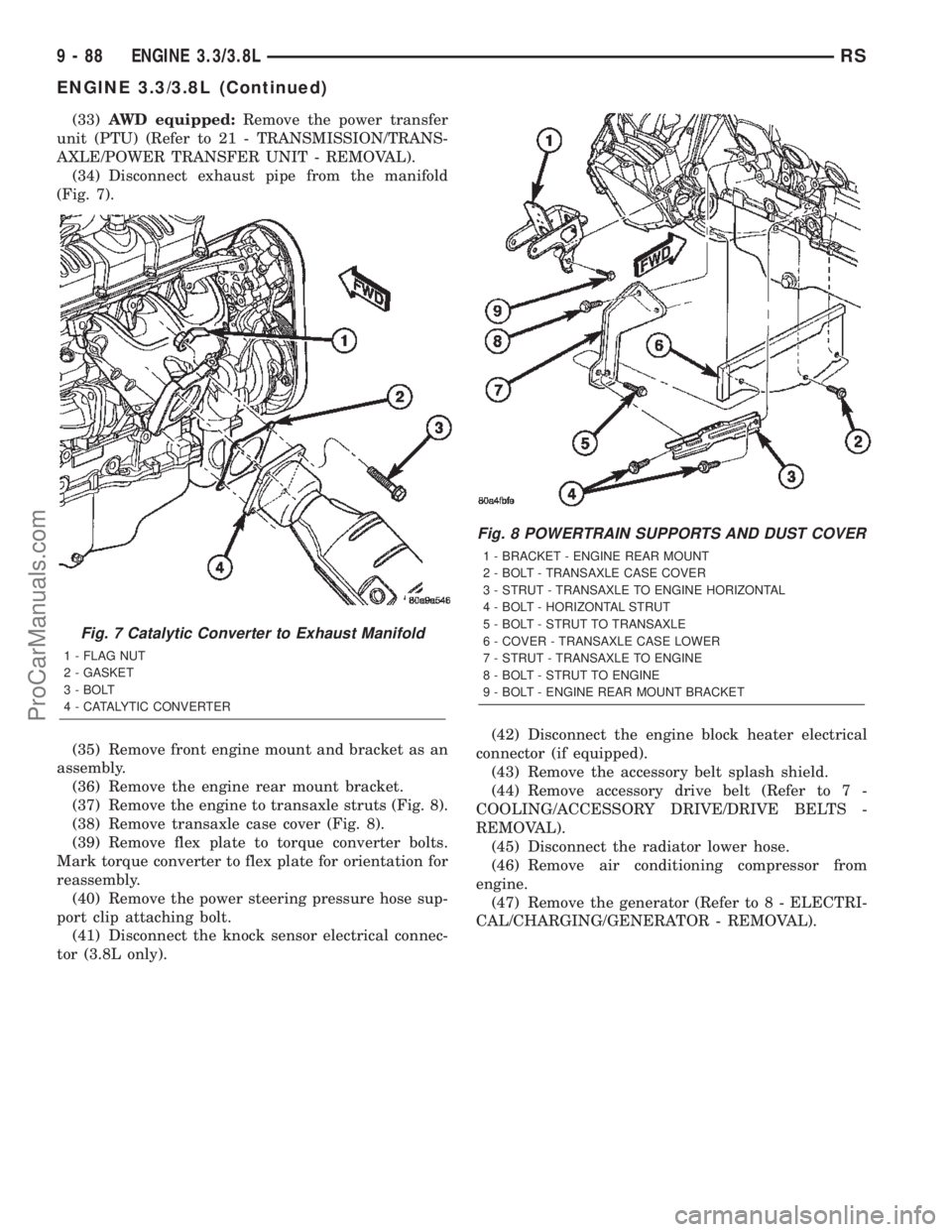
(34) Disconnect exhaust pipe from the manifold
(Fig. 7).
(35) Remove front engine mount and bracket as an
assembly.
(36) Remove the engine rear mount bracket.
(37) Remove the engine to transaxle struts (Fig. 8).
(38) Remove transaxle case cover (Fig. 8).
(39) Remove flex plate to torque converter bolts.
Mark torque converter to flex plate for orientation for
reassembly.
(40) Remove the power steering pressure hose sup-
port clip attaching bolt.
(41) Disconnect the knock sensor electrical connec-
tor (3.8L only).(42) Disconnect the engine block heater electrical
connector (if equipped).
(43) Remove the accessory belt splash shield.
(44) Remove accessory drive belt (Refer to 7 -
COOLING/ACCESSORY DRIVE/DRIVE BELTS -
REMOVAL).
(45) Disconnect the radiator lower hose.
(46) Remove air conditioning compressor from
engine.
(47) Remove the generator (Refer to 8 - ELECTRI-
CAL/CHARGING/GENERATOR - REMOVAL).
Fig. 7 Catalytic Converter to Exhaust Manifold
1 - FLAG NUT
2 - GASKET
3 - BOLT
4 - CATALYTIC CONVERTER
Fig. 8 POWERTRAIN SUPPORTS AND DUST COVER
1 - BRACKET - ENGINE REAR MOUNT
2 - BOLT - TRANSAXLE CASE COVER
3 - STRUT - TRANSAXLE TO ENGINE HORIZONTAL
4 - BOLT - HORIZONTAL STRUT
5 - BOLT - STRUT TO TRANSAXLE
6 - COVER - TRANSAXLE CASE LOWER
7 - STRUT - TRANSAXLE TO ENGINE
8 - BOLT - STRUT TO ENGINE
9 - BOLT - ENGINE REAR MOUNT BRACKET
9 - 88 ENGINE 3.3/3.8LRS
ENGINE 3.3/3.8L (Continued)
ProCarManuals.com
Page 1291 of 2399

INSTALLATION - ENGINE ASSEMBLY
(1) Position engine and transmission assembly
under vehicle. Slowly lower the vehicle down over the
engine and transmission. It is necessary to move the
engine/transmission assembly with the dolly for
clearance around body flanges.
(2) Align engine and transmission mounts to
attaching points. Install mounting bolts at the right
engine mount (Fig. 13) and left transmission mount
(Fig. 14).
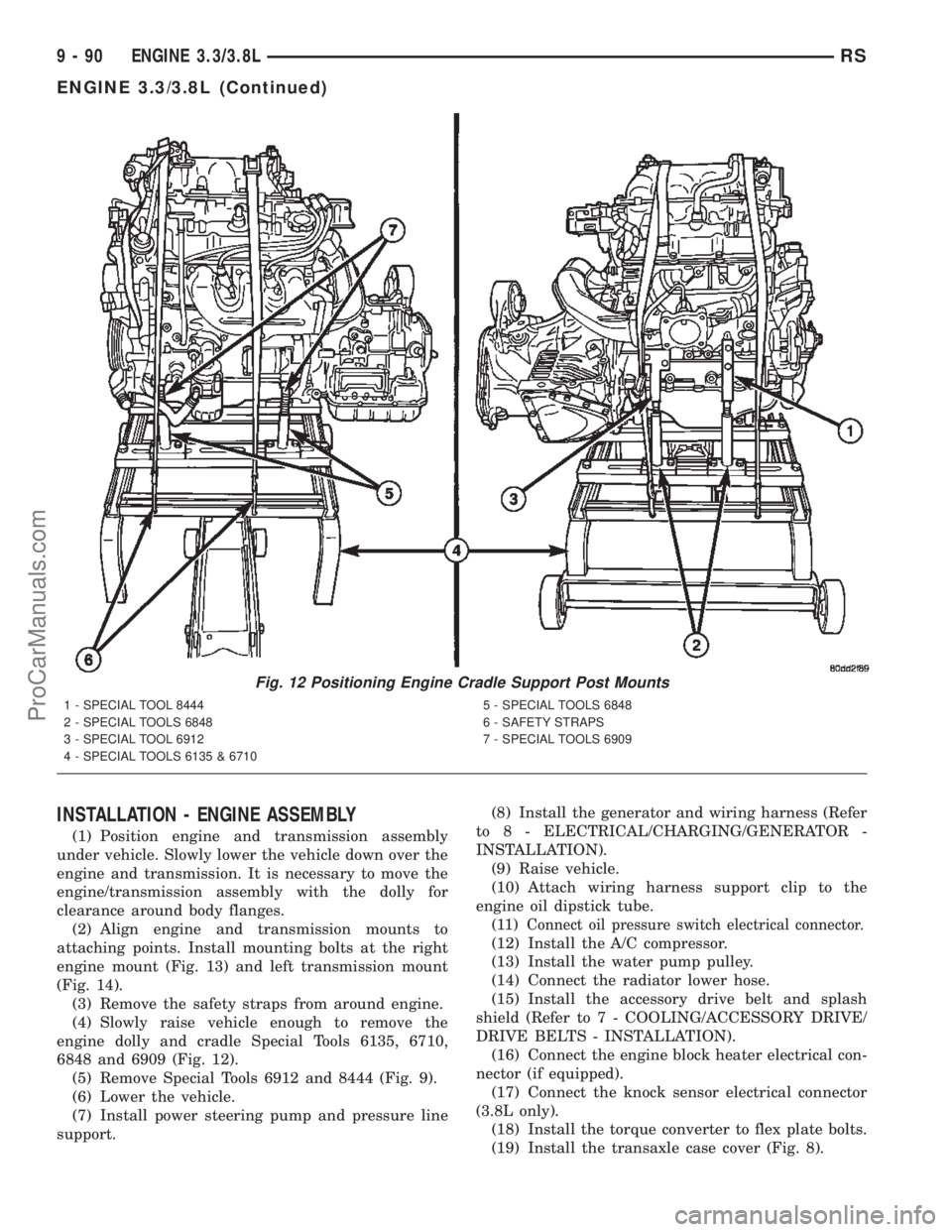
(3) Remove the safety straps from around engine.
(4) Slowly raise vehicle enough to remove the
engine dolly and cradle Special Tools 6135, 6710,
6848 and 6909 (Fig. 12).
(5) Remove Special Tools 6912 and 8444 (Fig. 9).
(6) Lower the vehicle.
(7) Install power steering pump and pressure line
support.(8) Install the generator and wiring harness (Refer
to 8 - ELECTRICAL/CHARGING/GENERATOR -
INSTALLATION).
(9) Raise vehicle.
(10) Attach wiring harness support clip to the
engine oil dipstick tube.
(11)
Connect oil pressure switch electrical connector.
(12) Install the A/C compressor.
(13) Install the water pump pulley.
(14) Connect the radiator lower hose.
(15) Install the accessory drive belt and splash
shield (Refer to 7 - COOLING/ACCESSORY DRIVE/
DRIVE BELTS - INSTALLATION).
(16) Connect the engine block heater electrical con-
nector (if equipped).
(17) Connect the knock sensor electrical connector
(3.8L only).
(18) Install the torque converter to flex plate bolts.
(19) Install the transaxle case cover (Fig. 8).
Fig. 12 Positioning Engine Cradle Support Post Mounts
1 - SPECIAL TOOL 8444
2 - SPECIAL TOOLS 6848
3 - SPECIAL TOOL 6912
4 - SPECIAL TOOLS 6135 & 67105 - SPECIAL TOOLS 6848
6 - SAFETY STRAPS
7 - SPECIAL TOOLS 6909
9 - 90 ENGINE 3.3/3.8LRS
ENGINE 3.3/3.8L (Continued)
ProCarManuals.com
Page 1380 of 2399

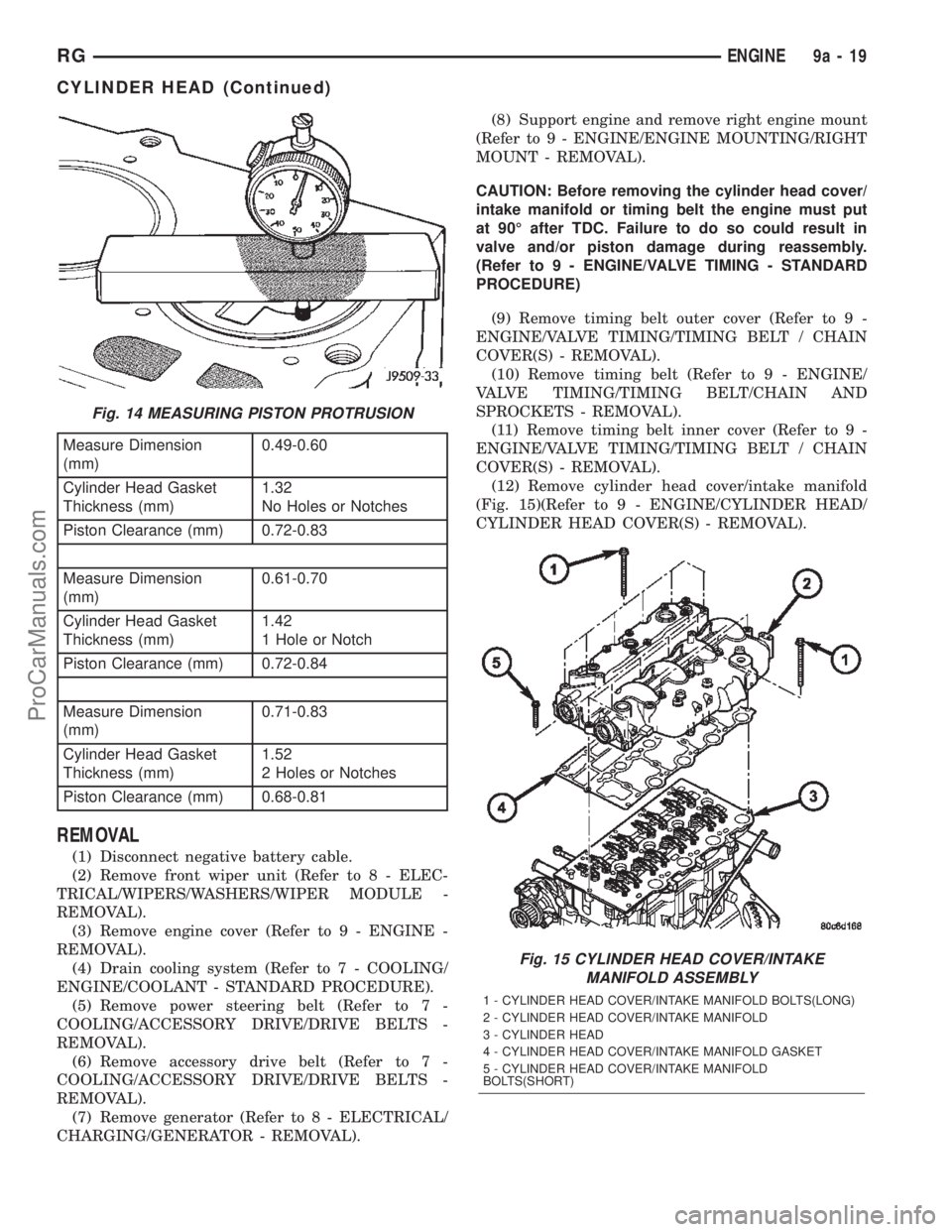
Measure Dimension
(mm)0.49-0.60
Cylinder Head Gasket
Thickness (mm)1.32
No Holes or Notches
Piston Clearance (mm) 0.72-0.83
Measure Dimension
(mm)0.61-0.70
Cylinder Head Gasket
Thickness (mm)1.42
1 Hole or Notch
Piston Clearance (mm) 0.72-0.84
Measure Dimension
(mm)0.71-0.83
Cylinder Head Gasket
Thickness (mm)1.52
2 Holes or Notches
Piston Clearance (mm) 0.68-0.81
REMOVAL
(1) Disconnect negative battery cable.
(2) Remove front wiper unit (Refer to 8 - ELEC-
TRICAL/WIPERS/WASHERS/WIPER MODULE -
REMOVAL).
(3) Remove engine cover (Refer to 9 - ENGINE -
REMOVAL).
(4) Drain cooling system (Refer to 7 - COOLING/
ENGINE/COOLANT - STANDARD PROCEDURE).
(5) Remove power steering belt (Refer to 7 -
COOLING/ACCESSORY DRIVE/DRIVE BELTS -
REMOVAL).
(6) Remove accessory drive belt (Refer to 7 -
COOLING/ACCESSORY DRIVE/DRIVE BELTS -
REMOVAL).
(7) Remove generator (Refer to 8 - ELECTRICAL/
CHARGING/GENERATOR - REMOVAL).(8) Support engine and remove right engine mount
(Refer to 9 - ENGINE/ENGINE MOUNTING/RIGHT
MOUNT - REMOVAL).
CAUTION: Before removing the cylinder head cover/
intake manifold or timing belt the engine must put
at 90É after TDC. Failure to do so could result in
valve and/or piston damage during reassembly.
(Refer to 9 - ENGINE/VALVE TIMING - STANDARD
PROCEDURE)
(9) Remove timing belt outer cover (Refer to 9 -
ENGINE/VALVE TIMING/TIMING BELT / CHAIN
COVER(S) - REMOVAL).
(10) Remove timing belt (Refer to 9 - ENGINE/
VALVE TIMING/TIMING BELT/CHAIN AND
SPROCKETS - REMOVAL).
(11) Remove timing belt inner cover (Refer to 9 -
ENGINE/VALVE TIMING/TIMING BELT / CHAIN
COVER(S) - REMOVAL).
(12) Remove cylinder head cover/intake manifold
(Fig. 15)(Refer to 9 - ENGINE/CYLINDER HEAD/
CYLINDER HEAD COVER(S) - REMOVAL).
Fig. 14 MEASURING PISTON PROTRUSION
Fig. 15 CYLINDER HEAD COVER/INTAKE
MANIFOLD ASSEMBLY
1 - CYLINDER HEAD COVER/INTAKE MANIFOLD BOLTS(LONG)
2 - CYLINDER HEAD COVER/INTAKE MANIFOLD
3 - CYLINDER HEAD
4 - CYLINDER HEAD COVER/INTAKE MANIFOLD GASKET
5 - CYLINDER HEAD COVER/INTAKE MANIFOLD
BOLTS(SHORT)
RGENGINE9a-19
CYLINDER HEAD (Continued)
ProCarManuals.com