2002 CHRYSLER CARAVAN lock
[x] Cancel search: lockPage 2303 of 2399
PLUMBING - FRONT
WARNING
WARNING
WARNING: DO NOT OPERATE DCHA IN AN
ENCLOSED AREA SUCH AS A GARAGE THAT
DOES NOT HAVE EXHAUST VENTILATION FACILI-
TIES. ALWAYS VENT THE DCHA'S EXHAUST WHEN
OPERATING THE DCHA. FAILURE TO FOLLOW
THESE INSTRUCTION MAY RESULT IN PERSONAL
INJURY OR DEATH.
ALLOW THE DCHA ASSEMBLY TO COOL BEFORE
PERFORMING A COMPONENT INSPECTION/RE-
PAIR/REPLACEMENT. FAILURE TO FOLLOW THESE
INSTRUCTIONS MY RESULT IN PERSONAL INJURY.
VERIFY THAT ALL DCHA FUEL LINES ARE
SECURELY FASTENED TO THEIR RESPECTIVE
COMPONENTS BEFORE THIS PROCEDURE.
WARNING
WARNING:: THE ENGINE COOLING SYSTEM IS
DESIGNED TO DEVELOP INTERNAL PRESSURES
OF 97 TO 123 KILOPASCALS (14 TO 18 POUNDS
PER SQUARE INCH). DO NOT REMOVE OR
LOOSEN THE COOLANT PRESSURE CAP, CYLIN-
DER BLOCK DRAIN PLUGS, RADIATOR DRAIN,
RADIATOR HOSES, HEATER HOSES, OR HOSE
CLAMPS WHILE THE SYSTEM IS HOT AND UNDER
PRESSURE. FAILURE TO OBSERVE THIS WARNING
CAN RESULT IN SERIOUS BURNS FROM THE
HEATED ENGINE COOLANT. ALLOW THE VEHICLE
TO COOL FOR A MINIMUM OF 15 MINUTES
BEFORE OPENING THE COOLING SYSTEM FOR
SERVICE.
WARNING: THE ENGINE COOLING SYSTEM CON-
TAINS ANTIFREEZE. ANTIFREEZE IS AN ETHYLENE
GLYCOL BASED COOLANT AND IS HARMFUL IF
SWALLOWED OR IF THE VAPORS ARE INHALED. IF
SWALLOWED, DRINK TWO GLASSES OF WATER
AND INDUCE VOMITING. IF VAPORS ARE INHALED,
MOVE TO AN AREA FOR FRESH AIR. SEEK MEDI-
CAL ATTENTION IMMEDIATELY. DO NOT STORE IN
OPEN OR UNMARKED CONTAINERS. WASH SKIN
AND CLOTHING THOROUGHLY AFTER COMING IN
CONTACT WITH ETHYLENE GLYCOL. KEEP OUT
OF REACH OF CHILDREN.
WARNING: DISPOSE OF ETHYLENE GLYCOL
BASED COOLANT PROPERLY. CONTACT YOURDEALER OR A LOCAL GOVERNMENT AGENCY FOR
THE LOCATION OF AN APPROVED ETHYLENE GLY-
COL COLLECTION AND/OR RECYCLING CENTER IN
YOUR AREA.
WARNING - A/C PLUMBING
WARNING:: THE AIR CONDITIONING SYSTEM CON-
TAINS REFRIGERANT UNDER HIGH PRESSURE.
SEVERE PERSONAL INJURY MAY RESULT FROM
IMPROPER SERVICE PROCEDURES. REPAIRS
SHOULD ONLY BE PERFORMED BY QUALIFIED
SERVICE PERSONNEL.
WARNING: AVOID BREATHING THE REFRIGERANT
AND REFRIGERANT OIL VAPOR OR MIST. EXPO-
SURE MAY IRRITATE THE EYES, NOSE, AND/OR
THROAT. WEAR EYE PROTECTION WHEN SERVIC-
ING THE AIR CONDITIONING REFRIGERANT SYS-
TEM. SERIOUS EYE INJURY CAN RESULT FROM
DIRECT CONTACT WITH THE REFRIGERANT. IF
EYE CONTACT OCCURS, SEEK MEDICAL ATTEN-
TION IMMEDIATELY.
WARNING: DO NOT EXPOSE THE REFRIGERANT
TO OPEN FLAME. POISONOUS GAS IS CREATED
WHEN REFRIGERANT IS BURNED. AN ELEC-
TRONIC LEAK DETECTOR IS RECOMMENDED.
WARNING: IF ACCIDENTAL SYSTEM DISCHARGE
OCCURS, VENTILATE THE WORK AREA BEFORE
RESUMING SERVICE. LARGE AMOUNTS OF
REFRIGERANT RELEASED IN A CLOSED WORK
AREA WILL DISPLACE THE OXYGEN AND CAUSE
SUFFOCATION.
WARNING: THE EVAPORATION RATE OF R-134a
REFRIGERANT AT AVERAGE TEMPERATURE AND
ALTITUDE IS EXTREMELY HIGH. AS A RESULT,
ANYTHING THAT COMES IN CONTACT WITH THE
REFRIGERANT WILL FREEZE. ALWAYS PROTECT
THE SKIN OR DELICATE OBJECTS FROM DIRECT
CONTACT WITH THE REFRIGERANT.
WARNING: THE R-134a SERVICE EQUIPMENT OR
THE VEHICLE REFRIGERANT SYSTEM SHOULD
NOT BE PRESSURE TESTED OR LEAK TESTED
WITH COMPRESSED AIR. SOME MIXTURES OF AIR
AND R-134a HAVE BEEN SHOWN TO BE COMBUS-
TIBLE AT ELEVATED PRESSURES. THESE MIX-
TURES ARE POTENTIALLY DANGEROUS, AND MAY
RESULT IN FIRE OR EXPLOSION CAUSING INJURY
OR PROPERTY DAMAGE.
24 - 60 PLUMBING - FRONTRS
ProCarManuals.com
Page 2305 of 2399
CAUTION: All tools, including the refrigerant recy-
cling equipment, the manifold gauge set, and test
hoses should be kept clean and dry. Keep the work
area clean. Contamination of the refrigerant system
through careless work habits must be avoided. The
refrigerant system will remain chemically stable as
long as pure, moisture-free R-134a refrigerant and
refrigerant oil is used. Dirt, moisture, or air can
upset this chemical stability. Operational troubles
or serious damage can occur if foreign material is
introduced to the refrigerant system.
COMPRESSOR
DESCRIPTION
The compressor used on this vehicle can be one of
two models, depending upon the air conditioning sys-
tem in the vehicle. All vehicles use the Nippondenso
10S20 compressor. This compressor use an aluminum
swash plate, teflon coated pistons and aluminum
sleeveless cylinder walls. This compressor includes
an integral high pressure relief valve. The compres-
sor is secured low in the right front corner of the
engine compartment to a mounting bracket on the
cylinder block (2.4L engine), or directly to the cylin-
der block (3.3L and 3.8L engines) is integral to the
compressor. This compressor cannot be repaired. If
faulty or damaged, the entire compressor must be
replaced. The compressor clutch, pulley, and clutch
coil are available for service replacement.
OPERATION
The compressor is driven by the engine through an
electric clutch, drive pulley and belt arrangement.
The compressor is lubricated by refrigerant oil that is
circulated throughout the refrigerant system with the
refrigerant. The compressor draws in low-pressure
refrigerant vapor from the evaporator through its
suction port. It then compresses the refrigerant into
a high-pressure, high-temperature refrigerant vapor.
The compressor pumps high-pressure refrigerant
vapor to the condenser through the compressor dis-
charge port. The mechanical high pressure relief
valve is designed to vent refrigerant from the system
to protect against damage to the compressor or other
system components, caused by condenser air flow
restrictions or an overcharge of refrigerant. The valve
only vents enough refrigerant to reduce the system
pressure, then re-seats itself. The valve opens at a
discharge pressure of 3445 to 4135 kPA (500 to 600
psi) or above, and closes when a minimum discharge
pressure of 2756 kPa (400 psi) is reached.
DIAGNOSIS AND TESTING - COMPRESSOR
NOISE DIAGNOSIS
Excessive noise while the air conditioning compres-
sor is operating can be caused by loose compressor
mounts, a loose compressor clutch, or high operating
pressures in the refrigerant system. Verify compres-
sor drive belt condition, proper compressor mounting,
correct refrigerant charge level, and compressor head
pressure before compressor repair is performed.
With the close tolerances within the compressor, it
is possible to experience a temporary lockup. The
longer the compressor is inactive, the more likely the
condition is to occur. This condition is the result of
normal refrigerant migration within the refrigerant
system caused by ambient temperature changes. The
refrigerant migration may wash the refrigerant oil
out of the compressor.
NOTE: Prior to a vehicle being removed from ser-
vice or stored for more than two weeks, the com-
pressor should be operated to ensure adequate
refrigerant oil distribution throughout the system
components. Turn on the air conditioner for a min-
imum of five minutes with outside air and the high-
est blower speed selected.
BELT NOISE
If the compressor drive belt slips at initial start-up,
it does not necessarily mean the compressor has
failed. The following procedure can be used to iden-
tify a compressor drive belt noise problem.
²Start the vehicle and run at idle.
²Turn the air conditioner On and listen for belt
squeal.
²If belt squeal is heard, turn the air conditioner
Off immediately.
If the belt squeal stops when the air conditioner is
turned Off, perform the following repair procedures.
(1) Using an appropriate sized oil filter wrench or
a strap wrench, grasp the outer diameter of the com-
pressor clutch hub. While facing the compressor,
rotate the hub clockwise, then counterclockwise. If
the hub rotates, proceed to the next step. If the hub
will not rotate, the compressor is internally damaged,
and must be replaced.
(2) Turn the hub clockwise five complete revolu-
tions and remove the tool.
(3) Start the vehicle and run at idle.
(4) Turn the air conditioner On. Observe the com-
pressor and the system for normal operation, noting
cooling performance and noise levels. Operate for five
minutes before turning the air conditioner Off. If
acceptable cooling performance is observed during
compressor operation, the compressor does not need
to be replaced.
24 - 62 PLUMBING - FRONTRS
PLUMBING - FRONT (Continued)
ProCarManuals.com
Page 2349 of 2399
(18) Reconnect the suction line extension fitting to
the underbody suction line fitting. Tighten the fit-
tings to 23 N´m (17 ft. lbs.).
(19) Install a new tie strap just forward of the con-
nections between the underbody plumbing and the
engine compartment plumbing for the rear heater
and air conditioner.
(20) Lower the vehicle.
(21) Evacuate the refrigerant system. (Refer to 24
- HEATING & AIR CONDITIONING/PLUMBING -
FRONT/REFRIGERANT - STANDARD PROCE-
DURE - REFRIGERANT SYSTEM EVACUATE).
(22) Charge the refrigerant system. (Refer to 24 -
HEATING & AIR CONDITIONING/PLUMBING -
FRONT/REFRIGERANT - STANDARD PROCE-
DURE - REFRIGERANT SYSTEM CHARGE).
UNDERBODY LINES
DESCRIPTION
The rear heater-A/C unit plumbing is used only on
models with the optional rear heater-A/C unit. The
formed metal rear heater-A/C unit suction line, liquid
line, and heater lines are available for separate ser-
vice replacement. The molded and straight heater
hoses used on the rear heater-A/C unit can be ser-
viced in the vehicle. Refer to Group 7 - Cooling Sys-
tem for the heater hose service procedures.
OPERATION
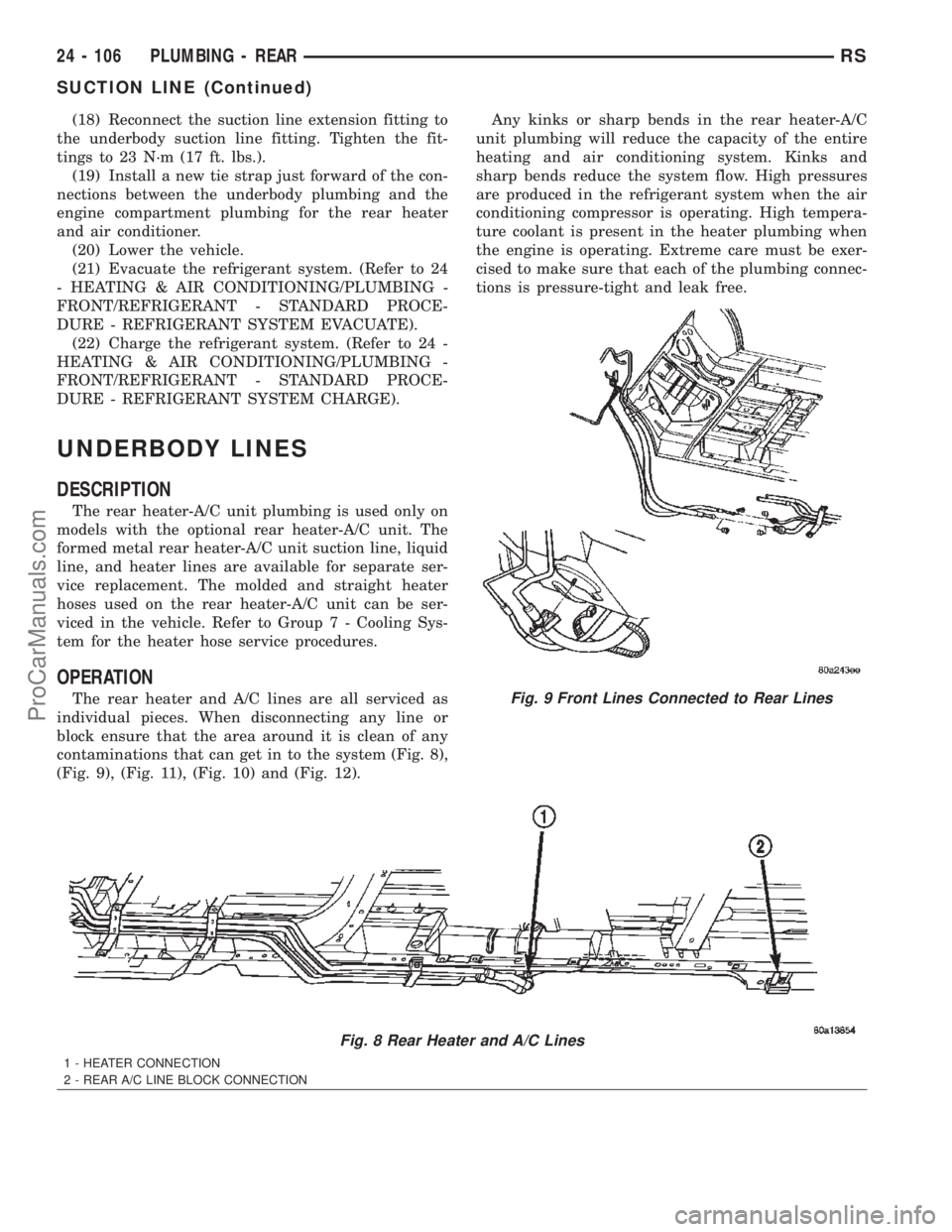
The rear heater and A/C lines are all serviced as
individual pieces. When disconnecting any line or
block ensure that the area around it is clean of any
contaminations that can get in to the system (Fig. 8),
(Fig. 9), (Fig. 11), (Fig. 10) and (Fig. 12).Any kinks or sharp bends in the rear heater-A/C
unit plumbing will reduce the capacity of the entire
heating and air conditioning system. Kinks and
sharp bends reduce the system flow. High pressures
are produced in the refrigerant system when the air
conditioning compressor is operating. High tempera-
ture coolant is present in the heater plumbing when
the engine is operating. Extreme care must be exer-
cised to make sure that each of the plumbing connec-
tions is pressure-tight and leak free.
Fig. 8 Rear Heater and A/C Lines
1 - HEATER CONNECTION
2 - REAR A/C LINE BLOCK CONNECTION
Fig. 9 Front Lines Connected to Rear Lines
24 - 106 PLUMBING - REARRS
SUCTION LINE (Continued)
ProCarManuals.com
Page 2350 of 2399
REMOVAL
REMOVAL - REAR HEATER LINES
(1) Raise and support vehicle.
(2) Pinch off rubber heater line hose.
(3) Disconnect quick connect fitting at C-pillar.
(4) Loosen one screw and remove the other screw
at each of the three brackets holding the front of the
line to the underbody.
(5) Lower rear of line and drain coolant into a
suitable container.
(6) Loosen hose clamps at front of line and remove
line from vehicle.
REMOVAL - REAR AIR CONDITIONING LINES
(1) Recover A/C system.
(2) Hoist and support vehicle.
(3) Loosen one screw and remove the other screw
at each of the three brackets holding the A/C lines to
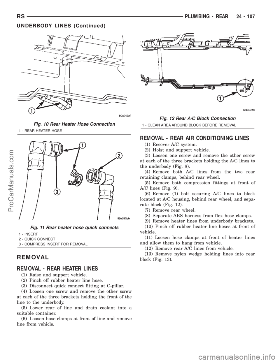
the underbody (Fig. 8).
(4) Remove both A/C lines from the two rear
retaining clamps, behind rear wheel.
(5) Remove both compression fittings at front of
A/C lines (Fig. 9).
(6) Remove (1) bolt securing A/C lines to block
located at A/C housing, behind rear wheel, and sepa-
rate block (Fig. 12).
(7) Remove rear wheel.
(8) Separate ABS harness from flex hose clamps.
(9) Remove heater lines from underbody brackets.
(10) Pinch off rubber heater line hoses at front of
vehicle.
(11) Loosen hose clamps at front of heater lines
and allow them to hang from vehicle.
(12) Remove rear A/C lines from vehicle.
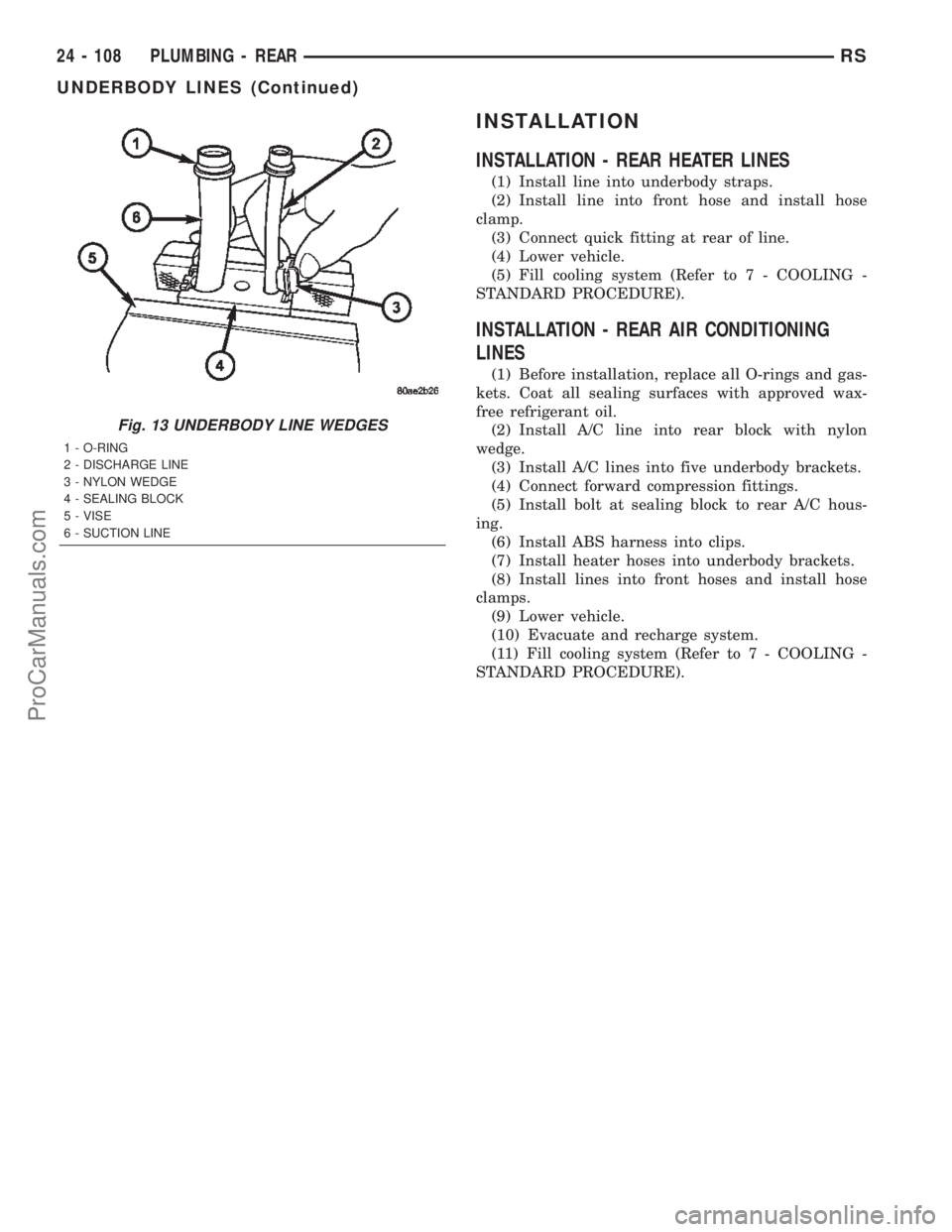
(13) Remove nylon wedge holding lines into rear
block (Fig. 13).
Fig. 10 Rear Heater Hose Connection
1 - REAR HEATER HOSE
Fig. 11 Rear heater hose quick connects
1 - INSERT
2 - QUICK CONNECT
3 - COMPRESS INSERT FOR REMOVAL
Fig. 12 Rear A/C Block Connection
1 - CLEAN AREA AROUND BLOCK BEFORE REMOVAL
RSPLUMBING - REAR24 - 107
UNDERBODY LINES (Continued)
ProCarManuals.com
Page 2351 of 2399
INSTALLATION
INSTALLATION - REAR HEATER LINES
(1) Install line into underbody straps.
(2) Install line into front hose and install hose
clamp.
(3) Connect quick fitting at rear of line.
(4) Lower vehicle.
(5) Fill cooling system (Refer to 7 - COOLING -
STANDARD PROCEDURE).
INSTALLATION - REAR AIR CONDITIONING
LINES
(1) Before installation, replace all O-rings and gas-
kets. Coat all sealing surfaces with approved wax-
free refrigerant oil.
(2) Install A/C line into rear block with nylon
wedge.
(3) Install A/C lines into five underbody brackets.
(4) Connect forward compression fittings.
(5) Install bolt at sealing block to rear A/C hous-
ing.
(6) Install ABS harness into clips.
(7) Install heater hoses into underbody brackets.
(8) Install lines into front hoses and install hose
clamps.
(9) Lower vehicle.
(10) Evacuate and recharge system.
(11) Fill cooling system (Refer to 7 - COOLING -
STANDARD PROCEDURE).
Fig. 13 UNDERBODY LINE WEDGES
1 - O-RING
2 - DISCHARGE LINE
3 - NYLON WEDGE
4 - SEALING BLOCK
5 - VISE
6 - SUCTION LINE
24 - 108 PLUMBING - REARRS
UNDERBODY LINES (Continued)
ProCarManuals.com
Page 2367 of 2399
chemical reaction takes place. This means the con-
centration of oxygen will be the same downstream as
upstream. The output voltage of the downstream
O2S copies the voltage of the upstream sensor. The
only difference is a time lag (seen by the PCM)
between the switching of the O2S's.
To monitor the system, the number of lean-to-rich
switches of upstream and downstream O2S's is
counted. The ratio of downstream switches to
upstream switches is used to determine whether the
catalyst is operating properly. An effective catalyst
will have fewer downstream switches than it has
upstream switches i.e., a ratio closer to zero. For a
totally ineffective catalyst, this ratio will be one-to-
one, indicating that no oxidation occurs in the device.
The system must be monitored so that when cata-
lyst efficiency deteriorates and exhaust emissions
increase to over the legal limit, the MIL (Check
Engine lamp) will be illuminated.
LEAK DETECTION PUMP MONITOR (if equipped)
The leak detection assembly incorporates two pri-
mary functions: it must detect a leak in the evapora-
tive system and seal the evaporative system so the
leak detection test can be run.
The primary components within the assembly are:
A three port solenoid that activates both of the func-
tions listed above; a pump which contains a switch,
two check valves, a spring/diaphragm, and a canister
vent valve (CVV) seal which contains a spring loaded
vent seal valve.
Immediately after a cold start, between predeter-
mined temperature thresholds limits, the three port
solenoid is briefly energized. This initializes the
pump by drawing air into the pump cavity and also
closes the vent seal. During non test conditions the
vent seal is held open by the pump diaphragm
assembly which pushes it open at the full travel posi-
tion. The vent seal will remain closed while the
pump is cycling due to the reed switch triggering of
the three port solenoid that prevents the diaphragm
assembly from reaching full travel. After the brief
initialization period, the solenoid is de-energized
allowing atmospheric pressure to enter the pump
cavity, thus permitting the spring to drive the dia-
phragm which forces air out of the pump cavity and
into the vent system. When the solenoid is energized
and de energized, the cycle is repeated creating flow
in typical diaphragm pump fashion. The pump is con-
trolled in 2 modes:
Pump Mode:The pump is cycled at a fixed rate to
achieve a rapid pressure build in order to shorten the
overall test length.
Test Mode:The solenoid is energized with a fixed
duration pulse. Subsequent fixed pulses occur when
the diaphragm reaches the Switch closure point.The spring in the pump is set so that the system
will achieve an equalized pressure of about 7.5º
water. The cycle rate of pump strokes is quite rapid
as the system begins to pump up to this pressure. As
the pressure increases, the cycle rate starts to drop
off. If there is no leak in the system, the pump would
eventually stop pumping at the equalized pressure. If
there is a leak, it will continue to pump at a rate rep-
resentative of the flow characteristic of the size of the
leak. From this information we can determine if the
leak is larger than the required detection limit (cur-
rently set at .020º orifice by CARB). If a leak is
revealed during the leak test portion of the test, the
test is terminated at the end of the test mode and no
further system checks will be performed.
The canister vent valve will unseal the system
after completion of the test sequence as the pump
diaphragm assembly moves to the full travel position.
Evaporative system functionality will be verified by
using the stricter evap purge flow monitor. At an
appropriate warm idle the LDP will be energized to
seal the canister vent. The purge flow will be clocked
up from some small value in an attempt to see a
shift in the 02 control system. If fuel vapor, indicated
by a shift in the 02 control, is present the test is
passed. If not, it is assumed that the purge system is
not functioning in some respect. The LDP is again
turned off and the test is ended.
Natural Vacuum Leak Detection (NVLD) (if equipped)
The Natural Vacuum Leak Detection (NVLD) sys-
tem is the next generation evaporative leak detection
system that will first be used on vehicles equipped
with the Next Generation Controller (NGC) starting
in 2002 M.Y. This new system replaces the leak
detection pump as the method of evaporative system
leak detection. This is to detect a leak equivalent to a
0.0209(0.5 mm) hole. This system has the capability
to detect holes of this size very dependably.
The basic leak detection theory employed with
NVLD is the9Gas Law9. This is to say that the pres-
sure in a sealed vessel will change if the temperature
of the gas in the vessel changes. The vessel will only
see this effect if it is indeed sealed. Even small leaks
will allow the pressure in the vessel to come to equi-
librium with the ambient pressure. In addition to the
detection of very small leaks, this system has the
capability of detecting medium as well as large evap-
orative system leaks.
A vent valve seals the canister vent during engine
off conditions. If the vapor system has a leak of less
than the failure threshold, the evaporative system
will be pulled into a vacuum, either due to the cool
down from operating temperature or diurnal ambient
temperature cycling. The diurnal effect is considered
one of the primary contributors to the leak determi-
25 - 8 EMISSIONS CONTROLRS
EMISSIONS CONTROL (Continued)
ProCarManuals.com
Page 2376 of 2399
PCV VALVE
DESCRIPTION
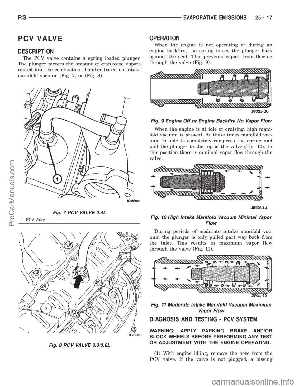
The PCV valve contains a spring loaded plunger.
The plunger meters the amount of crankcase vapors
routed into the combustion chamber based on intake
manifold vacuum (Fig. 7) or (Fig. 8).
OPERATION
When the engine is not operating or during an
engine backfire, the spring forces the plunger back
against the seat. This prevents vapors from flowing
through the valve (Fig. 9).
When the engine is at idle or cruising, high mani-
fold vacuum is present. At these times manifold vac-
uum is able to completely compress the spring and
pull the plunger to the top of the valve (Fig. 10). In
this position there is minimal vapor flow through the
valve.
During periods of moderate intake manifold vac-
uum the plunger is only pulled part way back from
the inlet. This results in maximum vapor flow
through the valve (Fig. 11).
DIAGNOSIS AND TESTING - PCV SYSTEM
WARNING: APPLY PARKING BRAKE AND/OR
BLOCK WHEELS BEFORE PERFORMING ANY TEST
OR ADJUSTMENT WITH THE ENGINE OPERATING.
(1) With engine idling, remove the hose from the
PCV valve. If the valve is not plugged, a hissing
Fig. 7 PCV VALVE 2.4L
1 - PCV Valve
Fig. 8 PCV VALVE 3.3/3.8L
Fig. 9 Engine Off or Engine Backfire No Vapor Flow
Fig. 10 High Intake Manifold Vacuum Minimal Vapor
Flow
Fig. 11 Moderate Intake Manifold Vacuum Maximum
Vapor Flow
RSEVAPORATIVE EMISSIONS25-17
ProCarManuals.com
Page 2382 of 2399
REMOVAL
REMOVAL - 2.4L
The EGR valve and Electrical EGR Transducer are
serviced as an assembly (Fig. 1).
(1) Disconnect vacuum tube from electric EGR
transducer. Inspect vacuum tube for damage.
(2) Remove electrical connector from solenoid.
(3) Remove EGR tube bolts from EGR valve.
(4) Remove EGR valve from cylinder head adaptor.
(5) Clean gasket surface and discard old gasket.
Check for any signs of leakage or cracked surfaces.
Repair or replace as necessary.
REMOVAL - 3.5L
(1) Disconnect the negative battery cable.
(2) Disconnect the fresh air makeup hose on rear
valve cover.
(3) Remove the air box bolt.
(4) Remove the hose clamp at throttle body.
(5) Unlatch 2 clamps for air box cover.
(6) Remove air box cover.
(7) Unlock the electrical connector.
(8) Disconnect the electrical connector from the
EGR valve.
(9) Remove the 2 bolts for the front EGR tube
(10) Remove the 2 bolts for the rear EGR tube
(11) Remove the 2 EGR valve mounting bolts.
(12) Remove the EGR valve.
INSTALLATION
INSTALLATION - 2.4L
The EGR valve and Electrical EGR Transducer are
serviced as an assembly (Fig. 1).
(1) Assemble EGR valve with new gasket onto the
cylinder head adaptor.
(2) Loose assemble the bolts from EGR valve to
EGR tube.
(3) Loose assemble the bolts from EGR valve to
cylinder head.
(4) Tighten bolts from EGR valve to cylinder head
to 22.8 N´m (200 25 in. lbs.) torque.
(5) Tighten bolts from EGR valve to EGR tube to
11.9 N´m (105 20 in. lbs.) torque.
(6) Reconnect vacuum hose and electrical connec-
tor to electrical EGR transducer.
INSTALLATION - 3.5L
(1) Install the EGR valve.
(2) Install the 2 bolts for the rear EGR tube
(3) Install the 2 bolts for the front EGR tube
(4) Tighten the EGR tube bolts.
(5) Tighten the EGR valve mounting bolts.
(6) Connect the electrical connector to the EGR
valve.
(7) Lock the electrical connector.
(8) Install air box cover.
(9) Latch 2 clamps for air box cover.
(10) Install the hose clamp at throttle body.
(11) Connect the fresh air makeup hose on rear
valve cover.
(12) Connect the negative battery cable.
RSEXHAUST GAS RECIRCULATION25-23
VALVE (Continued)
ProCarManuals.com