2002 CHRYSLER CARAVAN engine
[x] Cancel search: enginePage 1683 of 2399
OPERATION
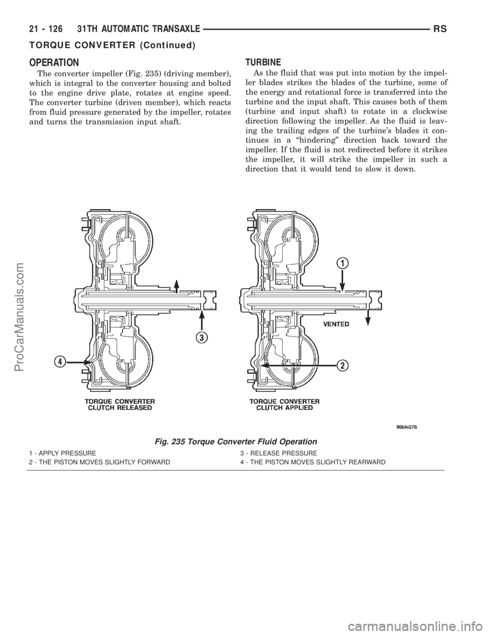
The converter impeller (Fig. 235) (driving member),
which is integral to the converter housing and bolted
to the engine drive plate, rotates at engine speed.
The converter turbine (driven member), which reacts
from fluid pressure generated by the impeller, rotates
and turns the transmission input shaft.
TURBINE
As the fluid that was put into motion by the impel-
ler blades strikes the blades of the turbine, some of
the energy and rotational force is transferred into the
turbine and the input shaft. This causes both of them
(turbine and input shaft) to rotate in a clockwise
direction following the impeller. As the fluid is leav-
ing the trailing edges of the turbine's blades it con-
tinues in a ªhinderingº direction back toward the
impeller. If the fluid is not redirected before it strikes
the impeller, it will strike the impeller in such a
direction that it would tend to slow it down.
Fig. 235 Torque Converter Fluid Operation
1 - APPLY PRESSURE 3 - RELEASE PRESSURE
2 - THE PISTON MOVES SLIGHTLY FORWARD 4 - THE PISTON MOVES SLIGHTLY REARWARD
21 - 126 31TH AUTOMATIC TRANSAXLERS
TORQUE CONVERTER (Continued)
ProCarManuals.com
Page 1684 of 2399
STATOR
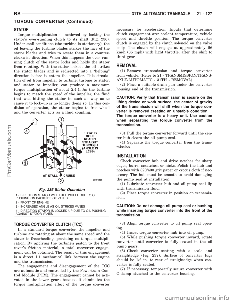
Torque multiplication is achieved by locking the
stator's over-running clutch to its shaft (Fig. 236).
Under stall conditions (the turbine is stationary), the
oil leaving the turbine blades strikes the face of the
stator blades and tries to rotate them in a counter-
clockwise direction. When this happens the over±run-
ning clutch of the stator locks and holds the stator
from rotating. With the stator locked, the oil strikes
the stator blades and is redirected into a ªhelpingº
direction before it enters the impeller. This circula-
tion of oil from impeller to turbine, turbine to stator,
and stator to impeller, can produce a maximum
torque multiplication of about 2.4:1. As the turbine
begins to match the speed of the impeller, the fluid
that was hitting the stator in such as way as to
cause it to lock±up is no longer doing so. In this con-
dition of operation, the stator begins to free wheel
and the converter acts as a fluid coupling.
TORQUE CONVERTER CLUTCH (TCC)
In a standard torque converter, the impeller and
turbine are rotating at about the same speed and the
stator is freewheeling, providing no torque multipli-
cation. By applying the turbine's piston to the front
cover's friction material, a total converter engage-
ment can be obtained. The result of this engagement
is a direct 1:1 mechanical link between the engine
and the transmission.
The engagement and disengagement of the TCC
are automatic and controlled by the Powertrain Con-
trol Module (PCM). The engagement cannot be acti-
vated in the lower gears because it eliminates the
torque multiplication effect of the torque converternecessary for acceleration. Inputs that determine
clutch engagement are: coolant temperature, vehicle
speed and throttle position. The torque converter
clutch is engaged by the clutch solenoid on the valve
body. The clutch will engage at approximately 56
km/h (35 mph) with light throttle, after the shift to
third gear.
REMOVAL
(1) Remove transmission and torque converter
from vehicle. (Refer to 21 - TRANSMISSION/TRANS-
AXLE/AUTOMATIC - 31TH - REMOVAL)
(2) Place a suitable drain pan under the converter
housing end of the transmission.
CAUTION: Verify that transmission is secure on the
lifting device or work surface, the center of gravity
of the transmission will shift when the torque con-
verter is removed creating an unstable condition.
The torque converter is a heavy unit. Use caution
when separating the torque converter from the
transmission.
(3) Pull the torque converter forward until the cen-
ter hub clears the oil pump seal.
(4) Separate the torque converter from the trans-
mission.
INSTALLATION
Check converter hub and drive notches for sharp
edges, burrs, scratches, or nicks. Polish the hub and
notches with 320/400 grit paper or crocus cloth if nec-
essary. The hub must be smooth to avoid damaging
the pump seal at installation.
(1) Lubricate converter hub and oil pump seal lip
with transmission fluid.
(2) Place torque converter in position on transmis-
sion.
CAUTION: Do not damage oil pump seal or bushing
while inserting torque converter into the front of the
transmission.
(3) Align torque converter to oil pump seal open-
ing.
(4) Insert torque converter hub into oil pump.
(5) While pushing torque converter inward, rotate
converter until converter is fully seated in the oil
pump gears.
(6) Check converter seating with a scale and
straightedge (Fig. 237). Surface of converter lugs
should be 1/2 in. to rear of straightedge when con-
verter is fully seated.
(7) If necessary, temporarily secure converter with
C-clamp attached to the converter housing.
Fig. 236 Stator Operation
1 - DIRECTION STATOR WILL FREE WHEEL DUE TO OIL
PUSHING ON BACKSIDE OF VANES
2 - FRONT OF ENGINE
3 - INCREASED ANGLE AS OIL STRIKES VANES
4 - DIRECTION STATOR IS LOCKED UP DUE TO OIL PUSHING
AGAINST STATOR VANES
RS31TH AUTOMATIC TRANSAXLE21 - 127
TORQUE CONVERTER (Continued)
ProCarManuals.com
Page 1721 of 2399
TRANSAXLE IDENTIFICATION
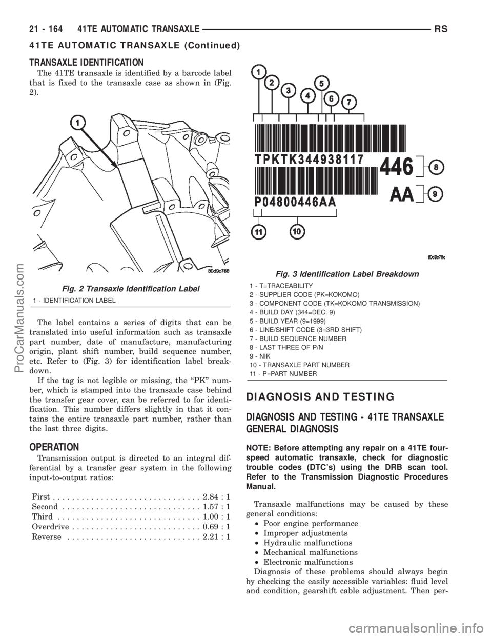
The 41TE transaxle is identified by a barcode label
that is fixed to the transaxle case as shown in (Fig.
2).
The label contains a series of digits that can be
translated into useful information such as transaxle
part number, date of manufacture, manufacturing
origin, plant shift number, build sequence number,
etc. Refer to (Fig. 3) for identification label break-
down.
If the tag is not legible or missing, the ªPKº num-
ber, which is stamped into the transaxle case behind
the transfer gear cover, can be referred to for identi-
fication. This number differs slightly in that it con-
tains the entire transaxle part number, rather than
the last three digits.
OPERATION
Transmission output is directed to an integral dif-
ferential by a transfer gear system in the following
input-to-output ratios:
First...............................2.84 : 1
Second.............................1.57 : 1
Third..............................1.00 : 1
Overdrive...........................0.69 : 1
Reverse............................2.21 : 1
DIAGNOSIS AND TESTING
DIAGNOSIS AND TESTING - 41TE TRANSAXLE
GENERAL DIAGNOSIS
NOTE: Before attempting any repair on a 41TE four-
speed automatic transaxle, check for diagnostic
trouble codes (DTC's) using the DRB scan tool.
Refer to the Transmission Diagnostic Procedures
Manual.
Transaxle malfunctions may be caused by these
general conditions:
²Poor engine performance
²Improper adjustments
²Hydraulic malfunctions
²Mechanical malfunctions
²Electronic malfunctions
Diagnosis of these problems should always begin
by checking the easily accessible variables: fluid level
and condition, gearshift cable adjustment. Then per-
Fig. 2 Transaxle Identification Label
1 - IDENTIFICATION LABEL
Fig. 3 Identification Label Breakdown
1 - T=TRACEABILITY
2 - SUPPLIER CODE (PK=KOKOMO)
3 - COMPONENT CODE (TK=KOKOMO TRANSMISSION)
4 - BUILD DAY (344=DEC. 9)
5 - BUILD YEAR (9=1999)
6 - LINE/SHIFT CODE (3=3RD SHIFT)
7 - BUILD SEQUENCE NUMBER
8 - LAST THREE OF P/N
9 - NIK
10 - TRANSAXLE PART NUMBER
11 - P=PART NUMBER
21 - 164 41TE AUTOMATIC TRANSAXLERS
41TE AUTOMATIC TRANSAXLE (Continued)
ProCarManuals.com
Page 1723 of 2399
Install an engine tachometer, raise vehicle on hoist
which allows front wheels to turn, and position
tachometer so it can be read.
Attach 300 psi gauge (C-3293SP) to port(s)
required for test(s) being conducted. Use adapter set
L-4559 to adapt gauge(s) to transaxle.
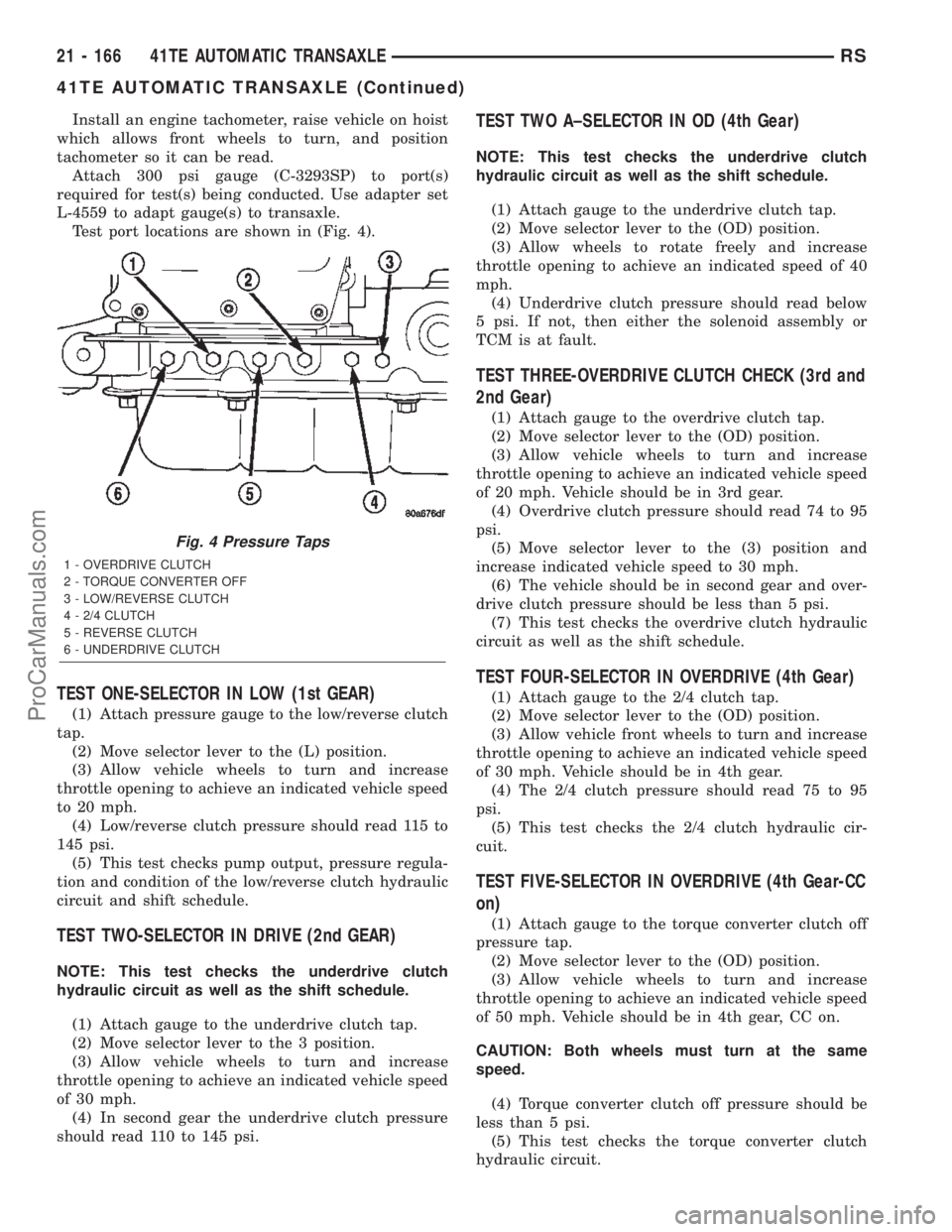
Test port locations are shown in (Fig. 4).
TEST ONE-SELECTOR IN LOW (1st GEAR)
(1) Attach pressure gauge to the low/reverse clutch
tap.
(2) Move selector lever to the (L) position.
(3) Allow vehicle wheels to turn and increase
throttle opening to achieve an indicated vehicle speed
to 20 mph.
(4) Low/reverse clutch pressure should read 115 to
145 psi.
(5) This test checks pump output, pressure regula-
tion and condition of the low/reverse clutch hydraulic
circuit and shift schedule.
TEST TWO-SELECTOR IN DRIVE (2nd GEAR)
NOTE: This test checks the underdrive clutch
hydraulic circuit as well as the shift schedule.
(1) Attach gauge to the underdrive clutch tap.
(2) Move selector lever to the 3 position.
(3) Allow vehicle wheels to turn and increase
throttle opening to achieve an indicated vehicle speed
of 30 mph.
(4) In second gear the underdrive clutch pressure
should read 110 to 145 psi.
TEST TWO A±SELECTOR IN OD (4th Gear)
NOTE: This test checks the underdrive clutch
hydraulic circuit as well as the shift schedule.
(1) Attach gauge to the underdrive clutch tap.
(2) Move selector lever to the (OD) position.
(3) Allow wheels to rotate freely and increase
throttle opening to achieve an indicated speed of 40
mph.
(4) Underdrive clutch pressure should read below
5 psi. If not, then either the solenoid assembly or
TCM is at fault.
TEST THREE-OVERDRIVE CLUTCH CHECK (3rd and
2nd Gear)
(1) Attach gauge to the overdrive clutch tap.
(2) Move selector lever to the (OD) position.
(3) Allow vehicle wheels to turn and increase
throttle opening to achieve an indicated vehicle speed
of 20 mph. Vehicle should be in 3rd gear.
(4) Overdrive clutch pressure should read 74 to 95
psi.
(5) Move selector lever to the (3) position and
increase indicated vehicle speed to 30 mph.
(6) The vehicle should be in second gear and over-
drive clutch pressure should be less than 5 psi.
(7) This test checks the overdrive clutch hydraulic
circuit as well as the shift schedule.
TEST FOUR-SELECTOR IN OVERDRIVE (4th Gear)
(1) Attach gauge to the 2/4 clutch tap.
(2) Move selector lever to the (OD) position.
(3) Allow vehicle front wheels to turn and increase
throttle opening to achieve an indicated vehicle speed
of 30 mph. Vehicle should be in 4th gear.
(4) The 2/4 clutch pressure should read 75 to 95
psi.
(5) This test checks the 2/4 clutch hydraulic cir-
cuit.
TEST FIVE-SELECTOR IN OVERDRIVE (4th Gear-CC
on)
(1) Attach gauge to the torque converter clutch off
pressure tap.
(2) Move selector lever to the (OD) position.
(3) Allow vehicle wheels to turn and increase
throttle opening to achieve an indicated vehicle speed
of 50 mph. Vehicle should be in 4th gear, CC on.
CAUTION: Both wheels must turn at the same
speed.
(4) Torque converter clutch off pressure should be
less than 5 psi.
(5) This test checks the torque converter clutch
hydraulic circuit.
Fig. 4 Pressure Taps
1 - OVERDRIVE CLUTCH
2 - TORQUE CONVERTER OFF
3 - LOW/REVERSE CLUTCH
4 - 2/4 CLUTCH
5 - REVERSE CLUTCH
6 - UNDERDRIVE CLUTCH
21 - 166 41TE AUTOMATIC TRANSAXLERS
41TE AUTOMATIC TRANSAXLE (Continued)
ProCarManuals.com
Page 1724 of 2399
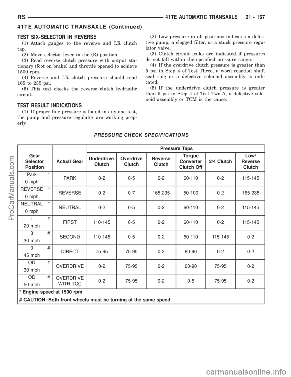
TEST SIX-SELECTOR IN REVERSE
(1) Attach gauges to the reverse and LR clutch
tap.
(2) Move selector lever to the (R) position.
(3) Read reverse clutch pressure with output sta-
tionary (foot on brake) and throttle opened to achieve
1500 rpm.
(4) Reverse and LR clutch pressure should read
165 to 235 psi.
(5) This test checks the reverse clutch hydraulic
circuit.
TEST RESULT INDICATIONS
(1) If proper line pressure is found in any one test,
the pump and pressure regulator are working prop-
erly.(2) Low pressure in all positions indicates a defec-
tive pump, a clogged filter, or a stuck pressure regu-
lator valve.
(3) Clutch circuit leaks are indicated if pressures
do not fall within the specified pressure range.
(4) If the overdrive clutch pressure is greater than
5 psi in Step 4 of Test Three, a worn reaction shaft
seal ring or a defective solenoid assembly is indi-
cated.
(5) If the underdrive clutch pressure is greater
than 5 psi in Step 4 of Test Two A, a defective sole-
noid assembly or TCM is the cause.
PRESSURE CHECK SPECIFICATIONS
Pressure Taps
Gear
Selector
PositionActual GearUnderdrive
ClutchOverdrive
ClutchReverse
ClutchTorque
Converter
Clutch Off2/4 ClutchLow/
Reverse
Clutch
Park *
PARK 0-2 0-5 0-2 60-110 0-2 115-145
0 mph
REVERSE *
REVERSE 0-2 0-7 165-235 50-100 0-2 165-235
0 mph
NEUTRAL *
NEUTRAL 0-2 0-5 0-2 60-110 0-2 115-145
0 mph
L#
FIRST 110-145 0-5 0-2 60-110 0-2 115-145
20 mph
3#
SECOND 110-145 0-5 0-2 60-110 115-145 0-2
30 mph
3#
DIRECT 75-95 75-95 0-2 60-90 0-2 0-2
45 mph
OD #
OVERDRIVE 0-2 75-95 0-2 60-90 75-95 0-2
30 mph
OD #
OVERDRIVE
WITH TCC0-2 75-95 0-2 0-5 75-95 0-2
50 mph
* Engine speed at 1500 rpm
# CAUTION: Both front wheels must be turning at the same speed.
RS41TE AUTOMATIC TRANSAXLE21 - 167
41TE AUTOMATIC TRANSAXLE (Continued)
ProCarManuals.com
Page 1725 of 2399
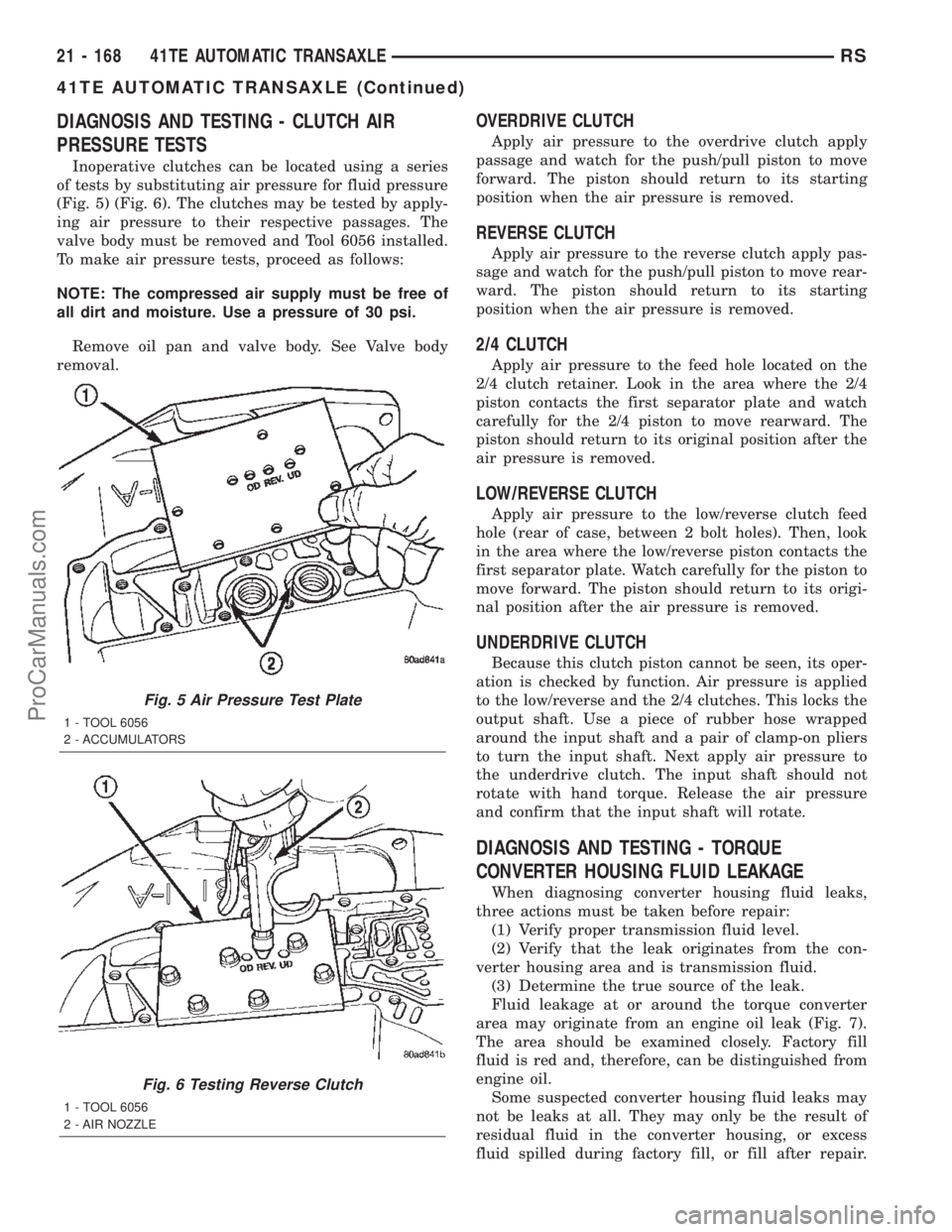
DIAGNOSIS AND TESTING - CLUTCH AIR
PRESSURE TESTS
Inoperative clutches can be located using a series
of tests by substituting air pressure for fluid pressure
(Fig. 5) (Fig. 6). The clutches may be tested by apply-
ing air pressure to their respective passages. The
valve body must be removed and Tool 6056 installed.
To make air pressure tests, proceed as follows:
NOTE: The compressed air supply must be free of
all dirt and moisture. Use a pressure of 30 psi.
Remove oil pan and valve body. See Valve body
removal.
OVERDRIVE CLUTCH
Apply air pressure to the overdrive clutch apply
passage and watch for the push/pull piston to move
forward. The piston should return to its starting
position when the air pressure is removed.
REVERSE CLUTCH
Apply air pressure to the reverse clutch apply pas-
sage and watch for the push/pull piston to move rear-
ward. The piston should return to its starting
position when the air pressure is removed.
2/4 CLUTCH
Apply air pressure to the feed hole located on the
2/4 clutch retainer. Look in the area where the 2/4
piston contacts the first separator plate and watch
carefully for the 2/4 piston to move rearward. The
piston should return to its original position after the
air pressure is removed.
LOW/REVERSE CLUTCH
Apply air pressure to the low/reverse clutch feed
hole (rear of case, between 2 bolt holes). Then, look
in the area where the low/reverse piston contacts the
first separator plate. Watch carefully for the piston to
move forward. The piston should return to its origi-
nal position after the air pressure is removed.
UNDERDRIVE CLUTCH
Because this clutch piston cannot be seen, its oper-
ation is checked by function. Air pressure is applied
to the low/reverse and the 2/4 clutches. This locks the
output shaft. Use a piece of rubber hose wrapped
around the input shaft and a pair of clamp-on pliers
to turn the input shaft. Next apply air pressure to
the underdrive clutch. The input shaft should not
rotate with hand torque. Release the air pressure
and confirm that the input shaft will rotate.
DIAGNOSIS AND TESTING - TORQUE
CONVERTER HOUSING FLUID LEAKAGE
When diagnosing converter housing fluid leaks,
three actions must be taken before repair:
(1) Verify proper transmission fluid level.
(2) Verify that the leak originates from the con-
verter housing area and is transmission fluid.
(3) Determine the true source of the leak.
Fluid leakage at or around the torque converter
area may originate from an engine oil leak (Fig. 7).
The area should be examined closely. Factory fill
fluid is red and, therefore, can be distinguished from
engine oil.
Some suspected converter housing fluid leaks may
not be leaks at all. They may only be the result of
residual fluid in the converter housing, or excess
fluid spilled during factory fill, or fill after repair.
Fig. 5 Air Pressure Test Plate
1 - TOOL 6056
2 - ACCUMULATORS
Fig. 6 Testing Reverse Clutch
1 - TOOL 6056
2 - AIR NOZZLE
21 - 168 41TE AUTOMATIC TRANSAXLERS
41TE AUTOMATIC TRANSAXLE (Continued)
ProCarManuals.com
Page 1728 of 2399
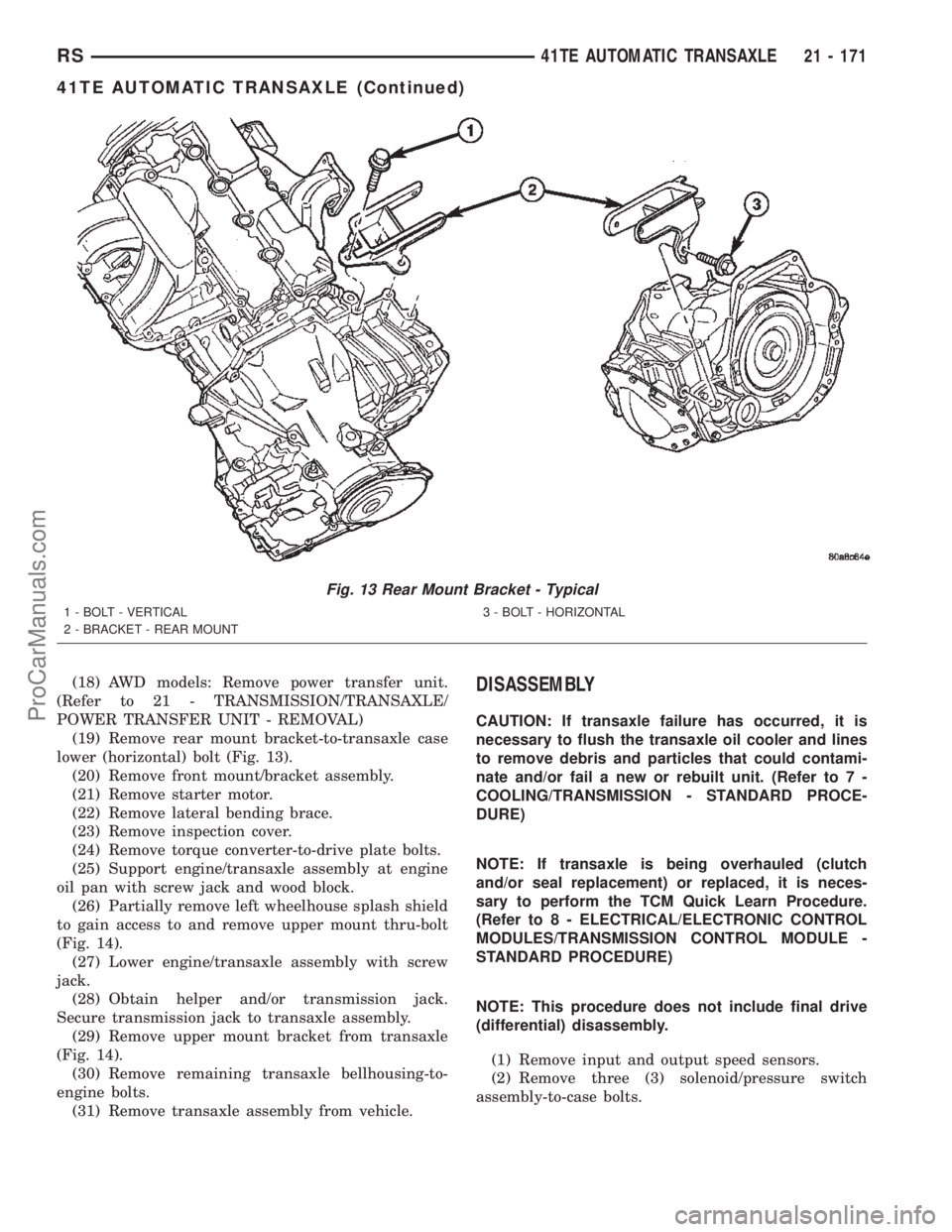
(18) AWD models: Remove power transfer unit.
(Refer to 21 - TRANSMISSION/TRANSAXLE/
POWER TRANSFER UNIT - REMOVAL)
(19) Remove rear mount bracket-to-transaxle case
lower (horizontal) bolt (Fig. 13).
(20) Remove front mount/bracket assembly.
(21) Remove starter motor.
(22) Remove lateral bending brace.
(23) Remove inspection cover.
(24) Remove torque converter-to-drive plate bolts.
(25) Support engine/transaxle assembly at engine
oil pan with screw jack and wood block.
(26) Partially remove left wheelhouse splash shield
to gain access to and remove upper mount thru-bolt
(Fig. 14).
(27) Lower engine/transaxle assembly with screw
jack.
(28) Obtain helper and/or transmission jack.
Secure transmission jack to transaxle assembly.
(29) Remove upper mount bracket from transaxle
(Fig. 14).
(30) Remove remaining transaxle bellhousing-to-
engine bolts.
(31) Remove transaxle assembly from vehicle.DISASSEMBLY
CAUTION: If transaxle failure has occurred, it is
necessary to flush the transaxle oil cooler and lines
to remove debris and particles that could contami-
nate and/or fail a new or rebuilt unit. (Refer to 7 -
COOLING/TRANSMISSION - STANDARD PROCE-
DURE)
NOTE: If transaxle is being overhauled (clutch
and/or seal replacement) or replaced, it is neces-
sary to perform the TCM Quick Learn Procedure.
(Refer to 8 - ELECTRICAL/ELECTRONIC CONTROL
MODULES/TRANSMISSION CONTROL MODULE -
STANDARD PROCEDURE)
NOTE: This procedure does not include final drive
(differential) disassembly.
(1) Remove input and output speed sensors.
(2) Remove three (3) solenoid/pressure switch
assembly-to-case bolts.
Fig. 13 Rear Mount Bracket - Typical
1 - BOLT - VERTICAL
2 - BRACKET - REAR MOUNT3 - BOLT - HORIZONTAL
RS41TE AUTOMATIC TRANSAXLE21 - 171
41TE AUTOMATIC TRANSAXLE (Continued)
ProCarManuals.com
Page 1730 of 2399
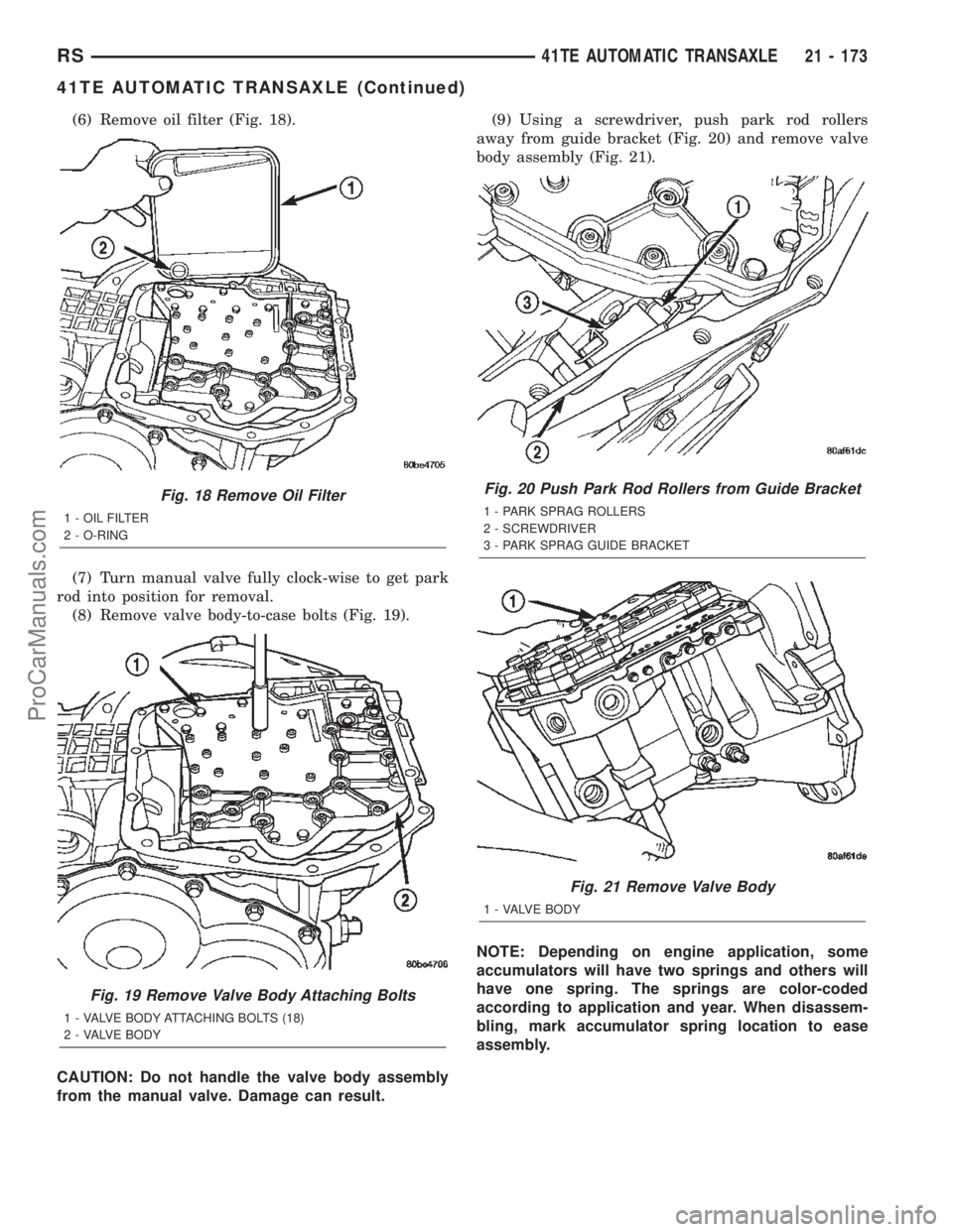
(6) Remove oil filter (Fig. 18).
(7) Turn manual valve fully clock-wise to get park
rod into position for removal.
(8) Remove valve body-to-case bolts (Fig. 19).
CAUTION: Do not handle the valve body assembly
from the manual valve. Damage can result.(9) Using a screwdriver, push park rod rollers
away from guide bracket (Fig. 20) and remove valve
body assembly (Fig. 21).
NOTE: Depending on engine application, some
accumulators will have two springs and others will
have one spring. The springs are color-coded
according to application and year. When disassem-
bling, mark accumulator spring location to ease
assembly.
Fig. 18 Remove Oil Filter
1 - OIL FILTER
2 - O-RING
Fig. 19 Remove Valve Body Attaching Bolts
1 - VALVE BODY ATTACHING BOLTS (18)
2 - VALVE BODY
Fig. 20 Push Park Rod Rollers from Guide Bracket
1 - PARK SPRAG ROLLERS
2 - SCREWDRIVER
3 - PARK SPRAG GUIDE BRACKET
Fig. 21 Remove Valve Body
1 - VALVE BODY
RS41TE AUTOMATIC TRANSAXLE21 - 173
41TE AUTOMATIC TRANSAXLE (Continued)
ProCarManuals.com