2002 CHRYSLER CARAVAN key battery
[x] Cancel search: key batteryPage 1480 of 2399
age will be higher at colder temperatures and is
gradually reduced at warmer temperatures.
The battery temperature information is also used
for OBD II diagnostics. Certain faults and OBD II
monitors are either enabled or disabled depending
upon the battery temperature sensor input (example:
disable purge, enable LDP). Most OBD II monitors
are disabled below 20ÉF.
MAP SENSOR
DESCRIPTION
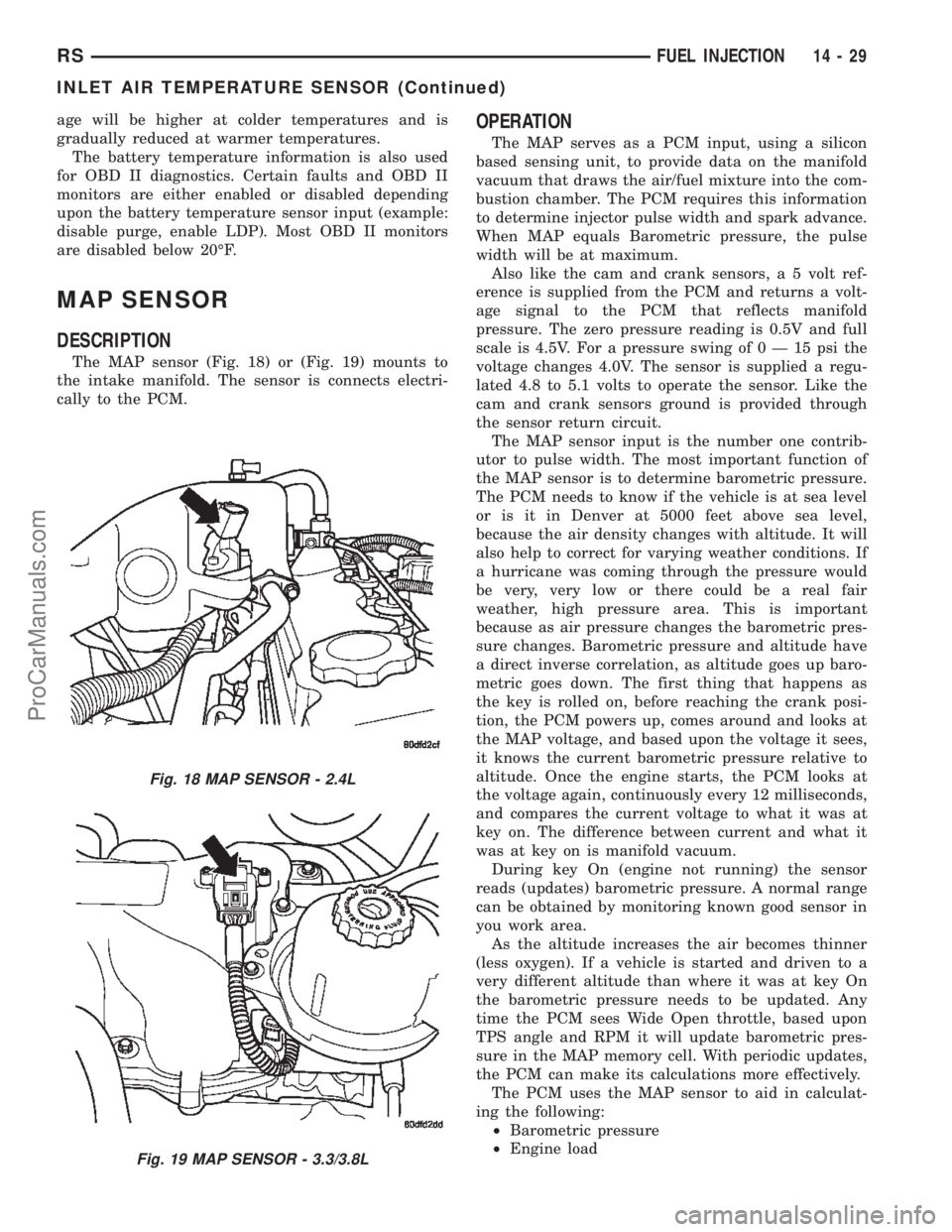
The MAP sensor (Fig. 18) or (Fig. 19) mounts to
the intake manifold. The sensor is connects electri-
cally to the PCM.
OPERATION
The MAP serves as a PCM input, using a silicon
based sensing unit, to provide data on the manifold
vacuum that draws the air/fuel mixture into the com-
bustion chamber. The PCM requires this information
to determine injector pulse width and spark advance.
When MAP equals Barometric pressure, the pulse
width will be at maximum.
Also like the cam and crank sensors, a 5 volt ref-
erence is supplied from the PCM and returns a volt-
age signal to the PCM that reflects manifold
pressure. The zero pressure reading is 0.5V and full
scale is 4.5V. For a pressure swing of0Ð15psithe
voltage changes 4.0V. The sensor is supplied a regu-
lated 4.8 to 5.1 volts to operate the sensor. Like the
cam and crank sensors ground is provided through
the sensor return circuit.
The MAP sensor input is the number one contrib-
utor to pulse width. The most important function of
the MAP sensor is to determine barometric pressure.
The PCM needs to know if the vehicle is at sea level
or is it in Denver at 5000 feet above sea level,
because the air density changes with altitude. It will
also help to correct for varying weather conditions. If
a hurricane was coming through the pressure would
be very, very low or there could be a real fair
weather, high pressure area. This is important
because as air pressure changes the barometric pres-
sure changes. Barometric pressure and altitude have
a direct inverse correlation, as altitude goes up baro-
metric goes down. The first thing that happens as
the key is rolled on, before reaching the crank posi-
tion, the PCM powers up, comes around and looks at
the MAP voltage, and based upon the voltage it sees,
it knows the current barometric pressure relative to
altitude. Once the engine starts, the PCM looks at
the voltage again, continuously every 12 milliseconds,
and compares the current voltage to what it was at
key on. The difference between current and what it
was at key on is manifold vacuum.
During key On (engine not running) the sensor
reads (updates) barometric pressure. A normal range
can be obtained by monitoring known good sensor in
you work area.
As the altitude increases the air becomes thinner
(less oxygen). If a vehicle is started and driven to a
very different altitude than where it was at key On
the barometric pressure needs to be updated. Any
time the PCM sees Wide Open throttle, based upon
TPS angle and RPM it will update barometric pres-
sure in the MAP memory cell. With periodic updates,
the PCM can make its calculations more effectively.
The PCM uses the MAP sensor to aid in calculat-
ing the following:
²Barometric pressure
²Engine load
Fig. 18 MAP SENSOR - 2.4L
Fig. 19 MAP SENSOR - 3.3/3.8L
RSFUEL INJECTION14-29
INLET AIR TEMPERATURE SENSOR (Continued)
ProCarManuals.com
Page 1497 of 2399
(6) Using special tool VM.1055 (Fig. 7), torque
injection pump sprocket retaining nut to 88.3N´m.
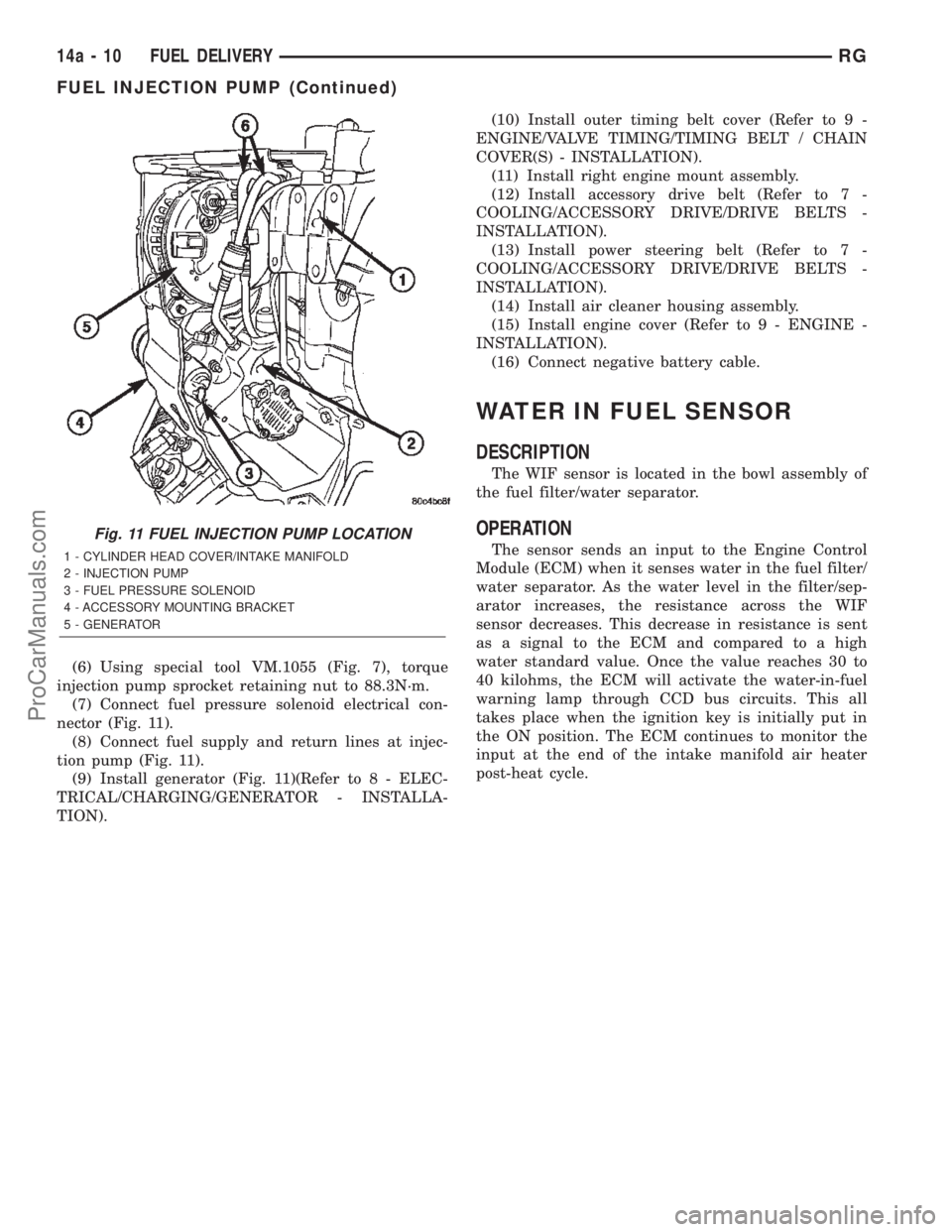
(7) Connect fuel pressure solenoid electrical con-
nector (Fig. 11).
(8) Connect fuel supply and return lines at injec-
tion pump (Fig. 11).
(9) Install generator (Fig. 11)(Refer to 8 - ELEC-
TRICAL/CHARGING/GENERATOR - INSTALLA-
TION).(10) Install outer timing belt cover (Refer to 9 -
ENGINE/VALVE TIMING/TIMING BELT / CHAIN
COVER(S) - INSTALLATION).
(11) Install right engine mount assembly.
(12) Install accessory drive belt (Refer to 7 -
COOLING/ACCESSORY DRIVE/DRIVE BELTS -
INSTALLATION).
(13) Install power steering belt (Refer to 7 -
COOLING/ACCESSORY DRIVE/DRIVE BELTS -
INSTALLATION).
(14) Install air cleaner housing assembly.
(15) Install engine cover (Refer to 9 - ENGINE -
INSTALLATION).
(16) Connect negative battery cable.
WATER IN FUEL SENSOR
DESCRIPTION
The WIF sensor is located in the bowl assembly of
the fuel filter/water separator.
OPERATION
The sensor sends an input to the Engine Control
Module (ECM) when it senses water in the fuel filter/
water separator. As the water level in the filter/sep-
arator increases, the resistance across the WIF
sensor decreases. This decrease in resistance is sent
as a signal to the ECM and compared to a high
water standard value. Once the value reaches 30 to
40 kilohms, the ECM will activate the water-in-fuel
warning lamp through CCD bus circuits. This all
takes place when the ignition key is initially put in
the ON position. The ECM continues to monitor the
input at the end of the intake manifold air heater
post-heat cycle.
Fig. 11 FUEL INJECTION PUMP LOCATION
1 - CYLINDER HEAD COVER/INTAKE MANIFOLD
2 - INJECTION PUMP
3 - FUEL PRESSURE SOLENOID
4 - ACCESSORY MOUNTING BRACKET
5 - GENERATOR
14a - 10 FUEL DELIVERYRG
FUEL INJECTION PUMP (Continued)
ProCarManuals.com
Page 1513 of 2399
COLUMN
TABLE OF CONTENTS
page page
COLUMN
DESCRIPTION - STEERING COLUMN.......10
WARNING
WARNINGS AND CAUTIONS.............10
DIAGNOSIS AND TESTING - STEERING
COLUMN............................12
REMOVAL.............................12
INSTALLATION.........................13
SPECIFICATIONS
COLUMN TORQUE....................14
IGNITION SWITCH
REMOVAL.............................15
INSTALLATION.........................16
LOCK CYLINDER HOUSING
DESCRIPTION - IGNITION INTERLOCK......17
REMOVAL.............................17INSTALLATION.........................20
KEY/LOCK CYLINDER
DESCRIPTION.........................21
OPERATION...........................21
REMOVAL.............................22
INSTALLATION.........................22
GEAR SHIFT LEVER
REMOVAL.............................22
INSTALLATION.........................22
SHROUD
REMOVAL.............................23
INSTALLATION.........................23
STEERING WHEEL
REMOVAL.............................23
INSTALLATION.........................25
COLUMN
DESCRIPTION - STEERING COLUMN
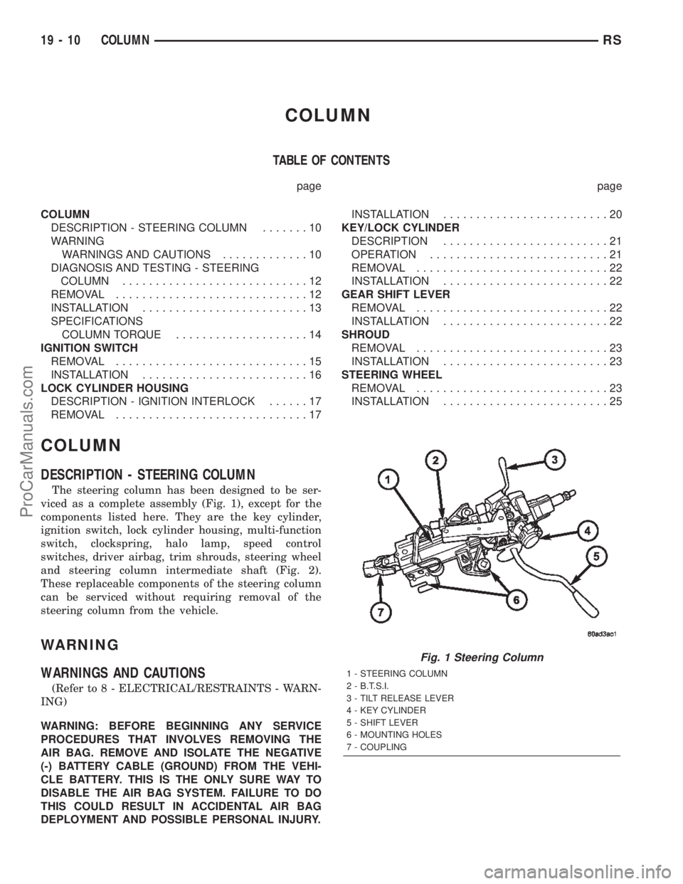
The steering column has been designed to be ser-
viced as a complete assembly (Fig. 1), except for the
components listed here. They are the key cylinder,
ignition switch, lock cylinder housing, multi-function
switch, clockspring, halo lamp, speed control
switches, driver airbag, trim shrouds, steering wheel
and steering column intermediate shaft (Fig. 2).
These replaceable components of the steering column
can be serviced without requiring removal of the
steering column from the vehicle.
WARNING
WARNINGS AND CAUTIONS
(Refer to 8 - ELECTRICAL/RESTRAINTS - WARN-
ING)
WARNING: BEFORE BEGINNING ANY SERVICE
PROCEDURES THAT INVOLVES REMOVING THE
AIR BAG. REMOVE AND ISOLATE THE NEGATIVE
(-) BATTERY CABLE (GROUND) FROM THE VEHI-
CLE BATTERY. THIS IS THE ONLY SURE WAY TO
DISABLE THE AIR BAG SYSTEM. FAILURE TO DO
THIS COULD RESULT IN ACCIDENTAL AIR BAG
DEPLOYMENT AND POSSIBLE PERSONAL INJURY.
Fig. 1 Steering Column
1 - STEERING COLUMN
2 - B.T.S.I.
3 - TILT RELEASE LEVER
4 - KEY CYLINDER
5 - SHIFT LEVER
6 - MOUNTING HOLES
7 - COUPLING
19 - 10 COLUMNRS
ProCarManuals.com
Page 1520 of 2399
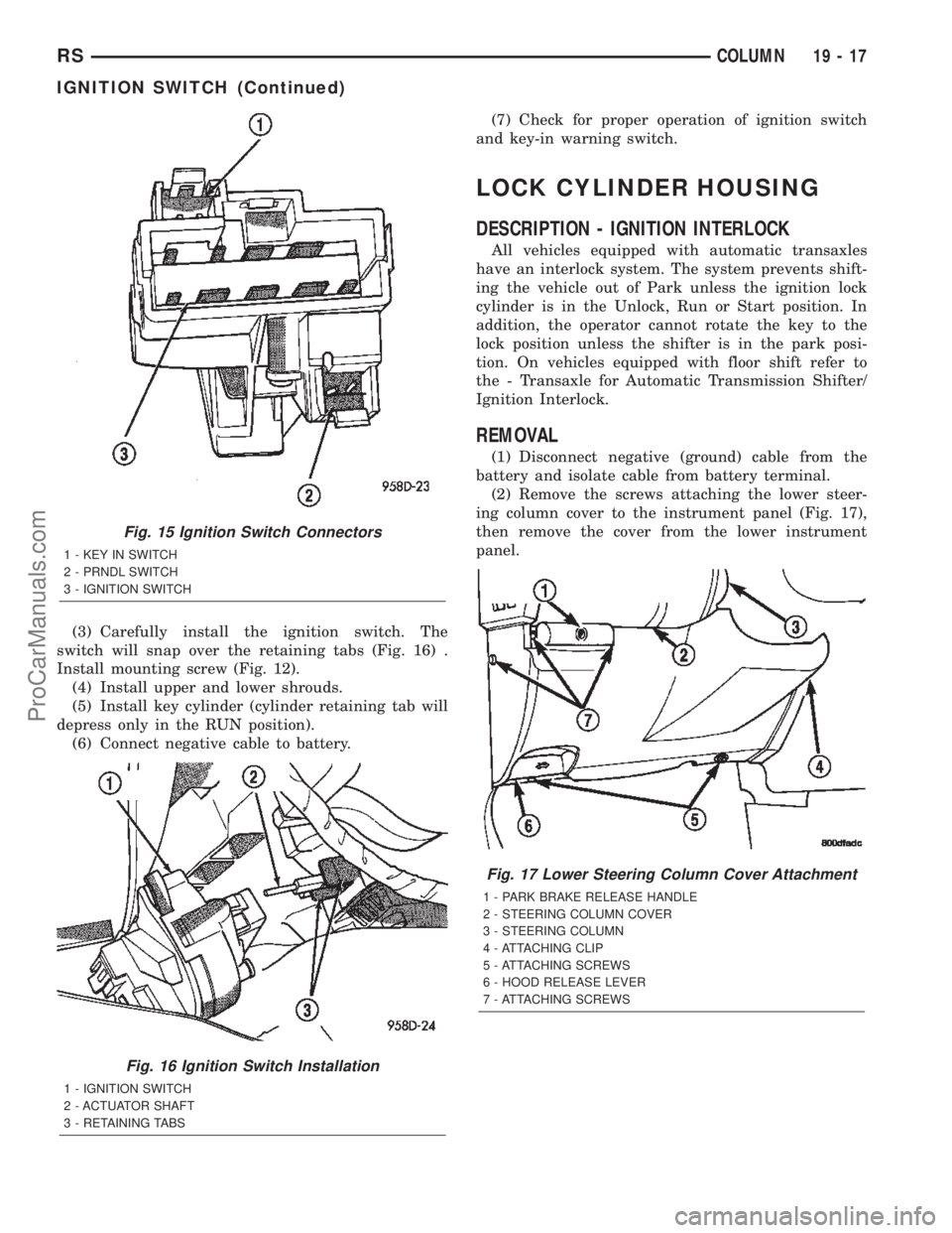
(3) Carefully install the ignition switch. The
switch will snap over the retaining tabs (Fig. 16) .
Install mounting screw (Fig. 12).
(4) Install upper and lower shrouds.
(5) Install key cylinder (cylinder retaining tab will
depress only in the RUN position).
(6) Connect negative cable to battery.(7) Check for proper operation of ignition switch
and key-in warning switch.
LOCK CYLINDER HOUSING
DESCRIPTION - IGNITION INTERLOCK
All vehicles equipped with automatic transaxles
have an interlock system. The system prevents shift-
ing the vehicle out of Park unless the ignition lock
cylinder is in the Unlock, Run or Start position. In
addition, the operator cannot rotate the key to the
lock position unless the shifter is in the park posi-
tion. On vehicles equipped with floor shift refer to
the - Transaxle for Automatic Transmission Shifter/
Ignition Interlock.
REMOVAL
(1) Disconnect negative (ground) cable from the
battery and isolate cable from battery terminal.
(2) Remove the screws attaching the lower steer-
ing column cover to the instrument panel (Fig. 17),
then remove the cover from the lower instrument
panel.
Fig. 15 Ignition Switch Connectors
1 - KEY IN SWITCH
2 - PRNDL SWITCH
3 - IGNITION SWITCH
Fig. 16 Ignition Switch Installation
1 - IGNITION SWITCH
2 - ACTUATOR SHAFT
3 - RETAINING TABS
Fig. 17 Lower Steering Column Cover Attachment
1 - PARK BRAKE RELEASE HANDLE
2 - STEERING COLUMN COVER
3 - STEERING COLUMN
4 - ATTACHING CLIP
5 - ATTACHING SCREWS
6 - HOOD RELEASE LEVER
7 - ATTACHING SCREWS
RSCOLUMN19-17
IGNITION SWITCH (Continued)
ProCarManuals.com
Page 1524 of 2399
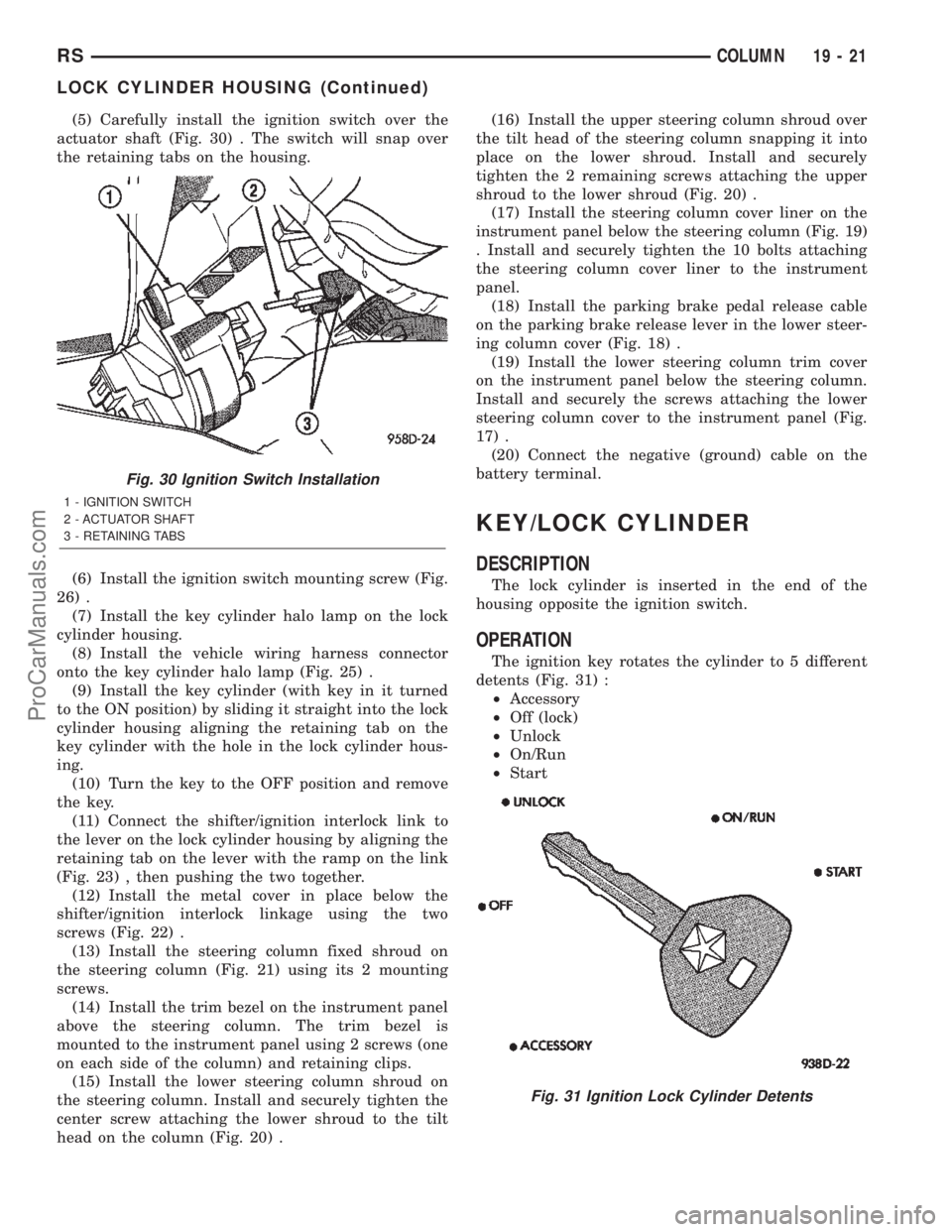
(5) Carefully install the ignition switch over the
actuator shaft (Fig. 30) . The switch will snap over
the retaining tabs on the housing.
(6) Install the ignition switch mounting screw (Fig.
26) .
(7) Install the key cylinder halo lamp on the lock
cylinder housing.
(8) Install the vehicle wiring harness connector
onto the key cylinder halo lamp (Fig. 25) .
(9) Install the key cylinder (with key in it turned
to the ON position) by sliding it straight into the lock
cylinder housing aligning the retaining tab on the
key cylinder with the hole in the lock cylinder hous-
ing.
(10) Turn the key to the OFF position and remove
the key.
(11) Connect the shifter/ignition interlock link to
the lever on the lock cylinder housing by aligning the
retaining tab on the lever with the ramp on the link
(Fig. 23) , then pushing the two together.
(12) Install the metal cover in place below the
shifter/ignition interlock linkage using the two
screws (Fig. 22) .
(13) Install the steering column fixed shroud on
the steering column (Fig. 21) using its 2 mounting
screws.
(14) Install the trim bezel on the instrument panel
above the steering column. The trim bezel is
mounted to the instrument panel using 2 screws (one
on each side of the column) and retaining clips.
(15) Install the lower steering column shroud on
the steering column. Install and securely tighten the
center screw attaching the lower shroud to the tilt
head on the column (Fig. 20) .(16) Install the upper steering column shroud over
the tilt head of the steering column snapping it into
place on the lower shroud. Install and securely
tighten the 2 remaining screws attaching the upper
shroud to the lower shroud (Fig. 20) .
(17) Install the steering column cover liner on the
instrument panel below the steering column (Fig. 19)
. Install and securely tighten the 10 bolts attaching
the steering column cover liner to the instrument
panel.
(18) Install the parking brake pedal release cable
on the parking brake release lever in the lower steer-
ing column cover (Fig. 18) .
(19) Install the lower steering column trim cover
on the instrument panel below the steering column.
Install and securely the screws attaching the lower
steering column cover to the instrument panel (Fig.
17) .
(20) Connect the negative (ground) cable on the
battery terminal.
KEY/LOCK CYLINDER
DESCRIPTION
The lock cylinder is inserted in the end of the
housing opposite the ignition switch.
OPERATION
The ignition key rotates the cylinder to 5 different
detents (Fig. 31) :
²Accessory
²Off (lock)
²Unlock
²On/Run
²Start
Fig. 30 Ignition Switch Installation
1 - IGNITION SWITCH
2 - ACTUATOR SHAFT
3 - RETAINING TABS
Fig. 31 Ignition Lock Cylinder Detents
RSCOLUMN19-21
LOCK CYLINDER HOUSING (Continued)
ProCarManuals.com
Page 1525 of 2399
REMOVAL
(1) Disconnect negative cable from battery.
(2) Remove steering column cover retaining
screws.
(3) Remove screws holding steering column
shrouds and remove lower shroud.
(4) Place key cylinder in RUN position. Depress
lock cylinder retaining tab on the bottom of the lock
housing and remove key cylinder.
INSTALLATION
(1) Install key in lock cylinder. Turn key to run
position (retaining tab on lock cylinder can be
depressed).
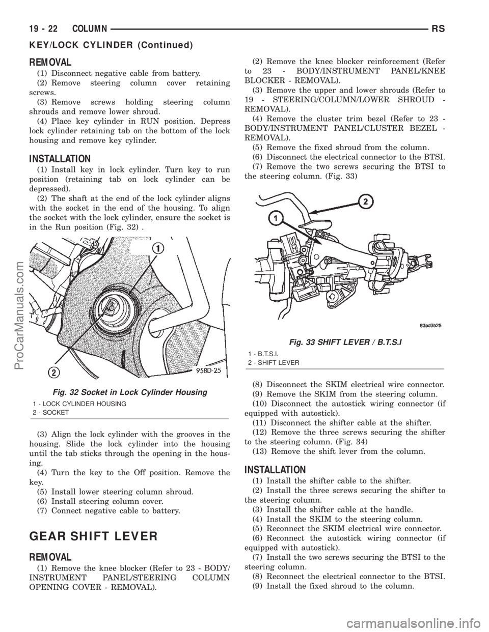
(2) The shaft at the end of the lock cylinder aligns
with the socket in the end of the housing. To align
the socket with the lock cylinder, ensure the socket is
in the Run position (Fig. 32) .
(3) Align the lock cylinder with the grooves in the
housing. Slide the lock cylinder into the housing
until the tab sticks through the opening in the hous-
ing.
(4) Turn the key to the Off position. Remove the
key.
(5) Install lower steering column shroud.
(6) Install steering column cover.
(7) Connect negative cable to battery.
GEAR SHIFT LEVER
REMOVAL
(1) Remove the knee blocker (Refer to 23 - BODY/
INSTRUMENT PANEL/STEERING COLUMN
OPENING COVER - REMOVAL).(2) Remove the knee blocker reinforcement (Refer
to 23 - BODY/INSTRUMENT PANEL/KNEE
BLOCKER - REMOVAL).
(3) Remove the upper and lower shrouds (Refer to
19 - STEERING/COLUMN/LOWER SHROUD -
REMOVAL).
(4) Remove the cluster trim bezel (Refer to 23 -
BODY/INSTRUMENT PANEL/CLUSTER BEZEL -
REMOVAL).
(5) Remove the fixed shroud from the column.
(6) Disconnect the electrical connector to the BTSI.
(7) Remove the two screws securing the BTSI to
the steering column. (Fig. 33)
(8) Disconnect the SKIM electrical wire connector.
(9) Remove the SKIM from the steering column.
(10) Disconnect the autostick wiring connector (if
equipped with autostick).
(11) Disconnect the shifter cable at the shifter.
(12) Remove the three screws securing the shifter
to the steering column. (Fig. 34)
(13) Remove the shift lever from the column.
INSTALLATION
(1) Install the shifter cable to the shifter.
(2) Install the three screws securing the shifter to
the steering column.
(3) Install the shifter cable at the handle.
(4) Install the SKIM to the steering column.
(5) Reconnect the SKIM electrical wire connector.
(6) Reconnect the autostick wiring connector (if
equipped with autostick).
(7) Install the two screws securing the BTSI to the
steering column.
(8) Reconnect the electrical connector to the BTSI.
(9) Install the fixed shroud to the column.
Fig. 32 Socket in Lock Cylinder Housing
1 - LOCK CYLINDER HOUSING
2 - SOCKET
Fig. 33 SHIFT LEVER / B.T.S.I
1 - B.T.S.I.
2 - SHIFT LEVER
19 - 22 COLUMNRS
KEY/LOCK CYLINDER (Continued)
ProCarManuals.com
Page 1672 of 2399
ASSEMBLY
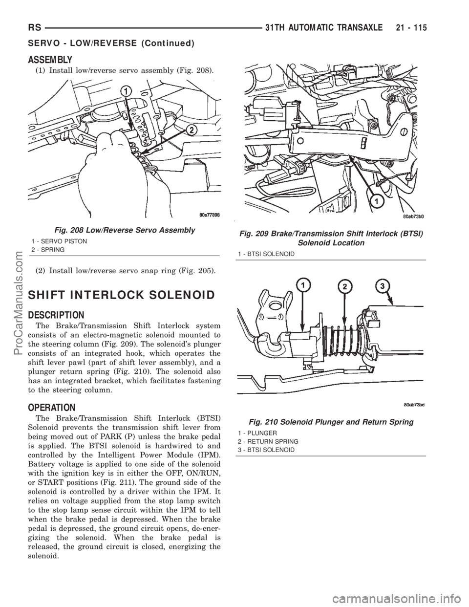
(1) Install low/reverse servo assembly (Fig. 208).
(2) Install low/reverse servo snap ring (Fig. 205).
SHIFT INTERLOCK SOLENOID
DESCRIPTION
The Brake/Transmission Shift Interlock system
consists of an electro-magnetic solenoid mounted to
the steering column (Fig. 209). The solenoid's plunger
consists of an integrated hook, which operates the
shift lever pawl (part of shift lever assembly), and a
plunger return spring (Fig. 210). The solenoid also
has an integrated bracket, which facilitates fastening
to the steering column.
OPERATION
The Brake/Transmission Shift Interlock (BTSI)
Solenoid prevents the transmission shift lever from
being moved out of PARK (P) unless the brake pedal
is applied. The BTSI solenoid is hardwired to and
controlled by the Intelligent Power Module (IPM).
Battery voltage is applied to one side of the solenoid
with the ignition key is in either the OFF, ON/RUN,
or START positions (Fig. 211). The ground side of the
solenoid is controlled by a driver within the IPM. It
relies on voltage supplied from the stop lamp switch
to the stop lamp sense circuit within the IPM to tell
when the brake pedal is depressed. When the brake
pedal is depressed, the ground circuit opens, de-ener-
gizing the solenoid. When the brake pedal is
released, the ground circuit is closed, energizing the
solenoid.
Fig. 208 Low/Reverse Servo Assembly
1 - SERVO PISTON
2 - SPRINGFig. 209 Brake/Transmission Shift Interlock (BTSI)
Solenoid Location
1 - BTSI SOLENOID
Fig. 210 Solenoid Plunger and Return Spring
1 - PLUNGER
2 - RETURN SPRING
3 - BTSI SOLENOID
RS31TH AUTOMATIC TRANSAXLE21 - 115
SERVO - LOW/REVERSE (Continued)
ProCarManuals.com
Page 1674 of 2399
DIAGNOSIS AND TESTING - BRAKE/
TRANSMISSION SHIFT INTERLOCK SOLENOID
For intended BTSI system operation, refer to the
following chart:
ACTION EXPECTED RESPONSE
1. Turn key to the9OFF9
position.1. Shifter CAN be shifted
out of park with brake
pedal applied.
2. Turn key to the
9ON/RUN9position.2. Shifter CANNOT be
shifted out of park.
3. Turn key to the
9ON/RUN9position and
depress the brake pedal.3. Shifter CAN be shifted
out of park.
4. Leave shifter in any
gear and try to return key
to the9LOCK9or9ACC9
position.4. Key cannot be
returned to the9LOCK9or
9ACC9position.
5. Return shifter to
9PARK9and try to remove
the key.5. Key can be removed
(after returning to9LOCK9
position).
6. With the key removed,
try to shift out of9PARK9.6. Shifter cannot be
shifted out of9PARK9.
NOTE: Any failure to meet these expected
responses requires system repair. Refer to the
appropriate Diagnostic Information.
REMOVAL
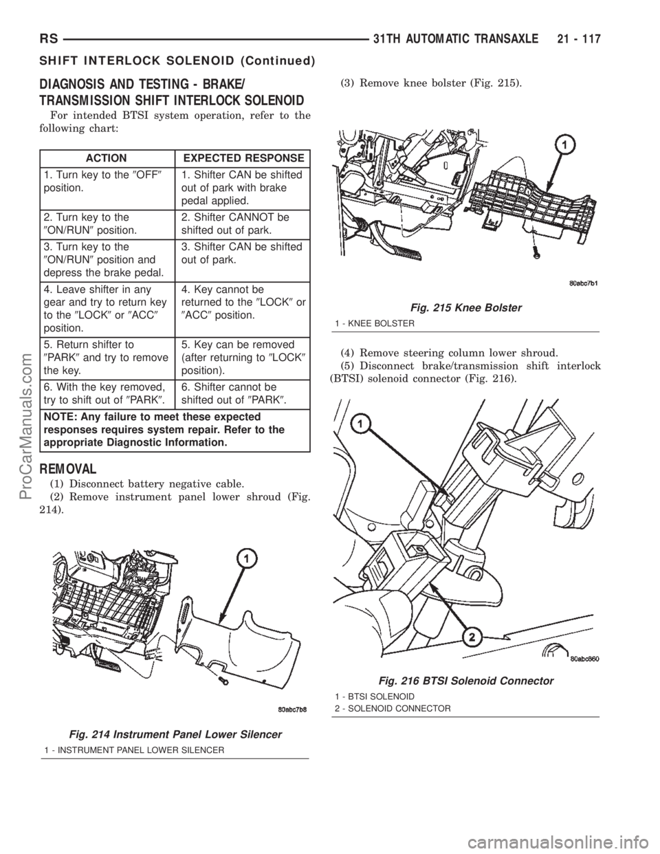
(1) Disconnect battery negative cable.
(2) Remove instrument panel lower shroud (Fig.
214).(3) Remove knee bolster (Fig. 215).
(4) Remove steering column lower shroud.
(5) Disconnect brake/transmission shift interlock
(BTSI) solenoid connector (Fig. 216).
Fig. 214 Instrument Panel Lower Silencer
1 - INSTRUMENT PANEL LOWER SILENCER
Fig. 215 Knee Bolster
1 - KNEE BOLSTER
Fig. 216 BTSI Solenoid Connector
1 - BTSI SOLENOID
2 - SOLENOID CONNECTOR
RS31TH AUTOMATIC TRANSAXLE21 - 117
SHIFT INTERLOCK SOLENOID (Continued)
ProCarManuals.com