2002 CHRYSLER CARAVAN differential
[x] Cancel search: differentialPage 1581 of 2399
ries the governor and parking sprag. An integral heli-
cal gear on the transfer shaft drives the differential
ring gear.
OPERATION
Transmission output is directed to an integral dif-
ferential by a transfer gear system in the following
input-to-output ratios:
FIRST 2.69:1
SECOND 1.55:1
THIRD 1.00:1
REVERSE 2.10:1
DIAGNOSIS AND TESTING
DIAGNOSIS AND TESTING - PRELIMINARY
DIAGNOSIS
Automatic transaxle malfunctions are usually
caused by the following general conditions:
²Improper fluid level/condition²Poor engine performance
²Improper engine or transaxle adjustments
²Transaxle hydraulic malfunctions
²Transaxle mechanical malfunctions
Diagnosis of transaxle problems should always
begin with checking the easily accessible variables:
²Fluid level and condition
²Gearshift cable adjustment
²Throttle valve cable adjustment
After verifying or adjusting these variables, road
test the vehicle to determine if the problem has been
corrected or that further diagnosis is necessary. If the
problem still exists, refer to the following diagnosis
charts to aid in determining the source or cause of
failure.
Hydraulic pressure tests should be performed
when a transaxle internal failure is suspected. The
hydraulic flow charts, in the Schematics and Dia-
grams section of this group, outline fluid flow and
hydraulic circuitry. Circuit operation is provided for
all gear ranges. Normal working pressures are also
supplied for each of the gear ranges.
21 - 24 31TH AUTOMATIC TRANSAXLERS
31TH AUTOMATIC TRANSAXLE (Continued)
ProCarManuals.com
Page 1590 of 2399
(5) Line pressure should read 52 to 58 psi with
throttle lever clockwise. Pressure should gradually
increase to 80 to 88 psi.as lever is moved counter-
clockwise.
(6) Low/reverse pressure should read the same as
line pressure, within 3 psi.
(7) This tests pump output, pressure regulation,
and condition of rear clutch and rear servo hydraulic
circuits.
TEST TWO (SELECTOR IN 2)
(1) Attach one gauge to line pressure port, and tee
another gauge into lower cooler line fitting. This will
allow lubrication pressure readings to be taken.
(2) Operate engine at 1000 rpm for test.
(3) Move selector lever on transaxle one detent for-
ward from full rearward position. This is selector 2
position.
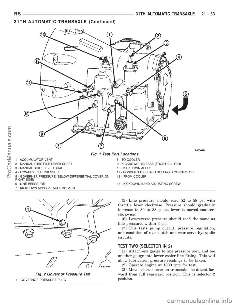
Fig. 1 Test Port Locations
1 - ACCUMULATOR VENT 8 - TO COOLER
2 - MANUAL THROTTLE LEVER SHAFT 9 - KICKDOWN RELEASE (FRONT CLUTCH)
3 - MANUAL SHIFT LEVER SHAFT 10 - KICKDOWN APPLY
4 - LOW-REVERSE PRESSURE 11 - CONVERTER CLUTCH SOLENOID CONNECTOR
5 - GOVERNER PRESSURE (BELOW DIFFERENTIAL COVER ON
RIGHT SIDE)12 - FROM COOLER
6 - LINE PRESSURE 13 - KICKDOWN BAND ADJUSTING SCREW
7 - KICKDOWN APPLY AT ACCUMULATOR
Fig. 2 Governor Pressure Tap
1 - GOVERNOR PRESSURE PLUG
RS31TH AUTOMATIC TRANSAXLE21-33
31TH AUTOMATIC TRANSAXLE (Continued)
ProCarManuals.com
Page 1591 of 2399
(4) Read pressures on both gauges as throttle lever
on transaxle is moved from full clockwise position to
full counterclockwise position.
(5) Line pressure should read 52 to 58 psi with
throttle lever clockwise. Pressure should gradually
increase to 80 to 88 psi. as lever is moved counter-
clockwise.
(6) Lubrication pressure should be 10 to 25 psi
with lever clockwise and 10 to 35 psi with lever at
full counterclockwise.
(7) This tests pump output, pressure regulation,
and condition of rear clutch and lubrication hydraulic
circuits.
TEST THREE (SELECTOR IN D)
(1) Attach gauges to line and kickdown release
ports.
(2) Operate engine at 1600 rpm for test.
(3) Move selector lever on transaxle two detents
forward from full rearward position. This is selector
D position.
(4) Read pressures on both gauges as throttle lever
on transaxle is moved from full clockwise to the full
counterclockwise position.
(5) Line pressure should read 52 to 58 psi with
throttle lever clockwise. Pressure should gradually
increase to 80 to 88 psi. as lever is moved counter-
clockwise.
(6) Kickdown release is pressurized only in direct
drive and should be same as line pressure within 3
psi, up to kickdown point.
(7) This tests pump output, pressure regulation,
and condition of rear clutch, front clutch, and
hydraulic circuits.
TEST FOUR (SELECTOR IN REVERSE)
(1) Attach 300 psi gauge (C-3292SP) to low-reverse
port.
(2) Operate engine at 1600 rpm for test.
(3) Move selector lever on transaxle four detents
forward from full rearward position. This is selector
R position.
(4) Low/reverse pressure should read 180 to 220
psi with throttle lever clockwise. Pressure should
gradually increase to 260 to 300 psi. as lever is
moved counterclockwise.(5) This tests pump output, pressure regulation,
and condition of front clutch and rear servo hydraulic
circuits.
(6) Move selector lever on transaxle to D position
to check that low/reverse pressure drops to zero.
(7) This tests for leakage into rear servo, due to
case porosity, which can cause reverse band burn out.
TEST RESULT INDICATIONS
(1) If proper line pressure, minimum to maximum,
is found in any one test, the pump and pressure reg-
ulator are working properly.
(2) Low pressure in D, 1, and 2 but correct pres-
sure in R, indicates rear clutch circuit leakage.
(3) Low pressure in D and R, but correct pressure
in 1 indicates front clutch circuit leakage.
(4) Low pressure in R and 1, but correct pressure
in 2 indicates rear servo circuit leakage.
(5) Low line pressure in all positions indicates a
defective pump, a clogged filter, or a stuck pressure
regulator valve.
GOVERNOR PRESSURE
Test only if transaxle shifts at wrong vehicle
speeds when throttle cable is correctly adjusted.
(1) Connect a 100 psi gauge to governor pressure
port. It is located at lower right side of case, below
differential cover (Fig. 2).
(2) Operate transaxle in third gear to read pres-
sures. The governor pressure should respond
smoothly to changes in mph and should return to 0
to 3 psi when vehicle is stopped. High pressure
(above 3 psi) at standstill will prevent the transaxle
from downshifting.
THROTTLE PRESSURE
No gauge port is provided for throttle pressure.
Incorrect throttle pressure should be suspected if
part throttle upshift speeds are either delayed or
occur too early in relation to vehicle speed. Engine
runaway on shifts can also be an indicator of low
throttle pressure setting, or misadjusted throttle
cable.
In no case should throttle pressure be adjusted
until the transaxle throttle cable adjustment has
been verified to be correct.
21 - 34 31TH AUTOMATIC TRANSAXLERS
31TH AUTOMATIC TRANSAXLE (Continued)
ProCarManuals.com
Page 1597 of 2399
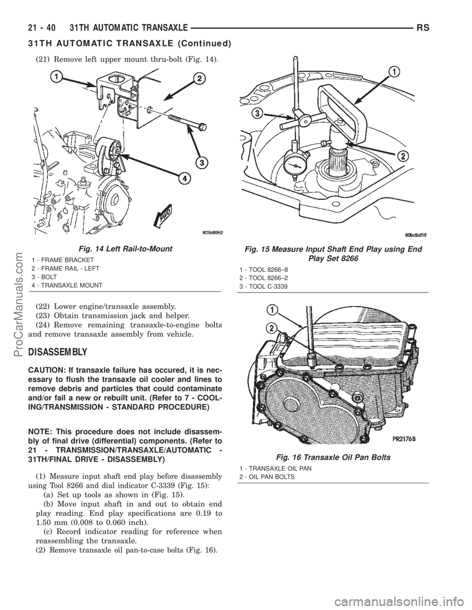
(21) Remove left upper mount thru-bolt (Fig. 14).
(22) Lower engine/transaxle assembly.
(23) Obtain transmission jack and helper.
(24) Remove remaining transaxle-to-engine bolts
and remove transaxle assembly from vehicle.
DISASSEMBLY
CAUTION: If transaxle failure has occured, it is nec-
essary to flush the transaxle oil cooler and lines to
remove debris and particles that could contaminate
and/or fail a new or rebuilt unit. (Refer to 7 - COOL-
ING/TRANSMISSION - STANDARD PROCEDURE)
NOTE: This procedure does not include disassem-
bly of final drive (differential) components. (Refer to
21 - TRANSMISSION/TRANSAXLE/AUTOMATIC -
31TH/FINAL DRIVE - DISASSEMBLY)
(1)
Measure input shaft end play before disassembly
using Tool 8266 and dial indicator C-3339 (Fig. 15):
(a) Set up tools as shown in (Fig. 15).
(b) Move input shaft in and out to obtain end
play reading. End play specifications are 0.19 to
1.50 mm (0.008 to 0.060 inch).
(c) Record indicator reading for reference when
reassembling the transaxle.
(2)
Remove transaxle oil pan-to-case bolts (Fig. 16).
Fig. 14 Left Rail-to-Mount
1 - FRAME BRACKET
2 - FRAME RAIL - LEFT
3 - BOLT
4 - TRANSAXLE MOUNT
Fig. 15 Measure Input Shaft End Play using End
Play Set 8266
1 - TOOL 8266±8
2 - TOOL 8266±2
3 - TOOL C-3339
Fig. 16 Transaxle Oil Pan Bolts
1 - TRANSAXLE OIL PAN
2 - OIL PAN BOLTS
21 - 40 31TH AUTOMATIC TRANSAXLERS
31TH AUTOMATIC TRANSAXLE (Continued)
ProCarManuals.com
Page 1604 of 2399
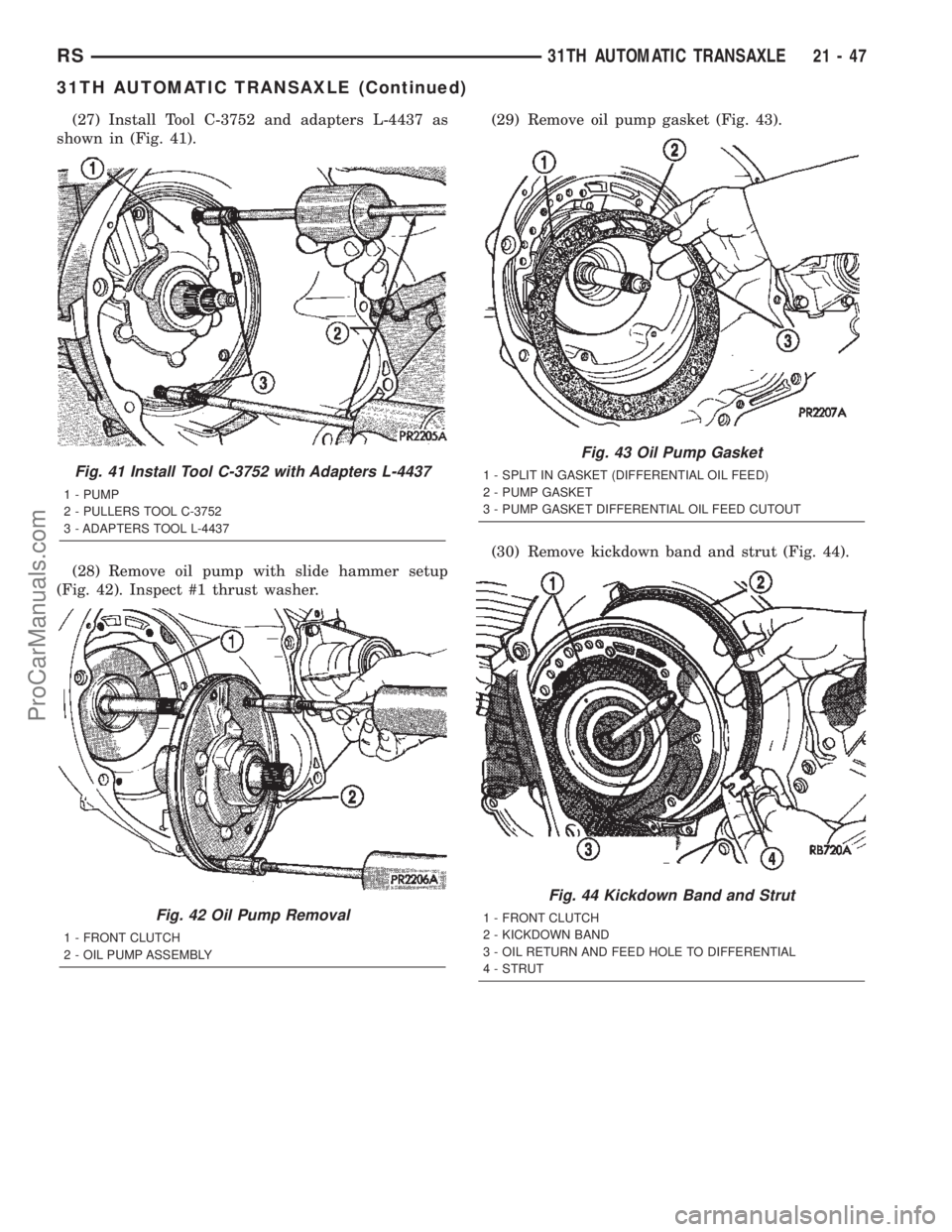
(27) Install Tool C-3752 and adapters L-4437 as
shown in (Fig. 41).
(28) Remove oil pump with slide hammer setup
(Fig. 42). Inspect #1 thrust washer.(29) Remove oil pump gasket (Fig. 43).
(30) Remove kickdown band and strut (Fig. 44).
Fig. 41 Install Tool C-3752 with Adapters L-4437
1 - PUMP
2 - PULLERS TOOL C-3752
3 - ADAPTERS TOOL L-4437
Fig. 42 Oil Pump Removal
1 - FRONT CLUTCH
2 - OIL PUMP ASSEMBLY
Fig. 43 Oil Pump Gasket
1 - SPLIT IN GASKET (DIFFERENTIAL OIL FEED)
2 - PUMP GASKET
3 - PUMP GASKET DIFFERENTIAL OIL FEED CUTOUT
Fig. 44 Kickdown Band and Strut
1 - FRONT CLUTCH
2 - KICKDOWN BAND
3 - OIL RETURN AND FEED HOLE TO DIFFERENTIAL
4 - STRUT
RS31TH AUTOMATIC TRANSAXLE21-47
31TH AUTOMATIC TRANSAXLE (Continued)
ProCarManuals.com
Page 1608 of 2399
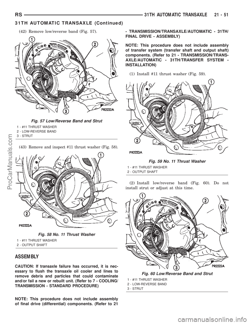
(42) Remove low/reverse band (Fig. 57).
(43)
Remove and inspect #11 thrust washer (Fig. 58).
ASSEMBLY
CAUTION: If transaxle failure has occurred, it is nec-
essary to flush the transaxle oil cooler and lines to
remove debris and particles that could contaminate
and/or fail a new or rebuilt unit. (Refer to 7 - COOLING/
TRANSMISSION - STANDARD PROCEDURE)
NOTE: This procedure does not include assembly
of final drive (differential) components. (Refer to 21- TRANSMISSION/TRANSAXLE/AUTOMATIC - 31TH/
FINAL DRIVE - ASSEMBLY)
NOTE: This procedure does not include assembly
of transfer system (transfer shaft and output shaft)
components. (Refer to 21 - TRANSMISSION/TRANS-
AXLE/AUTOMATIC - 31TH/TRANSFER SYSTEM -
INSTALLATION)
(1) Install #11 thrust washer (Fig. 59).
(2) Install low/reverse band (Fig. 60). Do not
install strut or adjust at this time.
Fig. 57 Low/Reverse Band and Strut
1 - #11 THRUST WASHER
2 - LOW-REVERSE BAND
3 - STRUT
Fig. 58 No. 11 Thrust Washer
1 - #11 THRUST WASHER
2 - OUTPUT SHAFT
Fig. 59 No. 11 Thrust Washer
1 - #11 THRUST WASHER
2 - OUTPUT SHAFT
Fig. 60 Low/Reverse Band and Strut
1 - #11 THRUST WASHER
2 - LOW-REVERSE BAND
3 - STRUT
RS31TH AUTOMATIC TRANSAXLE21-51
31TH AUTOMATIC TRANSAXLE (Continued)
ProCarManuals.com
Page 1611 of 2399
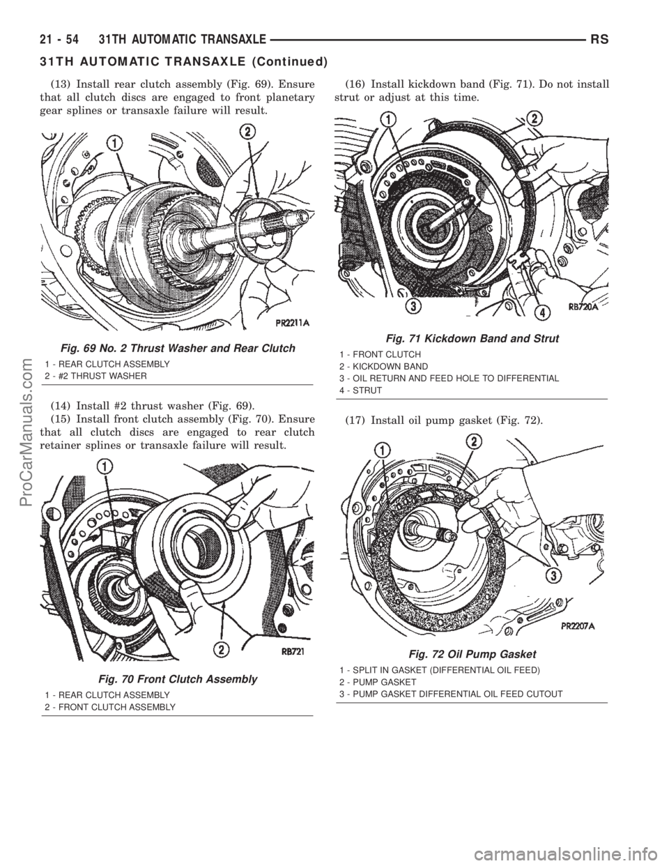
(13) Install rear clutch assembly (Fig. 69). Ensure
that all clutch discs are engaged to front planetary
gear splines or transaxle failure will result.
(14) Install #2 thrust washer (Fig. 69).
(15) Install front clutch assembly (Fig. 70). Ensure
that all clutch discs are engaged to rear clutch
retainer splines or transaxle failure will result.(16) Install kickdown band (Fig. 71). Do not install
strut or adjust at this time.
(17) Install oil pump gasket (Fig. 72).
Fig. 69 No. 2 Thrust Washer and Rear Clutch
1 - REAR CLUTCH ASSEMBLY
2 - #2 THRUST WASHER
Fig. 70 Front Clutch Assembly
1 - REAR CLUTCH ASSEMBLY
2 - FRONT CLUTCH ASSEMBLY
Fig. 71 Kickdown Band and Strut
1 - FRONT CLUTCH
2 - KICKDOWN BAND
3 - OIL RETURN AND FEED HOLE TO DIFFERENTIAL
4 - STRUT
Fig. 72 Oil Pump Gasket
1 - SPLIT IN GASKET (DIFFERENTIAL OIL FEED)
2 - PUMP GASKET
3 - PUMP GASKET DIFFERENTIAL OIL FEED CUTOUT
21 - 54 31TH AUTOMATIC TRANSAXLERS
31TH AUTOMATIC TRANSAXLE (Continued)
ProCarManuals.com
Page 1629 of 2399
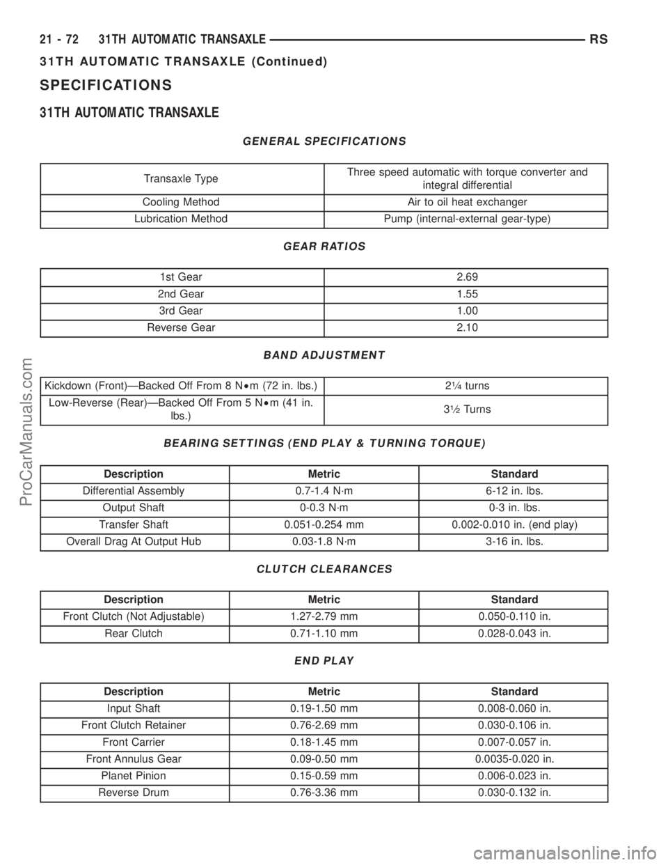
SPECIFICATIONS
31TH AUTOMATIC TRANSAXLE
GENERAL SPECIFICATIONS
Transaxle TypeThree speed automatic with torque converter and
integral differential
Cooling Method Air to oil heat exchanger
Lubrication Method Pump (internal-external gear-type)
GEAR RATIOS
1st Gear 2.69
2nd Gear 1.55
3rd Gear 1.00
Reverse Gear 2.10
BAND ADJUSTMENT
Kickdown (Front)ÐBacked Off From 8 N²m (72 in. lbs.) 21¤4turns
Low-Reverse (Rear)ÐBacked Off From 5 N²m (41 in.
lbs.)3
1¤2Turns
BEARING SETTINGS (END PLAY & TURNING TORQUE)
Description Metric Standard
Differential Assembly 0.7-1.4 N´m 6-12 in. lbs.
Output Shaft 0-0.3 N´m 0-3 in. lbs.
Transfer Shaft 0.051-0.254 mm 0.002-0.010 in. (end play)
Overall Drag At Output Hub 0.03-1.8 N´m 3-16 in. lbs.
CLUTCH CLEARANCES
Description Metric Standard
Front Clutch (Not Adjustable) 1.27-2.79 mm 0.050-0.110 in.
Rear Clutch 0.71-1.10 mm 0.028-0.043 in.
END PLAY
Description Metric Standard
Input Shaft 0.19-1.50 mm 0.008-0.060 in.
Front Clutch Retainer 0.76-2.69 mm 0.030-0.106 in.
Front Carrier 0.18-1.45 mm 0.007-0.057 in.
Front Annulus Gear 0.09-0.50 mm 0.0035-0.020 in.
Planet Pinion 0.15-0.59 mm 0.006-0.023 in.
Reverse Drum 0.76-3.36 mm 0.030-0.132 in.
21 - 72 31TH AUTOMATIC TRANSAXLERS
31TH AUTOMATIC TRANSAXLE (Continued)
ProCarManuals.com