2002 CHRYSLER CARAVAN battery
[x] Cancel search: batteryPage 1925 of 2399
(9) Torque crossover lever adjustment screw to 8
N´m (70 in. lbs.).No load should be applied to
the shifter lever in any direction (hands off)
while tightening screw.
(10) Verify gearshift lever travel through all gear
ranges with engine off (not running).
(11) Install center console assembly (Fig. 158).
Install and torque center console-to-gearshift mecha-
nism screws to 5 N´m (45 in. lbs.).
(12) Install cupholder plugs (Fig. 157).
(13) Install gearshift boot to console (Fig. 156).
Secure boot to console with three (3) retainer clips.
(14) Install gearshift knob to gearshift lever (Fig.
155). Orient shift pattern on knob
1¤4-turn clockwise,
push down and rotate1¤4-turn counter-clockwise and
release. Secure boot to knob.
(15) Connect battery negative cable.
GEARSHIFT CABLE -
SELECTOR
REMOVAL
(1) Disconnect battery negative cable.
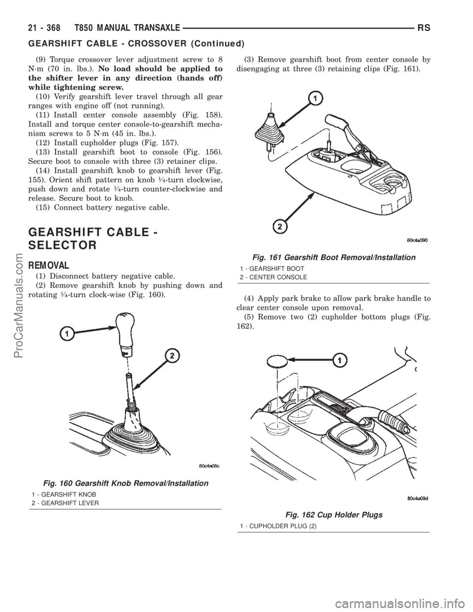
(2) Remove gearshift knob by pushing down and
rotating
1¤4-turn clock-wise (Fig. 160).(3) Remove gearshift boot from center console by
disengaging at three (3) retaining clips (Fig. 161).
(4) Apply park brake to allow park brake handle to
clear center console upon removal.
(5) Remove two (2) cupholder bottom plugs (Fig.
162).
Fig. 160 Gearshift Knob Removal/Installation
1 - GEARSHIFT KNOB
2 - GEARSHIFT LEVER
Fig. 161 Gearshift Boot Removal/Installation
1 - GEARSHIFT BOOT
2 - CENTER CONSOLE
Fig. 162 Cup Holder Plugs
1 - CUPHOLDER PLUG (2)
21 - 368 T850 MANUAL TRANSAXLERS
GEARSHIFT CABLE - CROSSOVER (Continued)
ProCarManuals.com
Page 1927 of 2399
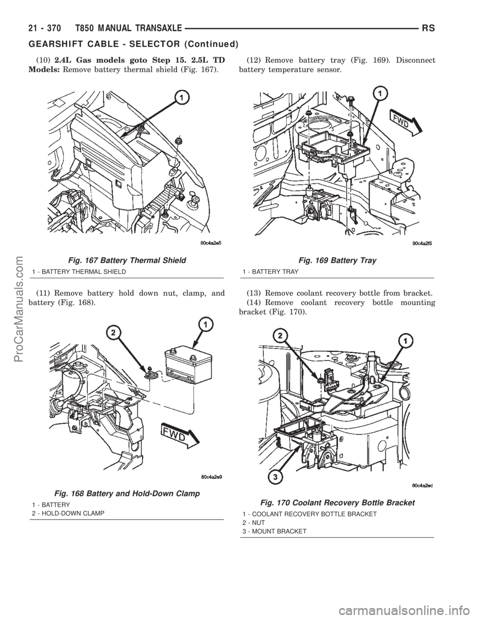
(10)2.4L Gas models goto Step 15. 2.5L TD
Models:Remove battery thermal shield (Fig. 167).
(11) Remove battery hold down nut, clamp, and
battery (Fig. 168).(12) Remove battery tray (Fig. 169). Disconnect
battery temperature sensor.
(13) Remove coolant recovery bottle from bracket.
(14) Remove coolant recovery bottle mounting
bracket (Fig. 170).
Fig. 167 Battery Thermal Shield
1 - BATTERY THERMAL SHIELD
Fig. 168 Battery and Hold-Down Clamp
1 - BATTERY
2 - HOLD-DOWN CLAMP
Fig. 169 Battery Tray
1 - BATTERY TRAY
Fig. 170 Coolant Recovery Bottle Bracket
1 - COOLANT RECOVERY BOTTLE BRACKET
2 - NUT
3 - MOUNT BRACKET
21 - 370 T850 MANUAL TRANSAXLERS
GEARSHIFT CABLE - SELECTOR (Continued)
ProCarManuals.com
Page 1929 of 2399
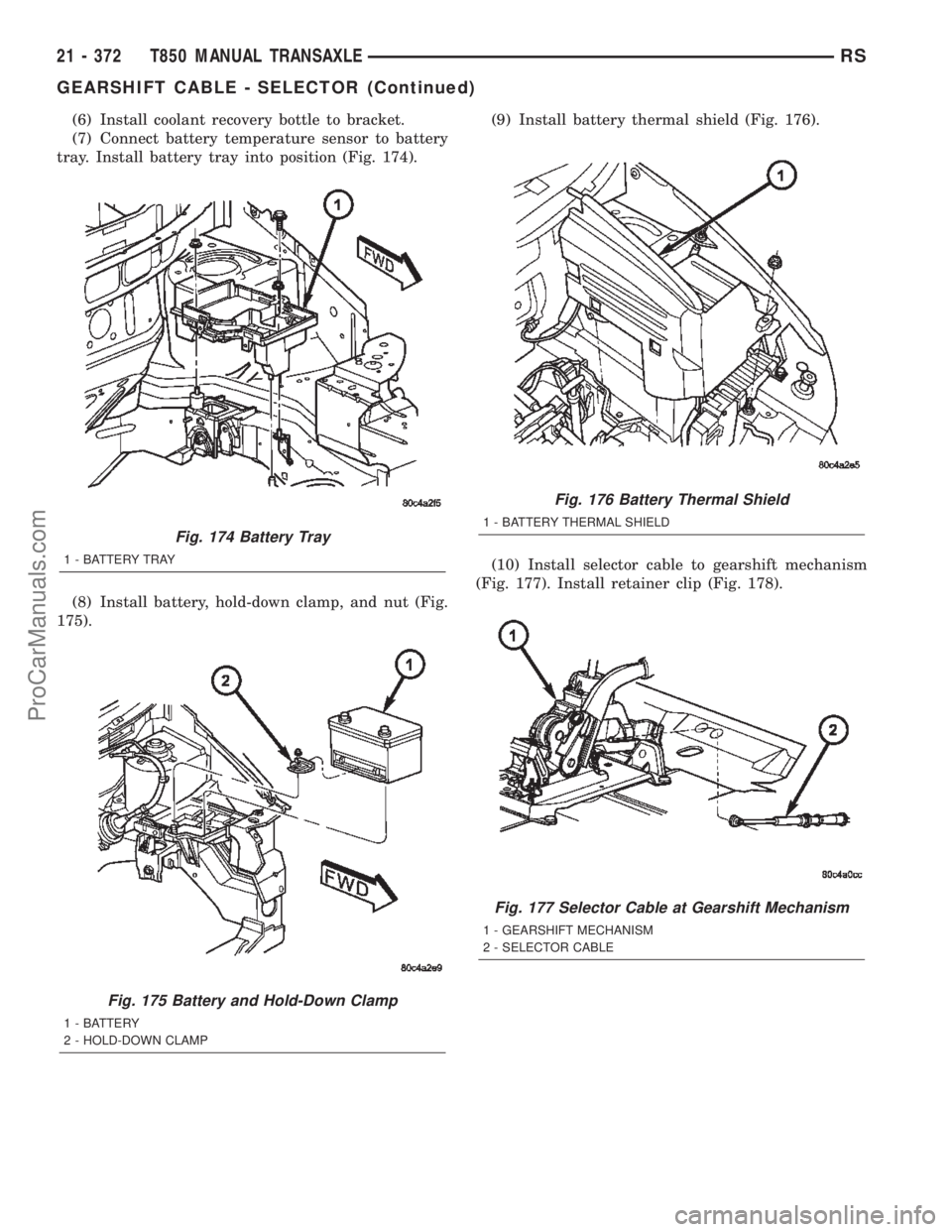
(6) Install coolant recovery bottle to bracket.
(7) Connect battery temperature sensor to battery
tray. Install battery tray into position (Fig. 174).
(8) Install battery, hold-down clamp, and nut (Fig.
175).(9) Install battery thermal shield (Fig. 176).
(10) Install selector cable to gearshift mechanism
(Fig. 177). Install retainer clip (Fig. 178).
Fig. 174 Battery Tray
1 - BATTERY TRAY
Fig. 175 Battery and Hold-Down Clamp
1 - BATTERY
2 - HOLD-DOWN CLAMP
Fig. 176 Battery Thermal Shield
1 - BATTERY THERMAL SHIELD
Fig. 177 Selector Cable at Gearshift Mechanism
1 - GEARSHIFT MECHANISM
2 - SELECTOR CABLE
21 - 372 T850 MANUAL TRANSAXLERS
GEARSHIFT CABLE - SELECTOR (Continued)
ProCarManuals.com
Page 1931 of 2399
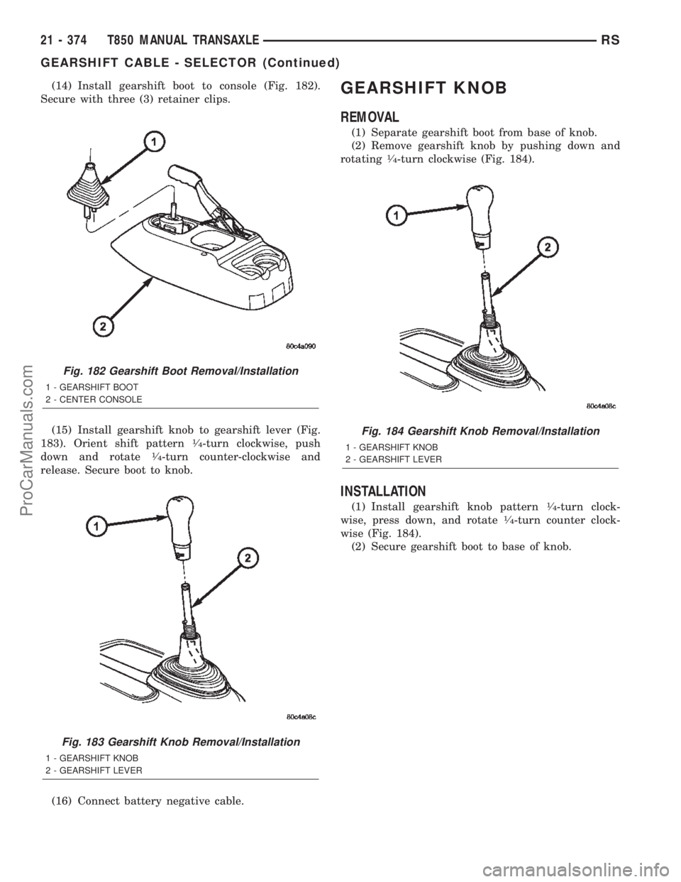
(14) Install gearshift boot to console (Fig. 182).
Secure with three (3) retainer clips.
(15) Install gearshift knob to gearshift lever (Fig.
183). Orient shift pattern
1¤4-turn clockwise, push
down and rotate1¤4-turn counter-clockwise and
release. Secure boot to knob.
(16) Connect battery negative cable.
GEARSHIFT KNOB
REMOVAL
(1) Separate gearshift boot from base of knob.
(2) Remove gearshift knob by pushing down and
rotating
1¤4-turn clockwise (Fig. 184).
INSTALLATION
(1) Install gearshift knob pattern1¤4-turn clock-
wise, press down, and rotate1¤4-turn counter clock-
wise (Fig. 184).
(2) Secure gearshift boot to base of knob.
Fig. 182 Gearshift Boot Removal/Installation
1 - GEARSHIFT BOOT
2 - CENTER CONSOLE
Fig. 183 Gearshift Knob Removal/Installation
1 - GEARSHIFT KNOB
2 - GEARSHIFT LEVER
Fig. 184 Gearshift Knob Removal/Installation
1 - GEARSHIFT KNOB
2 - GEARSHIFT LEVER
21 - 374 T850 MANUAL TRANSAXLERS
GEARSHIFT CABLE - SELECTOR (Continued)
ProCarManuals.com
Page 1932 of 2399
GEARSHIFT MECHANISM
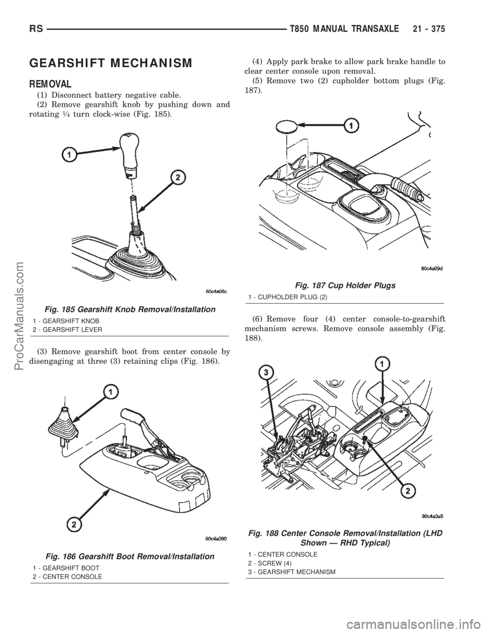
REMOVAL
(1) Disconnect battery negative cable.
(2) Remove gearshift knob by pushing down and
rotating
1¤4turn clock-wise (Fig. 185).
(3) Remove gearshift boot from center console by
disengaging at three (3) retaining clips (Fig. 186).(4) Apply park brake to allow park brake handle to
clear center console upon removal.
(5) Remove two (2) cupholder bottom plugs (Fig.
187).
(6) Remove four (4) center console-to-gearshift
mechanism screws. Remove console assembly (Fig.
188).
Fig. 185 Gearshift Knob Removal/Installation
1 - GEARSHIFT KNOB
2 - GEARSHIFT LEVER
Fig. 186 Gearshift Boot Removal/Installation
1 - GEARSHIFT BOOT
2 - CENTER CONSOLE
Fig. 187 Cup Holder Plugs
1 - CUPHOLDER PLUG (2)
Fig. 188 Center Console Removal/Installation (LHD
Shown Ð RHD Typical)
1 - CENTER CONSOLE
2 - SCREW (4)
3 - GEARSHIFT MECHANISM
RST850 MANUAL TRANSAXLE21 - 375
ProCarManuals.com
Page 1936 of 2399
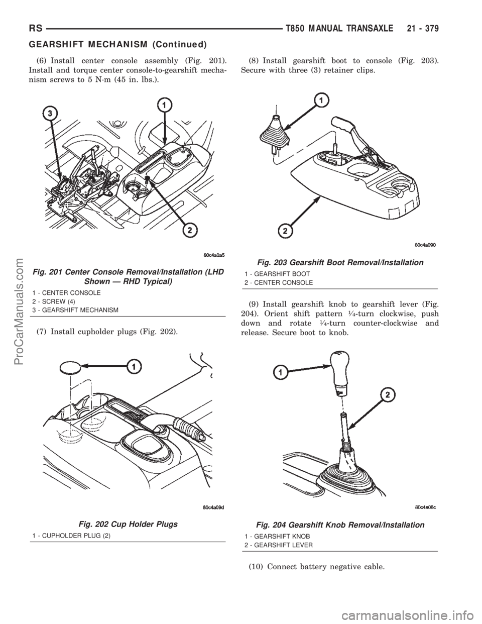
(6) Install center console assembly (Fig. 201).
Install and torque center console-to-gearshift mecha-
nism screws to 5 N´m (45 in. lbs.).
(7) Install cupholder plugs (Fig. 202).(8) Install gearshift boot to console (Fig. 203).
Secure with three (3) retainer clips.
(9) Install gearshift knob to gearshift lever (Fig.
204). Orient shift pattern
1¤4-turn clockwise, push
down and rotate1¤4-turn counter-clockwise and
release. Secure boot to knob.
(10) Connect battery negative cable.
Fig. 201 Center Console Removal/Installation (LHD
Shown Ð RHD Typical)
1 - CENTER CONSOLE
2 - SCREW (4)
3 - GEARSHIFT MECHANISM
Fig. 202 Cup Holder Plugs
1 - CUPHOLDER PLUG (2)
Fig. 203 Gearshift Boot Removal/Installation
1 - GEARSHIFT BOOT
2 - CENTER CONSOLE
Fig. 204 Gearshift Knob Removal/Installation
1 - GEARSHIFT KNOB
2 - GEARSHIFT LEVER
RST850 MANUAL TRANSAXLE21 - 379
GEARSHIFT MECHANISM (Continued)
ProCarManuals.com
Page 1971 of 2399
SENSOR - TPM
DESCRIPTION
On vehicles equipped with Tire Pressure Monitor-
ing, one tire pressure sensor is mounted to each
wheel (Fig. 19). Each sensor has an internal battery
that lasts up to 10 years. The battery is not service-
able. At the time of battery failure, the sensor must
be replaced. The serviceable components of the tire
pressure sensor are:
²Sensor-To-Wheel Grommet
²Valve Stem Cap
²Valve Stem Core
Valve stem caps and cores are specifically designed
for the tire pressure monitoring sensors. Although
similar to standard valve stem caps and cores, they
are different.
CAUTION: Do not use a standard valve stem cap or
core in a tire pressure sensor. Always use the orig-
inal equipment style sensor cap and core.
CAUTION: Do not reuse the Sensor-To Wheel Grom-
met. Always use a new grommet when installing a
pressure sensor and properly torque the sensor
nut.
CAUTION: Do not try to install a tire pressure sen-
sor in a steel wheel or aftermarket wheel. Use only
in original style factory wheels.
OPERATION
Tire pressure sensors are battery operated. They
transmit tire pressure data once every minute at
speeds above 20 mph (32 km/h) or up to once every
hour when stationary (parked). For additional infor-
mation, refer to Appropriate Diagnostic Information.
CAUTION
CAUTION: The use of tire sealants is strictly prohib-
ited for vehicles equipped with the Tire Pressure
Monitoring system. Tire sealants can clog tire pres-
sure sensors.
CAUTION: Tire pressure sensor valve stem caps
and cores are specially designed for the sensors.
Due to risk of corrosion, do not use a standard
valve stem cap or core in a tire pressure sensor in
place of the original equipment style sensor cap
and core.CAUTION: Do not attempt to install a tire pressure
sensor in a steel wheel or aftermarket wheel. Use
tire pressure sensors in original style factory
wheels only.
NOTE: TPM thresholds have been established for
the original tire size equipped on the vehicle. Use
original size tires only to maintain system accuracy.
DIAGNOSIS AND TESTING - TIRE PRESSURE
SENSOR
NOTE: Tire pressure may increase from 2 to 6 psi
(14 to 41 kPa) during normal driving conditions. Do
NOT reduce this normal pressure build up.
If a fault in the system is detected, always check
air pressure in the tires first with a known accurate
air gauge and correct the inflation pressure. If any
tire is low, inspectalltires.
If gauge-read pressure in the tires does not reflect
the reading on the EVIC, retrain the sensors, then
reevaluate (Refer to 22 - TIRES/WHEELS/TIRE
PRESSURE MONITORING/SENSOR - STANDARD
PROCEDURE). Refer to the appropriate diagnostic
information for complete diagnosis of the Tire Pres-
sure Monitoring System.
STANDARD PROCEDURE - TIRE PRESSURE
SENSOR RETRAIN
WARNING: DEATH OR SERIOUS INJURY CAN
OCCUR IF MAGNETICALLY SENSITIVE DEVICES
ARE EXPOSED TO THE RELEARN MAGNET. MAG-
NETS CAN AFFECT PACEMAKERS.
CAUTION: Never attempt to train more than one
vehicle at a time. System is capable of reading tire
pressure sensor transmissions from other near-by
vehicles.
Each time a wheel rotation or tire pressure sensor
replacement occurs the tire pressure sensors must be
retrained. This is necessary to inform the Electronic
Vehicle Information Center (EVIC) that a sensor
change was made and where. Retraining is accom-
plished through the EVIC used in conjunction with a
Re-learn Magnet, Special Tool 8821.
22 - 10 TIRES/WHEELSRS
ProCarManuals.com
Page 1984 of 2399
BODY
TABLE OF CONTENTS
page page
BODY
DESCRIPTION - VEHICLE IDENTIFICATION....1
WARNING
SAFETY PRECAUTIONS AND WARNINGS . . . 1
DIAGNOSIS AND TESTING
DIAGNOSIS AND TESTING - WATER LEAKS . 1
DIAGNOSIS AND TESTING - WIND NOISE . . . 2
STANDARD PROCEDURE
STANDARD PROCEDURE - PLASTIC BODY
PANEL REPAIR........................3
STANDARD PROCEDURE - HEAT STAKING . 10
SPECIFICATIONS
TORQUE............................11
BODY LUBRICATION...................12SPECIAL TOOLS
BODY..............................13
DOOR - FRONT.........................14
DOORS - SLIDING.......................24
DECKLID/HATCH/LIFTGATE/TAILGATE.......39
EXTERIOR.............................44
HOOD.................................60
INSTRUMENT PANEL.....................63
INTERIOR..............................72
PAINT.................................83
SEATS................................85
STATIONARY GLASS....................107
WEATHERSTRIP/SEALS..................112
BODY STRUCTURE.....................115
BODY
DESCRIPTION - VEHICLE IDENTIFICATION
Throughout this group, references to the
DaimlerChrysler Corporation vehicle family identifi-
cation code are used when describing a procedure
that is unique to that vehicle. Refer to Introduction
Group of this manual for detailed information on
vehicle identification. If a procedure is common to all
vehicles covered in this manual, no reference will be
made to a vehicle family code.
WARNING
SAFETY PRECAUTIONS AND WARNINGS
WARNING: USE A OSHA APPROVED BREATHING
FILTER WHEN SPRAYING PAINT OR SOLVENTS IN
A CONFINED AREA. PERSONAL INJURY CAN
RESULT.
AVOID PROLONGED SKIN CONTACT WITH PETRO-
LEUM OR ALCOHOL ± BASED CLEANING SOL-
VENTS. PERSONAL INJURY CAN RESULT.
DO NOT STAND UNDER A HOISTED VEHICLE THAT
IS NOT PROPERLY SUPPORTED ON SAFETY
STANDS. PERSONAL INJURY CAN RESULT.
CAUTION: When holes must be drilled or punched
in an inner body panel, verify depth of space to the
outer body panel, electrical wiring, or other compo-
nents. Damage to vehicle can result.
Do not weld exterior panels unless combustiblematerial on the interior of vehicle is removed from
the repair area. Fire or hazardous conditions, can
result.
Always have a fire extinguisher ready for use when
welding.
Disconnect the negative (-) cable clamp from the
battery when servicing electrical components that
are live when the ignition is OFF. Damage to electri-
cal system can result.
Do not use abrasive chemicals or compounds on
painted surfaces. Damage to finish can result.
Do not use harsh alkaline based cleaning solvents
on painted or upholstered surfaces. Damage to fin-
ish or color can result.
Do not hammer or pound on plastic trim panel
when servicing interior trim. Plastic panels can
break.
DIAGNOSIS AND TESTING
DIAGNOSIS AND TESTING - WATER LEAKS
Water leaks can be caused by poor sealing,
improper body component alignment, body seam
porosity, missing plugs, or blocked drain holes. Cen-
trifugal and gravitational force can cause water to
drip from a location away from the actual leak point,
making leak detection difficult. All body sealing
points should be water tight in normal wet-driving
conditions. Water flowing downward from the front of
the vehicle should not enter the passenger or luggage
compartment. Moving sealing surfaces will not
always seal water tight under all conditions. At
times, side glass or door seals will allow water to
RSBODY23-1
ProCarManuals.com