2002 CHRYSLER CARAVAN oil change
[x] Cancel search: oil changePage 1363 of 2399
INSTALLATION
INSTALLATION.......................47
INSTALLATION.......................48
OIL PRESSURE SENSOR/SWITCH
DESCRIPTION.........................48
REMOVAL.............................48
INSTALLATION.........................48
OIL TEMPERATURE SENSOR
DESCRIPTION.........................48
REMOVAL.............................48
INSTALLATION.........................48
OIL PRESSURE RELIEF VALVE
DESCRIPTION.........................49
REMOVAL.............................49
INSTALLATION.........................49
OIL COOLER & LINES
REMOVAL.............................50
INSTALLATION.........................50
OIL FILTER
DESCRIPTION.........................51
REMOVAL.............................51
INSTALLATION.........................51
OIL JET
DESCRIPTION.........................52
REMOVAL.............................52
INSTALLATION.........................52
INTAKE MANIFOLD
DESCRIPTION.........................52
REMOVAL.............................52INSTALLATION.........................52
VALVE TIMING
STANDARD PROCEDURE - LOCKING ENGINE
90É AFTER TDC.......................53
BALANCE SHAFT
DESCRIPTION.........................54
OPERATION...........................54
REMOVAL.............................55
INSTALLATION.........................55
TIMING BELT / CHAIN COVER(S)
REMOVAL
REMOVAL - TIMING BELT OUTER COVER . . 56
REMOVAL - TIMING BELT INNER COVER . . . 56
INSTALLATION
INSTALLATION - TIMING BELT OUTER
COVER.............................56
INSTALLATION - TIMING BELT INNER
COVER.............................57
TIMING BELT IDLER PULLEY
REMOVAL.............................58
INSTALLATION.........................58
TMNG BELT/CHAIN TENSIONER
REMOVAL.............................59
INSTALLATION.........................59
ADJUSTMENTS
ADJUSTMENT - TIMING BELT TENSIONER . 60
TIMING BELT/CHAIN AND SPROCKETS
REMOVAL.............................60
INSTALLATION.........................61
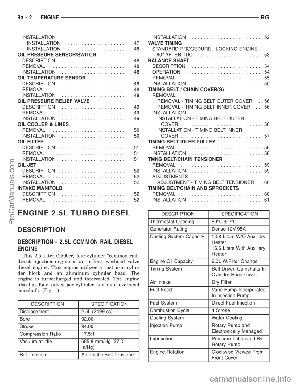
ENGINE 2.5L TURBO DIESEL
DESCRIPTION
DESCRIPTION - 2.5L COMMON RAIL DIESEL
ENGINE
This 2.5 Liter (2500cc) four-cylinder ªcommon railº
direct injection engine is an in-line overhead valve
diesel engine. This engine utilizes a cast iron cylin-
der block and an aluminum cylinder head. The
engine is turbocharged and intercooled. The engine
also has four valves per cylinder and dual overhead
camshafts (Fig. 1).
DESCRIPTION SPECIFICATION
Displacement 2.5L (2499 cc)
Bore 92.00
Stroke 94.00
Compression Ratio 17.5:1
Vacuum at Idle 685.8 mm/Hg (27.0
In/Hg)
Belt Tension Automatic Belt Tensioner
DESCRIPTION SPECIFICATION
Thermostat Opening 80ÉC 2ÉC
Generator Rating Denso 12V-95A
Cooling System Capacity 13.8 Liters W/O Auxiliary
Heater
16.6 Liters With Auxiliary
Heater
Engine Oil Capacity 6.0L W/Filter Change
Timing System Belt Driven Camshafts In
Cylinder Head Cover
Air Intake Dry Filter
Fuel Feed Vane Pump Incorporated
In Injection Pump
Fuel System Direct Fuel Injection
Combustion Cycle 4 Stroke
Cooling System Water Cooling
Injection Pump Rotary Pump and
Electronically Managed
Lubrication Pressure Lubricated By
Rotary Pump
Engine Rotation Clockwise Viewed From
Front Cover
9a - 2 ENGINERG
ProCarManuals.com
Page 1401 of 2399
assembly, determined by the numbers stamped on
the crown of individual pistons. Engine cylinders are
numbered starting from gear train end of the engine.
Face arrow on top of piston toward front of
engine. Therefore, the numbers stamped on connect-
ing rod big end should face toward the injection
pump side of engine. To insert piston into cylinder
use a ring compressor (VM.1065) as shown in (Fig.
57).
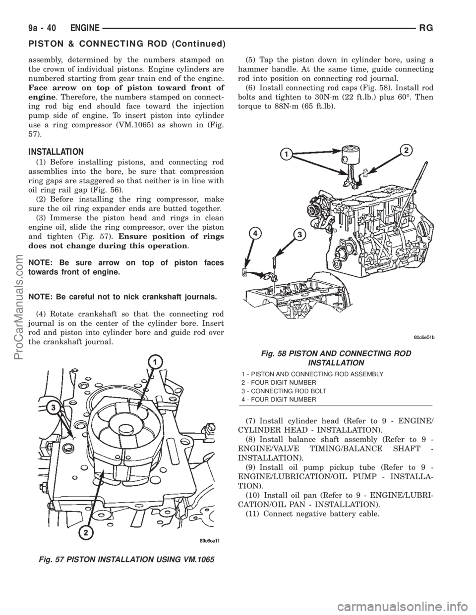
INSTALLATION
(1) Before installing pistons, and connecting rod
assemblies into the bore, be sure that compression
ring gaps are staggered so that neither is in line with
oil ring rail gap (Fig. 56).
(2) Before installing the ring compressor, make
sure the oil ring expander ends are butted together.
(3) Immerse the piston head and rings in clean
engine oil, slide the ring compressor, over the piston
and tighten (Fig. 57).Ensure position of rings
does not change during this operation.
NOTE: Be sure arrow on top of piston faces
towards front of engine.
NOTE: Be careful not to nick crankshaft journals.
(4) Rotate crankshaft so that the connecting rod
journal is on the center of the cylinder bore. Insert
rod and piston into cylinder bore and guide rod over
the crankshaft journal.(5) Tap the piston down in cylinder bore, using a
hammer handle. At the same time, guide connecting
rod into position on connecting rod journal.
(6) Install connecting rod caps (Fig. 58). Install rod
bolts and tighten to 30N´m (22 ft.lb.) plus 60É. Then
torque to 88N´m (65 ft.lb).
(7) Install cylinder head (Refer to 9 - ENGINE/
CYLINDER HEAD - INSTALLATION).
(8) Install balance shaft assembly (Refer to 9 -
ENGINE/VALVE TIMING/BALANCE SHAFT -
INSTALLATION).
(9) Install oil pump pickup tube (Refer to 9 -
ENGINE/LUBRICATION/OIL PUMP - INSTALLA-
TION).
(10) Install oil pan (Refer to 9 - ENGINE/LUBRI-
CATION/OIL PAN - INSTALLATION).
(11) Connect negative battery cable.
Fig. 57 PISTON INSTALLATION USING VM.1065
Fig. 58 PISTON AND CONNECTING ROD
INSTALLATION
1 - PISTON AND CONNECTING ROD ASSEMBLY
2 - FOUR DIGIT NUMBER
3 - CONNECTING ROD BOLT
4 - FOUR DIGIT NUMBER
9a - 40 ENGINERG
PISTON & CONNECTING ROD (Continued)
ProCarManuals.com
Page 1529 of 2399
GEAR
TABLE OF CONTENTS
page page
GEAR
DESCRIPTION.........................26
OPERATION...........................26
WARNING
WARNINGS AND CAUTIONS.............26
REMOVAL
REMOVAL - LHD GEAR.................26
REMOVAL - RHD GEAR................29INSTALLATION
INSTALLATION - LHD GEAR.............32
INSTALLATION - RHD GEAR.............33
SPECIAL TOOLS
POWER STEERING GEAR..............34
OUTER TIE ROD
REMOVAL.............................34
INSTALLATION.........................34
GEAR
DESCRIPTION
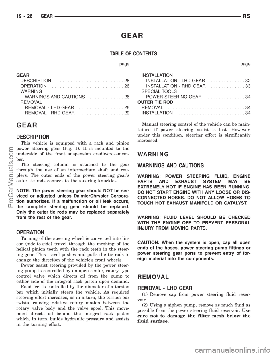
This vehicle is equipped with a rack and pinion
power steering gear (Fig. 1). It is mounted to the
underside of the front suspension cradle/crossmem-
ber.
The steering column is attached to the gear
through the use of an intermediate shaft and cou-
plers. The outer ends of the power steering gear's
outer tie rods connect to the steering knuckles.
NOTE: The power steering gear should NOT be ser-
viced or adjusted unless DaimlerChrysler Corpora-
tion authorizes. If a malfunction or oil leak occurs,
the complete steering gear should be replaced.
Only the outer tie rods may be replaced separately
from the rest of the gear.
OPERATION
Turning of the steering wheel is converted into lin-
ear (side-to-side) travel through the meshing of the
helical pinion teeth with the rack teeth in the steer-
ing gear. This travel pushes and pulls the tie rods to
change the direction of the vehicle's front wheels.
Power assist steering provided by the power steer-
ing pump is controlled by an open center, rotary type
control valve which directs oil from the pump to
either side of the integral rack piston upon demand.
Road feel is controlled by the diameter of a torsion
bar which initially steers the vehicle. As required
steering effort increases, as in a turn, the torsion bar
twists, causing relative rotary motion between the
rotary valve body and the valve spool. This move-
ment directs oil behind the integral rack piston
which, in turn, builds hydraulic pressure and assists
in the turning effort.Manual steering control of the vehicle can be main-
tained if power steering assist is lost. However,
under this condition, steering effort is significantly
increased.
WARNING
WARNINGS AND CAUTIONS
WARNING: POWER STEERING FLUID, ENGINE
PARTS AND EXHAUST SYSTEM MAY BE
EXTREMELY HOT IF ENGINE HAS BEEN RUNNING.
DO NOT START ENGINE WITH ANY LOOSE OR DIS-
CONNECTED HOSES. DO NOT ALLOW HOSES TO
TOUCH HOT EXHAUST MANIFOLD OR CATALYST.
WARNING: FLUID LEVEL SHOULD BE CHECKED
WITH THE ENGINE OFF TO PREVENT PERSONAL
INJURY FROM MOVING PARTS.
CAUTION: When the system is open, cap all open
ends of the hoses, power steering pump fittings or
power steering gear ports to prevent entry of for-
eign material into the components.
REMOVAL
REMOVAL - LHD GEAR
(1) Remove cap from power steering fluid reser-
voir.
(2) Using a siphon pump, remove as much fluid as
possible from the power steering fluid reservoir.Use
care not to damage the filter mesh below the
fluid surface.
19 - 26 GEARRS
ProCarManuals.com
Page 1558 of 2399
TRANSMISSION/TRANSAXLE
TABLE OF CONTENTS
page page
POWER TRANSFER UNIT..................1
31TH AUTOMATIC TRANSAXLE.............2141TE AUTOMATIC TRANSAXLE............161
T850 MANUAL TRANSAXLE...............308
POWER TRANSFER UNIT
TABLE OF CONTENTS
page page
POWER TRANSFER UNIT
DESCRIPTION..........................1
OPERATION............................3
DIAGNOSIS AND TESTING
SEAL IDENTIFICATION..................3
FLUID LEAK DIAGNOSIS................4
STANDARD PROCEDURE
STANDARD PROCEDURE - FLUID LEVEL
INSPECTION..........................5
STANDARD PROCEDURE - PTU FLUID
CHANGE.............................5
REMOVAL.............................6
INSTALLATION..........................7
ADJUSTMENTS
OUTPUT FLANGE SHIM SELECTION.......7
SPECIFICATIONS
TORQUE.............................8
SPECIAL TOOLS
SDP POWER TRANSFER UNIT............8
DIFFERENTIAL CARRIER SEAL
REMOVAL.............................9
INSTALLATION..........................9
END COVER BALL BEARING
REMOVAL.............................9INSTALLATION.........................10
END COVER SEAL
REMOVAL.............................11
INSTALLATION.........................11
HALF SHAFT INNER SEAL
REMOVAL.............................12
INSTALLATION.........................13
INPUT SHAFT COVER SEAL
REMOVAL.............................13
INSTALLATION.........................14
INPUT SHAFT END SEAL
REMOVAL.............................16
INSTALLATION.........................16
INPUT SHAFT SEAL
REMOVAL.............................17
INSTALLATION.........................18
OUTER HALF SHAFT SEAL
REMOVAL.............................19
INSTALLATION.........................19
REAR COVER O-RING
REMOVAL.............................19
INSTALLATION.........................20
POWER TRANSFER UNIT
DESCRIPTION
The Power Transfer Unit (P.T.U.) is attached to a
modified automatic transaxle case where the right
half shaft extension housing would normally be
located.
The Power Transfer Unit is sealed from the trans-
axle and has its own oil sump. The Unit uses MopartSAE 80W-90 Gear and Axle Lubricant (MS-9020) and
holds 1.15 liters (1.22 quarts).
Service of the Power Transfer Unit is limited to:
²Fluid Change
²Seals
²Gaskets
²One ball bearing
²Output flange
If the ring gear and pinion, any tapered roller
bearings, case, covers, or pinion carrier fail the entire
unit must be replaced.
RSTRANSMISSION/TRANSAXLE21-1
ProCarManuals.com
Page 1578 of 2399
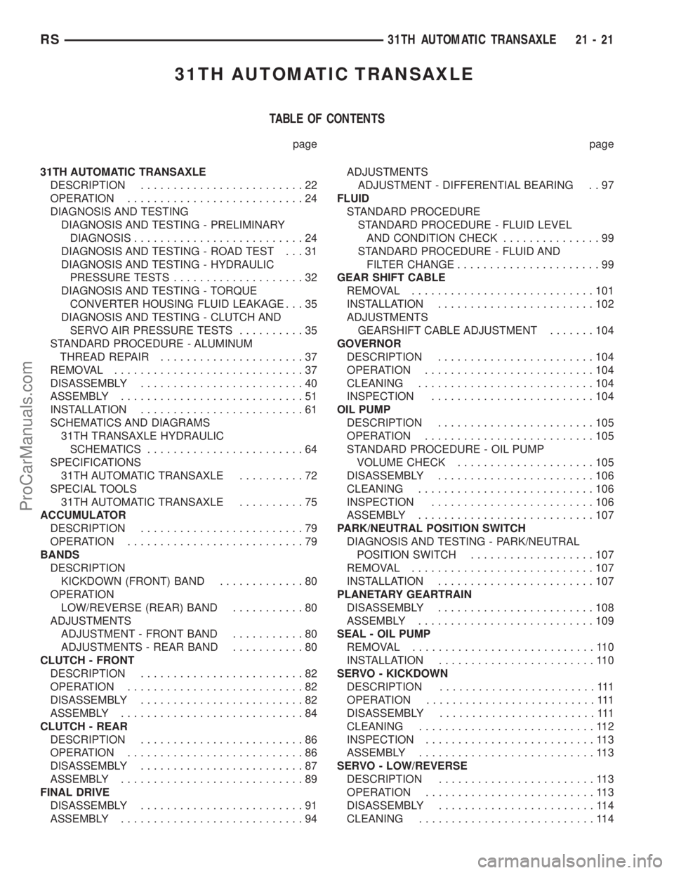
31TH AUTOMATIC TRANSAXLE
TABLE OF CONTENTS
page page
31TH AUTOMATIC TRANSAXLE
DESCRIPTION.........................22
OPERATION...........................24
DIAGNOSIS AND TESTING
DIAGNOSIS AND TESTING - PRELIMINARY
DIAGNOSIS..........................24
DIAGNOSIS AND TESTING - ROAD TEST . . . 31
DIAGNOSIS AND TESTING - HYDRAULIC
PRESSURE TESTS....................32
DIAGNOSIS AND TESTING - TORQUE
CONVERTER HOUSING FLUID LEAKAGE . . . 35
DIAGNOSIS AND TESTING - CLUTCH AND
SERVO AIR PRESSURE TESTS..........35
STANDARD PROCEDURE - ALUMINUM
THREAD REPAIR......................37
REMOVAL.............................37
DISASSEMBLY.........................40
ASSEMBLY............................51
INSTALLATION.........................61
SCHEMATICS AND DIAGRAMS
31TH TRANSAXLE HYDRAULIC
SCHEMATICS........................64
SPECIFICATIONS
31TH AUTOMATIC TRANSAXLE..........72
SPECIAL TOOLS
31TH AUTOMATIC TRANSAXLE..........75
ACCUMULATOR
DESCRIPTION.........................79
OPERATION...........................79
BANDS
DESCRIPTION
KICKDOWN (FRONT) BAND.............80
OPERATION
LOW/REVERSE (REAR) BAND...........80
ADJUSTMENTS
ADJUSTMENT - FRONT BAND...........80
ADJUSTMENTS - REAR BAND...........80
CLUTCH - FRONT
DESCRIPTION.........................82
OPERATION...........................82
DISASSEMBLY.........................82
ASSEMBLY............................84
CLUTCH - REAR
DESCRIPTION.........................86
OPERATION...........................86
DISASSEMBLY.........................87
ASSEMBLY............................89
FINAL DRIVE
DISASSEMBLY.........................91
ASSEMBLY............................94ADJUSTMENTS
ADJUSTMENT - DIFFERENTIAL BEARING . . 97
FLUID
STANDARD PROCEDURE
STANDARD PROCEDURE - FLUID LEVEL
AND CONDITION CHECK...............99
STANDARD PROCEDURE - FLUID AND
FILTER CHANGE......................99
GEAR SHIFT CABLE
REMOVAL............................101
INSTALLATION........................102
ADJUSTMENTS
GEARSHIFT CABLE ADJUSTMENT.......104
GOVERNOR
DESCRIPTION........................104
OPERATION..........................104
CLEANING...........................104
INSPECTION.........................104
OIL PUMP
DESCRIPTION........................105
OPERATION..........................105
STANDARD PROCEDURE - OIL PUMP
VOLUME CHECK.....................105
DISASSEMBLY........................106
CLEANING...........................106
INSPECTION.........................106
ASSEMBLY...........................107
PARK/NEUTRAL POSITION SWITCH
DIAGNOSIS AND TESTING - PARK/NEUTRAL
POSITION SWITCH...................107
REMOVAL............................107
INSTALLATION........................107
PLANETARY GEARTRAIN
DISASSEMBLY........................108
ASSEMBLY...........................109
SEAL - OIL PUMP
REMOVAL............................110
INSTALLATION........................110
SERVO - KICKDOWN
DESCRIPTION........................111
OPERATION..........................111
DISASSEMBLY........................111
CLEANING...........................112
INSPECTION..........................113
ASSEMBLY...........................113
SERVO - LOW/REVERSE
DESCRIPTION........................113
OPERATION..........................113
DISASSEMBLY........................114
CLEANING...........................114
RS31TH AUTOMATIC TRANSAXLE21-21
ProCarManuals.com
Page 1579 of 2399
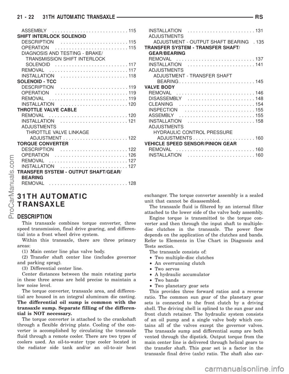
ASSEMBLY...........................115
SHIFT INTERLOCK SOLENOID
DESCRIPTION........................115
OPERATION..........................115
DIAGNOSIS AND TESTING - BRAKE/
TRANSMISSION SHIFT INTERLOCK
SOLENOID..........................117
REMOVAL............................117
INSTALLATION........................118
SOLENOID - TCC
DESCRIPTION........................119
OPERATION..........................119
REMOVAL............................119
INSTALLATION........................120
THROTTLE VALVE CABLE
REMOVAL............................120
INSTALLATION........................121
ADJUSTMENTS
THROTTLE VALVE LINKAGE
ADJUSTMENT.......................122
TORQUE CONVERTER
DESCRIPTION........................122
OPERATION..........................126
REMOVAL............................127
INSTALLATION........................127
TRANSFER SYSTEM - OUTPUT SHAFT/GEAR/
BEARING
REMOVAL............................128INSTALLATION........................131
ADJUSTMENTS
ADJUSTMENT - OUTPUT SHAFT BEARING . 135
TRANSFER SYSTEM - TRANSFER SHAFT/
GEAR/BEARING
REMOVAL............................137
INSTALLATION........................141
ADJUSTMENTS
ADJUSTMENT - TRANSFER SHAFT
BEARING...........................145
VALVE BODY
REMOVAL............................146
DISASSEMBLY........................148
CLEANING...........................154
INSPECTION.........................155
ASSEMBLY...........................155
INSTALLATION........................158
ADJUSTMENTS
HYDRAULIC CONTROL PRESSURE
ADJUSTMENTS......................160
VEHICLE SPEED SENSOR/PINION GEAR
REMOVAL............................160
INSTALLATION........................160
31TH AUTOMATIC
TRANSAXLE
DESCRIPTION
This transaxle combines torque converter, three
speed transmission, final drive gearing, and differen-
tial into a front wheel drive system.
Within this transaxle, there are three primary
areas:
(1) Main center line plus valve body.
(2) Transfer shaft center line (includes governor
and parking sprag).
(3) Differential center line.
Center distances between the main rotating parts
in these three areas are held precise to maintain a
low noise level.
The torque converter, transaxle area, and differen-
tial are housed in an integral aluminum die casting.
The differential oil sump is common with the
transaxle sump. Separate filling of the differen-
tial is NOT necessary.
The torque converter is attached to the crankshaft
through a flexible driving plate. Cooling of the con-
verter is accomplished by circulating the transaxle
fluid through a remote cooler. There are two types of
coolers used. An oil-to-water type cooler located in
the radiator side tank and/or an oil-to-air heatexchanger. The torque converter assembly is a sealed
unit that cannot be disassembled.
The transaxle fluid is filtered by an internal filter
attached to the lower side of the valve body assembly.
Engine torque is transmitted to the torque con-
verter and then through the input shaft to multiple-
disc clutches in the transaxle. The power flow
depends on the application of the clutches and bands.
Refer to Elements in Use Chart in Diagnosis and
Tests section.
The transaxle consists of:
²Two multiple-disc clutches
²An overrunning clutch
²Two servos
²A hydraulic accumulator
²Two bands
²Two planetary gear sets
This provides three forward ratios and a reverse
ratio. The common sun gear of the planetary gear
sets is connected to the front clutch by a driving
shell. The driving shell is splined to the sun gear and
front clutch retainer. The hydraulic system consists
of an oil pump and a single valve body which con-
tains all of the valves except the governor valves.
The transaxle sump and differential sump are both
vented through the dipstick. Output torque from the
main center line is delivered through helical gears to
the transfer shaft. This gear set is a factor in the
transaxle final drive (axle) ratio. The shaft also car-
21 - 22 31TH AUTOMATIC TRANSAXLERS
ProCarManuals.com
Page 1582 of 2399
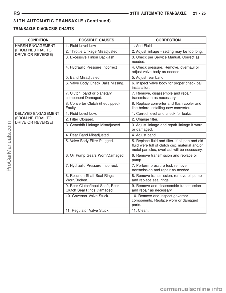
TRANSAXLE DIAGNOSIS CHARTS
CONDITION POSSIBLE CAUSES CORRECTION
HARSH ENGAGEMENT
(FROM NEUTRAL TO
DRIVE OR REVERSE)1. Fluid Level Low 1. Add Fluid
2. Throttle Linkage Misadjusted 2. Adjust linkage - setting may be too long.
3. Excessive Pinion Backlash 3. Check per Service Manual. Correct as
needed.
4. Hydraulic Pressure Incorrect 4. Check pressure. Remove, overhaul or
adjust valve body as needed.
5. Band Misadjusted. 5. Adjust rear band.
6. Valve Body Check Balls Missing. 6. Inspect valve body for proper check ball
installation.
7. Clutch, band or planetary
component Damaged.7. Remove, disassemble and repair
transmission as necessary.
8. Converter Clutch (if equipped)
Faulty.8. Replace converter and flush cooler and
line before installing new converter.
DELAYED ENGAGEMENT
(FROM NEUTRAL TO
DRIVE OR REVERSE)1. Fluid Level Low. 1. Correct level and check for leaks.
2. Filter Clogged. 2. Change filter.
3. Gearshift Linkage Misadjusted. 3. Adjust linkage and repair linkage if worn
or damaged.
4. Rear Band Misadjusted. 4. Adjust band.
5. Valve Body Filter Plugged. 5. Replace fluid and filter. If oil pan and old
fluid were full of clutch disc material and/or
metal particles, overhaul will be necessary.
6. Oil Pump Gears Worn/Damaged. 6. Remove transmission and replace oil
pump.
7. Hydraulic Pressure Incorrect. 7. Perform pressure test, remove
transmission and repair as needed.
8. Reaction Shaft Seal Rings
Worn/Broken.8. Remove transmission, remove oil pump
and replace seal rings.
9. Rear Clutch/Input Shaft, Rear
Clutch Seal Rings Damaged.9. Remove and disassemble transmission
and repair as necessary.
10. Governor Valve Stuck. 10. Remove and inspect governor
components. Replace worn or damaged
parts.
11. Regulator Valve Stuck. 11. Clean.
RS31TH AUTOMATIC TRANSAXLE21-25
31TH AUTOMATIC TRANSAXLE (Continued)
ProCarManuals.com
Page 1629 of 2399
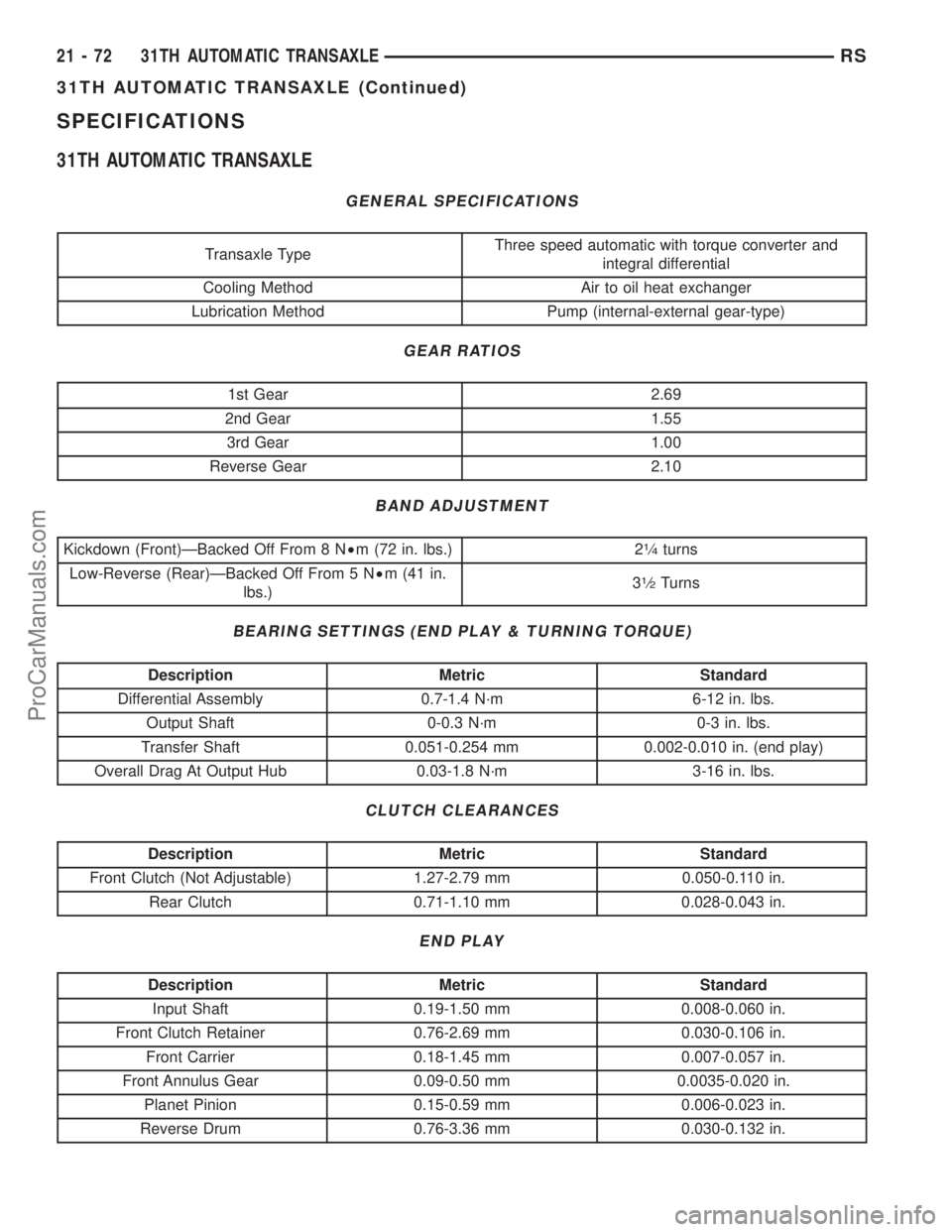
SPECIFICATIONS
31TH AUTOMATIC TRANSAXLE
GENERAL SPECIFICATIONS
Transaxle TypeThree speed automatic with torque converter and
integral differential
Cooling Method Air to oil heat exchanger
Lubrication Method Pump (internal-external gear-type)
GEAR RATIOS
1st Gear 2.69
2nd Gear 1.55
3rd Gear 1.00
Reverse Gear 2.10
BAND ADJUSTMENT
Kickdown (Front)ÐBacked Off From 8 N²m (72 in. lbs.) 21¤4turns
Low-Reverse (Rear)ÐBacked Off From 5 N²m (41 in.
lbs.)3
1¤2Turns
BEARING SETTINGS (END PLAY & TURNING TORQUE)
Description Metric Standard
Differential Assembly 0.7-1.4 N´m 6-12 in. lbs.
Output Shaft 0-0.3 N´m 0-3 in. lbs.
Transfer Shaft 0.051-0.254 mm 0.002-0.010 in. (end play)
Overall Drag At Output Hub 0.03-1.8 N´m 3-16 in. lbs.
CLUTCH CLEARANCES
Description Metric Standard
Front Clutch (Not Adjustable) 1.27-2.79 mm 0.050-0.110 in.
Rear Clutch 0.71-1.10 mm 0.028-0.043 in.
END PLAY
Description Metric Standard
Input Shaft 0.19-1.50 mm 0.008-0.060 in.
Front Clutch Retainer 0.76-2.69 mm 0.030-0.106 in.
Front Carrier 0.18-1.45 mm 0.007-0.057 in.
Front Annulus Gear 0.09-0.50 mm 0.0035-0.020 in.
Planet Pinion 0.15-0.59 mm 0.006-0.023 in.
Reverse Drum 0.76-3.36 mm 0.030-0.132 in.
21 - 72 31TH AUTOMATIC TRANSAXLERS
31TH AUTOMATIC TRANSAXLE (Continued)
ProCarManuals.com