2002 CHRYSLER CARAVAN change time
[x] Cancel search: change timePage 1656 of 2399
FLUID
STANDARD PROCEDURE
STANDARD PROCEDURE - FLUID LEVEL AND
CONDITION CHECK
NOTE: The transmission and differential sump have
a common oil sump with a communicating opening
between the two.
FLUID LEVEL CHECK
The torque converter fills in both the P Park and N
Neutral positions. Place the selector lever in P Park
to be sure that the fluid level check is accurate.The
engine should be running at idle speed for at
least one minute, with the vehicle on level
ground. This will assure complete oil level sta-
bilization between differential and transmis-
sion.The fluid should be at normal operating
temperature (approximately 82 C. or 180 F.). The
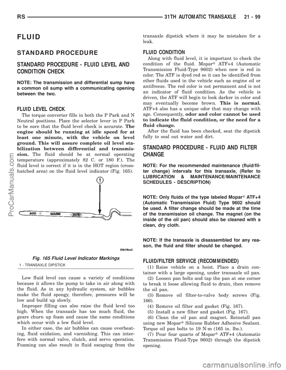
fluid level is correct if it is in the HOT region (cross-
hatched area) on the fluid level indicator (Fig. 165).
Low fluid level can cause a variety of conditions
because it allows the pump to take in air along with
the fluid. As in any hydraulic system, air bubbles
make the fluid spongy, therefore, pressures will be
low and build up slowly.
Improper filling can also raise the fluid level too
high. When the transaxle has too much fluid, the
gears churn up foam and cause the same conditions
which occur with a low fluid level.
In either case, the air bubbles can cause overheat-
ing, fluid oxidation, and varnishing. This can inter-
fere with normal valve, clutch, and servo operation.
Foaming can also result in fluid escaping from thetransaxle dipstick where it may be mistaken for a
leak.
FLUID CONDITION
Along with fluid level, it is important to check the
condition of the fluid. MopartATF+4 (Automatic
Transmission Fluid-Type 9602) when new is red in
color. The ATF is dyed red so it can be identified from
other fluids used in the vehicle such as engine oil or
antifreeze. The red color is not permanent and is not
an indicator of fluid condition. As the vehicle is
driven, the ATF will begin to look darker in color and
may eventually become brown.This is normal.
ATF+4 also has a unique odor that may change with
age. Consequently,odor and color cannot be used
to indicate the fluid condition, or the need for a
fluid change.
After the fluid has been checked, seat the dipstick
fully to seal out water and dirt.
STANDARD PROCEDURE - FLUID AND FILTER
CHANGE
NOTE: For the recommended maintenance (fluid/fil-
ter change) intervals for this transaxle, (Refer to
LUBRICATION & MAINTENANCE/MAINTENANCE
SCHEDULES - DESCRIPTION)
NOTE: Only fluids of the type labeled MoparTATF+4
(Automatic Transmission Fluid) Type 9602 should
be used. A filter change should be made at the time
of the transmission oil change. The magnet (on the
inside of the oil pan) should also be cleaned with a
clean, dry cloth.
NOTE: If the transaxle is disassembled for any rea-
son, the fluid and filter should be changed.
FLUID/FILTER SERVICE (RECOMMENDED)
(1) Raise vehicle on a hoist. Place a drain con-
tainer with a large opening, under transaxle oil pan.
(2) Loosen pan bolts and tap the pan at one corner
to break it loose allowing fluid to drain, then remove
the oil pan.
(3) Remove oil filter-to-valve body screws (Fig.
166).
(4) Remove oil filter and gasket (Fig. 167).
(5) Install a new filter and gasket (Fig. 167).
(6) Clean the oil pan and magnet. Reinstall pan
using new MopartSilicone Rubber Adhesive Sealant.
Torque oil pan bolts to 19 N´m (165 in. lbs.).
(7) Pour four quarts of MopartATF+4 (Automatic
Transmission Fluid-Type 9602) through the dipstick
opening.
Fig. 165 Fluid Level Indicator Markings
1 - TRANSAXLE DIPSTICK
RS31TH AUTOMATIC TRANSAXLE21-99
ProCarManuals.com
Page 1807 of 2399
(6) Adjust transmission fluid level shown on the
indicator according to the chart.
(7) Check transmission for leaks.
Low fluid level can cause a variety of conditions
because it allows the pump to take in air along with
the fluid. As in any hydraulic system, air bubbles
make the fluid spongy, therefore, pressures will be
low and build up slowly.
Improper filling can also raise the fluid level too
high. When the transaxle has too much fluid, the
gears churn up foam and cause the same conditions
which occur with a low fluid level.
In either case, air bubbles can cause overheating
and/or fluid oxidation, and varnishing. This can
interfere with normal valve, clutch, and accumulator
operation. Foaming can also result in fluid escaping
from the transaxle vent where it may be mistaken
for a leak.
FLUID CONDITION
Along with fluid level, it is important to check the
condition of the fluid. When the fluid smells burned,
and is contaminated with metal or friction material
particles, a complete transaxle recondition is proba-
bly required. Be sure to examine the fluid on the dip-
stick closely. If there is any doubt about its condition,
drain out a sample for a double check.
MopartATF+4 (Automatic Transmission Fluid-
Type 9602) when new is red in color. The ATF is dyed
red so it can be identified from other fluids used in
the vehicle such as engine oil or antifreeze. The red
color is not permanent and is not an indicator of fluid
condition. As the vehicle is driven, the ATF will begin
to look darker in color and may eventually become
brown.This is normal.ATF+4 also has a unique
odor that may change with age. Consequently,odor
and color cannot be used to indicate the fluid
condition or the need for a fluid change.
After the fluid has been checked, seat the dipstick
fully to seal out water and dirt.
STANDARD PROCEDURE - FLUID AND FILTER
SERVICE
NOTE: Refer to the maintenance schedules in
LUBRICATION and MAINTENANCE, or the vehicle
owner's manual, for the recommended maintenance
(fluid/filter change) intervals for this transaxle.
NOTE: Only fluids of the type labeled MoparTATF+4
(Automatic Transmission Fluid) Type 9602 should
be used. A filter change should be made at the time
of the transmission oil change. The magnet (on the
inside of the oil pan) should also be cleaned with a
clean, dry cloth.NOTE: If the transaxle is disassembled for any rea-
son, the fluid and filter should be changed.
FLUID/FILTER SERVICE (RECOMMENDED)
(1) Raise vehicle on a hoist. Refer to LUBRICA-
TION and MAINTENANCE for proper procedures.
Place a drain container with a large opening, under
transaxle oil pan.
(2) Loosen pan bolts and tap the pan at one corner
to break it loose allowing fluid to drain, then remove
the oil pan.
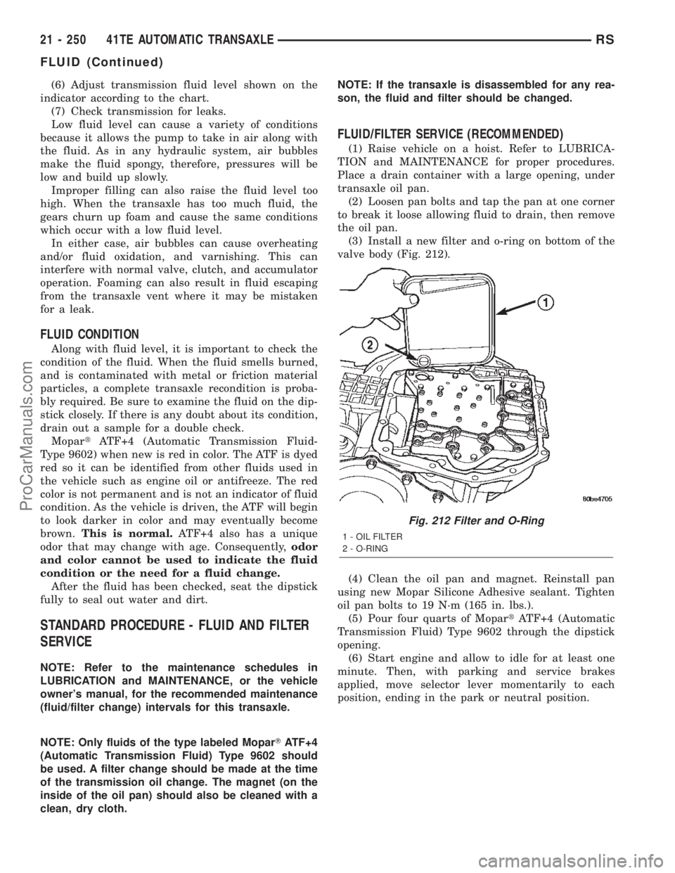
(3) Install a new filter and o-ring on bottom of the
valve body (Fig. 212).
(4) Clean the oil pan and magnet. Reinstall pan
using new Mopar Silicone Adhesive sealant. Tighten
oil pan bolts to 19 N´m (165 in. lbs.).
(5) Pour four quarts of MopartATF+4 (Automatic
Transmission Fluid) Type 9602 through the dipstick
opening.
(6) Start engine and allow to idle for at least one
minute. Then, with parking and service brakes
applied, move selector lever momentarily to each
position, ending in the park or neutral position.
Fig. 212 Filter and O-Ring
1 - OIL FILTER
2 - O-RING
21 - 250 41TE AUTOMATIC TRANSAXLERS
FLUID (Continued)
ProCarManuals.com
Page 1971 of 2399
SENSOR - TPM
DESCRIPTION
On vehicles equipped with Tire Pressure Monitor-
ing, one tire pressure sensor is mounted to each
wheel (Fig. 19). Each sensor has an internal battery
that lasts up to 10 years. The battery is not service-
able. At the time of battery failure, the sensor must
be replaced. The serviceable components of the tire
pressure sensor are:
²Sensor-To-Wheel Grommet
²Valve Stem Cap
²Valve Stem Core
Valve stem caps and cores are specifically designed
for the tire pressure monitoring sensors. Although
similar to standard valve stem caps and cores, they
are different.
CAUTION: Do not use a standard valve stem cap or
core in a tire pressure sensor. Always use the orig-
inal equipment style sensor cap and core.
CAUTION: Do not reuse the Sensor-To Wheel Grom-
met. Always use a new grommet when installing a
pressure sensor and properly torque the sensor
nut.
CAUTION: Do not try to install a tire pressure sen-
sor in a steel wheel or aftermarket wheel. Use only
in original style factory wheels.
OPERATION
Tire pressure sensors are battery operated. They
transmit tire pressure data once every minute at
speeds above 20 mph (32 km/h) or up to once every
hour when stationary (parked). For additional infor-
mation, refer to Appropriate Diagnostic Information.
CAUTION
CAUTION: The use of tire sealants is strictly prohib-
ited for vehicles equipped with the Tire Pressure
Monitoring system. Tire sealants can clog tire pres-
sure sensors.
CAUTION: Tire pressure sensor valve stem caps
and cores are specially designed for the sensors.
Due to risk of corrosion, do not use a standard
valve stem cap or core in a tire pressure sensor in
place of the original equipment style sensor cap
and core.CAUTION: Do not attempt to install a tire pressure
sensor in a steel wheel or aftermarket wheel. Use
tire pressure sensors in original style factory
wheels only.
NOTE: TPM thresholds have been established for
the original tire size equipped on the vehicle. Use
original size tires only to maintain system accuracy.
DIAGNOSIS AND TESTING - TIRE PRESSURE
SENSOR
NOTE: Tire pressure may increase from 2 to 6 psi
(14 to 41 kPa) during normal driving conditions. Do
NOT reduce this normal pressure build up.
If a fault in the system is detected, always check
air pressure in the tires first with a known accurate
air gauge and correct the inflation pressure. If any
tire is low, inspectalltires.
If gauge-read pressure in the tires does not reflect
the reading on the EVIC, retrain the sensors, then
reevaluate (Refer to 22 - TIRES/WHEELS/TIRE
PRESSURE MONITORING/SENSOR - STANDARD
PROCEDURE). Refer to the appropriate diagnostic
information for complete diagnosis of the Tire Pres-
sure Monitoring System.
STANDARD PROCEDURE - TIRE PRESSURE
SENSOR RETRAIN
WARNING: DEATH OR SERIOUS INJURY CAN
OCCUR IF MAGNETICALLY SENSITIVE DEVICES
ARE EXPOSED TO THE RELEARN MAGNET. MAG-
NETS CAN AFFECT PACEMAKERS.
CAUTION: Never attempt to train more than one
vehicle at a time. System is capable of reading tire
pressure sensor transmissions from other near-by
vehicles.
Each time a wheel rotation or tire pressure sensor
replacement occurs the tire pressure sensors must be
retrained. This is necessary to inform the Electronic
Vehicle Information Center (EVIC) that a sensor
change was made and where. Retraining is accom-
plished through the EVIC used in conjunction with a
Re-learn Magnet, Special Tool 8821.
22 - 10 TIRES/WHEELSRS
ProCarManuals.com
Page 1972 of 2399
NOTE: Use the following procedure to retrain all
four (4) road wheel tire pressure sensors. No
attempt should be made to retrain individual sen-
sors.
(1) Retrieve Re-learn Magnet, Special Tool 8821.
(2) Press MENU Button on EVIC until9RETRAIN
TIRE SENSORS - NO9is displayed.
(3) Press STEP button to select9YES9.
NOTE: There is a 60 second timer for training the
first sensor and a 30 second timer between training
the remaining sensors. If either of these timers
expire, the EVIC will abort the training procedure.
NOTE: If at any time the EVIC display reads(TRAIN-
ING ABORTED(, move the vehicle ahead at least
one foot and repeat the entire retraining procedure.
(4) Press MENU button to start retraining. Dis-
play will read9TRAIN LEFT FRONT TIRE9
NOTE: The order for retraining all five sensors is:
²Left Front
²Right Front
²Right Rear
²Left Rear
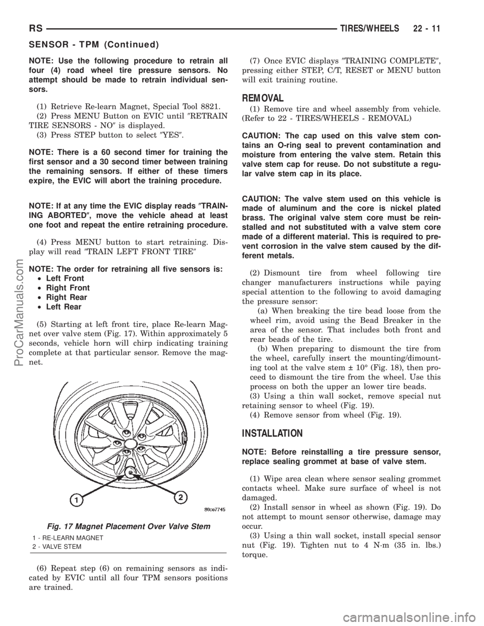
(5) Starting at left front tire, place Re-learn Mag-
net over valve stem (Fig. 17). Within approximately 5
seconds, vehicle horn will chirp indicating training
complete at that particular sensor. Remove the mag-
net.
(6) Repeat step (6) on remaining sensors as indi-
cated by EVIC until all four TPM sensors positions
are trained.(7) Once EVIC displays9TRAINING COMPLETE9,
pressing either STEP, C/T, RESET or MENU button
will exit training routine.
REMOVAL
(1) Remove tire and wheel assembly from vehicle.
(Refer to 22 - TIRES/WHEELS - REMOVAL)
CAUTION: The cap used on this valve stem con-
tains an O-ring seal to prevent contamination and
moisture from entering the valve stem. Retain this
valve stem cap for reuse. Do not substitute a regu-
lar valve stem cap in its place.
CAUTION: The valve stem used on this vehicle is
made of aluminum and the core is nickel plated
brass. The original valve stem core must be rein-
stalled and not substituted with a valve stem core
made of a different material. This is required to pre-
vent corrosion in the valve stem caused by the dif-
ferent metals.
(2) Dismount tire from wheel following tire
changer manufacturers instructions while paying
special attention to the following to avoid damaging
the pressure sensor:
(a) When breaking the tire bead loose from the
wheel rim, avoid using the Bead Breaker in the
area of the sensor. That includes both front and
rear beads of the tire.
(b) When preparing to dismount the tire from
the wheel, carefully insert the mounting/dimount-
ing tool at the valve stem 10É (Fig. 18), then pro-
ceed to dismount the tire from the wheel. Use this
process on both the upper an lower tire beads.
(3) Using a thin wall socket, remove special nut
retaining sensor to wheel (Fig. 19).
(4) Remove sensor from wheel (Fig. 19).
INSTALLATION
NOTE: Before reinstalling a tire pressure sensor,
replace sealing grommet at base of valve stem.
(1) Wipe area clean where sensor sealing grommet
contacts wheel. Make sure surface of wheel is not
damaged.
(2) Install sensor in wheel as shown (Fig. 19). Do
not attempt to mount sensor otherwise, damage may
occur.
(3) Using a thin wall socket, install special sensor
nut (Fig. 19). Tighten nut to 4 N´m (35 in. lbs.)
torque.
Fig. 17 Magnet Placement Over Valve Stem
1 - RE-LEARN MAGNET
2 - VALVE STEM
RSTIRES/WHEELS22-11
SENSOR - TPM (Continued)
ProCarManuals.com
Page 2247 of 2399
REAR CONTROL PANEL
With the rear control active, temperature selection
dictates indirectly the mode (floor or overhead air) of
the rear unit: a low temperature setting directs flow
to the overhead outlets and a high temperature set-
ting to the floor.
OPERATION - THREE ZONE ATC
Comfort temperature or perceived temperature is
affected by air flow, sun impinging on exposed skin,
etc. The air temperature may be higher or lower than
the comfort temperature. Three infrared sensors, two
in the instrument panel center stack, and one in the
overhead-mounted rear control panel, independently
measure the temperature of the driver, front passen-
ger, and rear compartment occupants to determine
their comfort level relative to the selected comfort
temperature. The HVAC computer in the control
module adjusts the air flow rate and temperature to
maintain the customer-perceived comfort tempera-
ture. The air temperature in the passenger compart-
ment at any time may be slightly higher or lower
than the comfort temperature. For instance, on
sunny summer days the air flow will probably be
cooler than the comfort temperature; on cold or
cloudy days and at night it will probably be slightly
warmer. Infrared Three-Zone Temperature Control
provides side-to-side and front-to-rear variation in
comfort temperature settings. The Infrared Three-
Zone Automatic Temperature Control fan provides a
continuously variable air flow rate to meet occupant
comfort requirements.
FRONT CONTROL PANEL
²AUTO HI/LO± This system features two sets of
automatic control logic that allow either a rapid cool-
down rate or a somewhat slower cool-down rate with
less fan noise. HI-AUTO controls the system to reach
its assigned temperature quickly with a higher fan
speed. LO-AUTO controls the system to reach its
assigned temperature somewhat slower with less fan
noise. Both modes will automatically engage auto
recirculation.
²DE-FROST± The front de-frost function is
active when the rear window defogger function is
active or when the defog/defrost mode is selected.
²RECIRC± The RECIRC button will close the
air inlet door. If the system is in auto recirc (indica-
tor being displayed automatically), pressing the man-
ual recirc button will disable the auto recirc function
until one of the auto keys are pressed or the ignition
is cycled. If Auto HI/LO is pressed while manual
recirc is active, manual recirc will be deactivated.
²REAR WINDOW DEFOGGER± Pushing the
button sends a PCI bus message to the Intelligent
Power Module which controls the Rear WindowDefogger and side view mirror (if equipped) circuitry.
The defogger function will be active for 10 minutes
and can be turned off by a switch press. The defogger
will function while the control is in the OFF mode.
²FAN/MODE± The Fan and Mode knobs have
17 manual selectable positions. Manually changing
either of the rotary knobs for mode or fan speed set-
tings makes control of that function alone manual for
as long as the ignition is on. If only one is changed
manually, the other remains under automatic control.
Pressing the HI-AUTO/LO-AUTO rocker switch
restores full automatic control.
²REAR CONTROL± When the Rear System
control knob is moved to the OFF position, there will
be a delay of approximately 1 second before the sys-
tem actually turns off. This delay is to prevent an
undesired blower dropout if the knob is moved
through OFF to the other selections.
²BLOWER DELAY TIMER± The word DELAY
is displayed at start-up to signify that the system is
waiting so that cold air will not be blowing. This tells
the operator that it is unnecessary to turn the sys-
tem off, raise the temperature setting or turn the fan
speed setting down to prevent cold air from blowing.
A countdown in minutes and seconds until the engine
is warm enough to begin delivering heat to the pas-
sengers alternates with the DELAY message at 25
second intervals. This countdown is based on actual
measurement of the rate of engine coolant tempera-
ture change. During the delay time, Defrost mode is
selected and the fan operates at a low speed to keep
the windshield fog free.
REAR CONTROL PANEL
Primary control of the rear compartment unit is in
the instrument panel center stack. The rear unit con-
trol knob there allows the driver to turn the rear
unit off, allow control by the intermediate seat occu-
pants by switching to the REAR position, or provide
fully automatic control based on the temperature set-
ting shown on the front control display.
²REAR CONTROL± Selecting automatic control
of the rear unit at the instrument panel, illuminates
a Locked Padlock in the rear control panel display.
Selecting REAR activates the rear control panel and
the Padlock then appears unlocked.
²FAN KNOB± The rear fan control has Off and
AUTO positions and a range of manual speed set-
tings that override the AUTO setting.
²MODE KNOB± The mode control allows inter-
mediate seat occupants to manually override the
automatic mode and select any balance of air flow
between overhead and floor outlets from full over-
head to full floor.
²SET TEMP± The rear set temp control will
operate identical to the front controls. If the front
24 - 4 HEATING & AIR CONDITIONINGRS
HEATING & AIR CONDITIONING (Continued)
ProCarManuals.com
Page 2316 of 2399
(14) Remove the two screws that secure the expan-
sion valve to the evaporator tube tapping plate.
(15) Disconnect the HVAC wire harness connector
for the evaporator temperature sensor from the sen-
sor on the top of the expansion valve.
(16) Remove the expansion valve from the evapo-
rator inlet and outlet tube fittings.
(17) Remove the seals from the evaporator inlet
and outlet tube fittings and discard.
(18) Install plugs in, or tape over the opened evap-
orator inlet and outlet tube fittings and both expan-
sion valve ports.
INSTALLATION
(1) Remove the tape or plugs from the evaporator
inlet and outlet tube fittings and both ports on the
back of the expansion valve.
(2) Lubricate new rubber O-ring seals with clean
refrigerant oil and install them on the evaporator
inlet and outlet tube fittings.
(3) Position the expansion valve onto the evapora-
tor inlet and outlet tube fittings.
(4) Install and tighten the two screws that secure
the expansion valve to the evaporator tube tapping
plate plate. Tighten the screws to 11 N´m (97 in.
lbs.).
(5) Reconnect the HVAC wire harness connector
for the evaporator temperature sensor to the sensor
connector receptacle on the top of the expansion
valve.
(6) Remove the tape or plugs from the front liquid
line rear section and suction line fittings for the
expansion valve and both ports on the front of the
expansion valve.
(7) Lubricate new rubber O-ring seals with clean
refrigerant oil and install them on the front liquid
line rear section and suction line fittings for the
expansion valve.
(8) Reconnect the liquid line and suction line fit-
tings to the expansion valve.
(9) Install and tighten the nut that secures the
suction line and liquid line fittings to the stud on the
expansion valve. Tighten the nut to 23 N´m (17 ft.
lbs.).
(10) Remove the tape or plugs from the liquid line
rear section fitting for the filter-drier and the filter-
drier outlet port.
(11) Lubricate a new rubber O-ring seal with clean
refrigerant oil and install it on the liquid line fitting.
(12) Reconnect the liquid line fitting to the filter-
drier outlet port on the top of the filter-drier.
(13) Install and tighten the screw that secures the
liquid line fitting to the filter-drier. Tighten the screw
to 2 N´m (18 in. lbs.).(14) Reconnect the headlamp and dash wire har-
ness connector for the A/C pressure transducer to the
transducer on the front liquid line rear section.
(15) Reconnect the drain tube to the wiper module
drain on the right side of the engine compartment.
(16) Reinstall the air cleaner housing into the
right side of the engine compartment.
(17) Reconnect the battery negative cable.
(18) Evacuate the refrigerant system. (Refer to 24
- HEATING & AIR CONDITIONING/PLUMBING -
FRONT/REFRIGERANT - STANDARD PROCE-
DURE - REFRIGERANT SYSTEM EVACUATE).
(19) Charge the refrigerant system. (Refer to 24 -
HEATING & AIR CONDITIONING/PLUMBING -
FRONT/REFRIGERANT - STANDARD PROCE-
DURE - REFRIGERANT SYSTEM CHARGE).
HEATER CORE
DESCRIPTION
The heater core is located in the distribution hous-
ing of the heater-A/C unit, under the instrument
panel. It is a heat exchanger made of rows of tubes
and fins. One end of the core is fitted with a molded
plastic tank that includes integral heater core inlet
and outlet ports. The removable heater core tubes
are held in place these ports by a sealing plate
secured with a screw to the heater core tank. This
removable heater core tube arrangement allows the
heater core to be serviced without removing the heat-
er-A/C unit housing from the vehicle. The heater core
cannot be repaired and, if faulty or damaged, it must
be replaced.
OPERATION
Engine coolant is circulated through heater hoses
to the heater core at all times. As the coolant flows
through the heater core, heat removed from the
engine is transferred to the heater core fins and
tubes. Air directed through the heater core picks up
the heat from the heater core fins. The blend air door
allows control of the heater output air temperature
by controlling how much of the air flowing through
the heater-A/C unit housing is directed through the
heater core.
RSPLUMBING - FRONT24-73
EXPANSION VALVE (Continued)
ProCarManuals.com
Page 2344 of 2399
INSTALLATION
(1) Remove the tape or plugs from the evaporator
tube fittings and both expansion valve ports.
(2) Lubricate new rubber O-ring seals with clean
refrigerant oil and install them on the evaporator
tube fittings.
(3) Position the expansion valve onto the evapora-
tor tubes.
(4) Install and tighten the two screws that secure
the expansion valve to the evaporator tube sealing
plate. Tighten the screws to 11 N´m (97 in. lbs.).
(5) Reinstall the rear evaporator line extension
onto the expansion valve. (Refer to 24 - HEATING &
AIR CONDITIONING/PLUMBING - REAR/EVAPO-
RATOR - INSTALLATION - EVAPORATOR LINE
EXTENSION).
(6) Install the foam insulator wrap over the rear
expansion valve.
(7) Reinstall the rear heater-A/C unit housing into
the vehicle. (Refer to 24 - HEATING & AIR CONDI-
TIONING/DISTRIBUTION - REAR/REAR HEATER-
A/C HOUSING - INSTALLATION).
(8) Run the HVAC Cooldown Test to verify proper
operation.
HEATER CORE
DESCRIPTION
The rear heater core is located near the front of
the rear heater-A/C unit housing, behind the right
rear wheel house. It is a heat exchanger made of
rows of tubes and fins. One end of the core is fitted
with a molded plastic tank that includes integral
heater core inlet and outlet nipples. The heater core
can be serviced without removing the rear heater-A/C
unit housing from the vehicle. The heater core cannot
be repaired and, if faulty or damaged, it must be
replaced.
OPERATION
Engine coolant is circulated through heater hoses
to the heater core at all times. As the coolant flows
through the heater core, heat removed from the
engine is transferred to the heater core fins and
tubes. Air directed through the heater core picks up
the heat from the heater core fins. The blend air door
allows control of the heater output air temperature
by controlling how much of the air flowing through
the rear heater-A/C unit housing is directed through
the heater core.
STANDARD PROCEDURE - HEATER CORE
FILLING
In its final installed position, the rear heater core
is positioned higher than the radiator fill cap. There-fore, when the cooling system is drained and refilled,
gravity will not refill the heater core with coolant to
the proper level. This may result in two problems:1.
Insufficient coolant level in the engine cooling sys-
tem, which may result in engine overheating.2.Air
entrapped within the rear heater core, which may
result in insufficient rear heater performance. There
are two methods that may be employed to prevent
these problems:1.Pre-filling of the rear heater core.
2.Thermal cycling of the engine cooling system. Fol-
lowing are descriptions of both prevention methods,
as well as a method to verify rear heater perfor-
mance.
WARNING: REFER TO THE APPLICABLE WARN-
INGS AND CAUTIONS FOR THIS SYSTEM BEFORE
PERFORMING THE FOLLOWING OPERATION.
(Refer to 24 - HEATING & AIR CONDITIONING/
PLUMBING FRONT - WARNING - HEATER PLUMB-
ING).
PRE-FILLING
If the rear heater core or the rear heater-A/C hous-
ing have been removed from the vehicle for service,
the rear heater core may be pre-filled with the proper
engine coolant mixture prior to reconnecting the
heater hoses to the heater core hose fittings.
(1) The heater core should be installed in the rear
heater-A/C unit housing, and the rear heater-A/C
unit housing should be installed in the vehicle.
(2) Take the proper precautions to protect the car-
peting below the rear heater core from spilled engine
coolant and have absorbent toweling readily avail-
able to mop up any spills.
(3) Insert the small end of an appropriate funnel
into the upper hose fitting of the heater core (Fig. 4).
Fig. 4 Pre-Filling Heater Core - Typical
1 - REAR HEATER CORE
RSPLUMBING - REAR24 - 101
EXPANSION VALVE (Continued)
ProCarManuals.com
Page 2361 of 2399
The following is a list of the monitored compo-
nents:
²Comprehensive Components
²Oxygen Sensor Monitor
²Oxygen Sensor Heater Monitor
²Catalyst Monitor
COMPREHENSIVE COMPONENTS
Along with the major monitors, OBD II requires
that the diagnostic system monitor any component
that could affect emissions levels. In many cases,
these components were being tested under OBD I.
The OBD I requirements focused mainly on testing
emissions-related components for electrical opens and
shorts.
However, OBD II also requires that inputs from
powertrain components to the PCM be tested for
rationality, and that outputs to powertrain compo-
nents from the PCM be tested forfunctionality.
Methods for monitoring the various Comprehensive
Component monitoring include:
(1) Circuit Continuity
²Open
²Shorted high
²Shorted to ground
(2) Rationality or Proper Functioning
²Inputs tested for rationality
²Outputs tested for functionality
NOTE: Comprehensive component monitors are
continuous. Therefore, enabling conditions do not
apply.
Input RationalityÐWhile input signals to the
PCM are constantly being monitored for electrical
opens and shorts, they are also tested for rationality.
This means that the input signal is compared against
other inputs and information to see if it makes sense
under the current conditions.
PCM sensor inputs that are checked for rationality
include:
²Manifold Absolute Pressure (MAP) Sensor
²Oxygen Sensor (O2S)
²Engine Coolant Temperature (ECT) Sensor
²Camshaft Position (CMP) Sensor
²Vehicle Speed Sensor
²Crankshaft Position (CKP) Sensor
²Intake/inlet Air Temperature (IAT) Sensor
²Throttle Position (TPS) Sensor
²Ambient/Battery Temperature Sensors
²Power Steering Switch
²Oxygen Sensor Heater
²Engine Controller
²Brake Switch
²Leak Detection Pump Switch (if equipped)
²P/N Switch
²Trans ControlsOutput FunctionalityÐPCM outputs are tested
for functionality in addition to testing for opens and
shorts. When the PCM provides a voltage to an out-
put component, it can verify that the command was
carried out by monitoring specific input signals for
expected changes. For example, when the PCM com-
mands the Idle Air Control (IAC) Motor to a specific
position under certain operating conditions, it expects
to see a specific (target) idle speed (RPM). If it does
not, it stores a DTC.
PCM outputs monitored for functionality include:
²Fuel Injectors
²Ignition Coils
²Torque Converter Clutch Solenoid
²Idle Air Control
²Purge Solenoid
²EGR Solenoid (if equipped)
²LDP Solenoid (if equipped)
²Radiator Fan Control
²Trans Controls
OXYGEN SENSOR (O2S) MONITOR
DESCRIPTIONÐEffective control of exhaust
emissions is achieved by an oxygen feedback system.
The most important element of the feedback system
is the O2S. The O2S is located in the exhaust path.
Once it reaches operating temperature 300É to 350ÉC
(572É to 662ÉF), the sensor generates a voltage that
is inversely proportional to the amount of oxygen in
the exhaust. When there is a large amount of oxygen
in the exhaust caused by a lean condition, the sensor
produces a low voltage, below 450 mV. When the oxy-
gen content is lower, caused by a rich condition, the
sensor produces a higher voltage, above 450mV.
The information obtained by the sensor is used to
calculate the fuel injector pulse width. The PCM is
programmed to maintain the optimum air/fuel ratio.
At this mixture ratio, the catalyst works best to
remove hydrocarbons (HC), carbon monoxide (CO)
and nitrous oxide (NOx) from the exhaust.
The O2S is also the main sensing element for the
EGR (if equipped), Catalyst and Fuel Monitors.
The O2S may fail in any or all of the following
manners:
²Slow response rate (Big Slope)
²Reduced output voltage (Half Cycle)
²Heater Performance
Slow Response Rate (Big Slope)ÐResponse rate
is the time required for the sensor to switch from
lean to rich signal output once it is exposed to a
richer than optimum A/F mixture or vice versa. As
the PCM adjusts the air/fuel ratio, the sensor must
be able to rapidly detect the change. As the sensor
ages, it could take longer to detect the changes in the
oxygen content of the exhaust gas. The rate of
change that an oxygen sensor experiences is called
25 - 2 EMISSIONS CONTROLRS
EMISSIONS CONTROL (Continued)
ProCarManuals.com