Page 1767 of 2399
(58) Install oil pump-to-case bolts and torque to 27
N´m (20 ft. lbs.) (Fig. 151).
(59) Install low/reverse accumulator (Fig. 152).(60) Install low/reverse accumulator plug (Fig.
153).
(61) Install low/reverse accumulator snap ring
(Fig. 154).
Fig. 151 Install Pump-to-Case Bolts
1 - PUMP ATTACHING BOLTS
2 - PUMP HOUSING
Fig. 152 Install Low/Reverse Accumulator
1 - ACCUMULATOR PISTON
2 - SEAL RINGS
3 - RETURN SPRINGS
4 - (NOTE NOTCH)
Fig. 153 Install Low/Reverse Accumulator Plug
(Cover)
1 - ADJUSTABLE PLIERS
2 - PLUG
Fig. 154 Install Low/Reverse Accumulator Snap
Ring
1 - SNAP RING
2 - PLUG
21 - 210 41TE AUTOMATIC TRANSAXLERS
41TE AUTOMATIC TRANSAXLE (Continued)
ProCarManuals.com
Page 1769 of 2399
(64) Install and torque valve body-to-case bolts to
12 N´m (105 in. lbs.) (Fig. 159).
(65) Install oil filter and new o-ring (Fig. 160).(66) Apply an 1/8º bead of MopartATF RTV (MS-
GF41) to oil pan and immediately install to case (Fig.
161).
(67) Install oil pan-to-case bolts and torque to 19
N´m (165 in. lbs.).
(68) Install solenoid/pressure switch assembly and
gasket to case (Fig. 162).
Fig. 159 Install Valve Body-to-Case Bolts
1 - VALVE BODY ATTACHING BOLTS (18)
2 - VALVE BODY
Fig. 160 Install Oil Filter
1 - OIL FILTER
2 - O-RING
Fig. 161 Install Oil Pan
1 - OIL PAN
2 - 1/8 INCH BEAD OF MOPARTATF RTV (MS-GF41)
3 - OIL FILTER
Fig. 162 Solenoid/Pressure Switch Assembly and
Gasket
1 - SOLENOID/PRESSURE SWITCH ASSEMBLY
2 - GASKET
21 - 212 41TE AUTOMATIC TRANSAXLERS
41TE AUTOMATIC TRANSAXLE (Continued)
ProCarManuals.com
Page 1770 of 2399
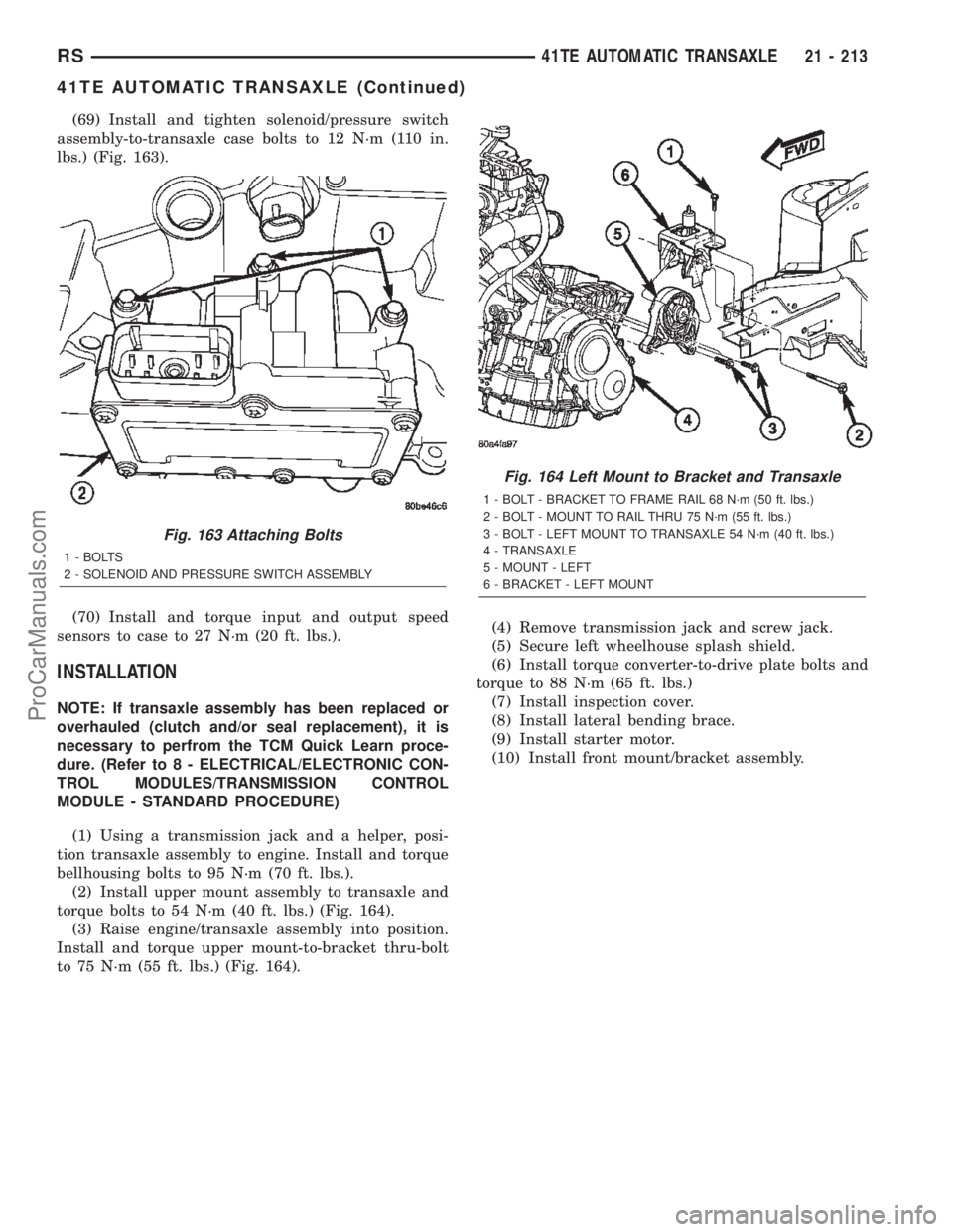
(69) Install and tighten solenoid/pressure switch
assembly-to-transaxle case bolts to 12 N´m (110 in.
lbs.) (Fig. 163).
(70) Install and torque input and output speed
sensors to case to 27 N´m (20 ft. lbs.).
INSTALLATION
NOTE: If transaxle assembly has been replaced or
overhauled (clutch and/or seal replacement), it is
necessary to perfrom the TCM Quick Learn proce-
dure. (Refer to 8 - ELECTRICAL/ELECTRONIC CON-
TROL MODULES/TRANSMISSION CONTROL
MODULE - STANDARD PROCEDURE)
(1) Using a transmission jack and a helper, posi-
tion transaxle assembly to engine. Install and torque
bellhousing bolts to 95 N´m (70 ft. lbs.).
(2) Install upper mount assembly to transaxle and
torque bolts to 54 N´m (40 ft. lbs.) (Fig. 164).
(3) Raise engine/transaxle assembly into position.
Install and torque upper mount-to-bracket thru-bolt
to 75 N´m (55 ft. lbs.) (Fig. 164).(4) Remove transmission jack and screw jack.
(5) Secure left wheelhouse splash shield.
(6) Install torque converter-to-drive plate bolts and
torque to 88 N´m (65 ft. lbs.)
(7) Install inspection cover.
(8) Install lateral bending brace.
(9) Install starter motor.
(10) Install front mount/bracket assembly.
Fig. 163 Attaching Bolts
1 - BOLTS
2 - SOLENOID AND PRESSURE SWITCH ASSEMBLY
Fig. 164 Left Mount to Bracket and Transaxle
1 - BOLT - BRACKET TO FRAME RAIL 68 N´m (50 ft. lbs.)
2 - BOLT - MOUNT TO RAIL THRU 75 N´m (55 ft. lbs.)
3 - BOLT - LEFT MOUNT TO TRANSAXLE 54 N´m (40 ft. lbs.)
4 - TRANSAXLE
5 - MOUNT - LEFT
6 - BRACKET - LEFT MOUNT
RS41TE AUTOMATIC TRANSAXLE21 - 213
41TE AUTOMATIC TRANSAXLE (Continued)
ProCarManuals.com
Page 1771 of 2399
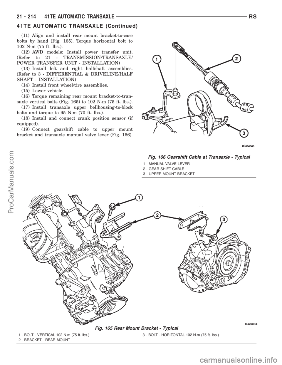
(11) Align and install rear mount bracket-to-case
bolts by hand (Fig. 165). Torque horizontal bolt to
102 N´m (75 ft. lbs.).
(12) AWD models: Install power transfer unit.
(Refer to 21 - TRANSMISSION/TRANSAXLE/
POWER TRANSFER UNIT - INSTALLATION)
(13) Install left and right halfshaft assemblies.
(Refer to 3 - DIFFERENTIAL & DRIVELINE/HALF
SHAFT - INSTALLATION)
(14) Install front wheel/tire assemblies.
(15) Lower vehicle.
(16) Torque remaining rear mount bracket-to-tran-
saxle vertical bolts (Fig. 165) to 102 N´m (75 ft. lbs.).
(17) Install transaxle upper bellhousing-to-block
bolts and torque to 95 N´m (70 ft. lbs.).
(18) Install and connect crank position sensor (if
equipped).
(19) Connect gearshift cable to upper mount
bracket and transaxle manual valve lever (Fig. 166).
Fig. 165 Rear Mount Bracket - Typical
1 - BOLT - VERTICAL 102 N´m (75 ft. lbs.)
2 - BRACKET - REAR MOUNT3 - BOLT - HORIZONTAL 102 N´m (75 ft. lbs.)
Fig. 166 Gearshift Cable at Transaxle - Typical
1 - MANUAL VALVE LEVER
2 - GEAR SHIFT CABLE
3 - UPPER MOUNT BRACKET
21 - 214 41TE AUTOMATIC TRANSAXLERS
41TE AUTOMATIC TRANSAXLE (Continued)
ProCarManuals.com
Page 1785 of 2399
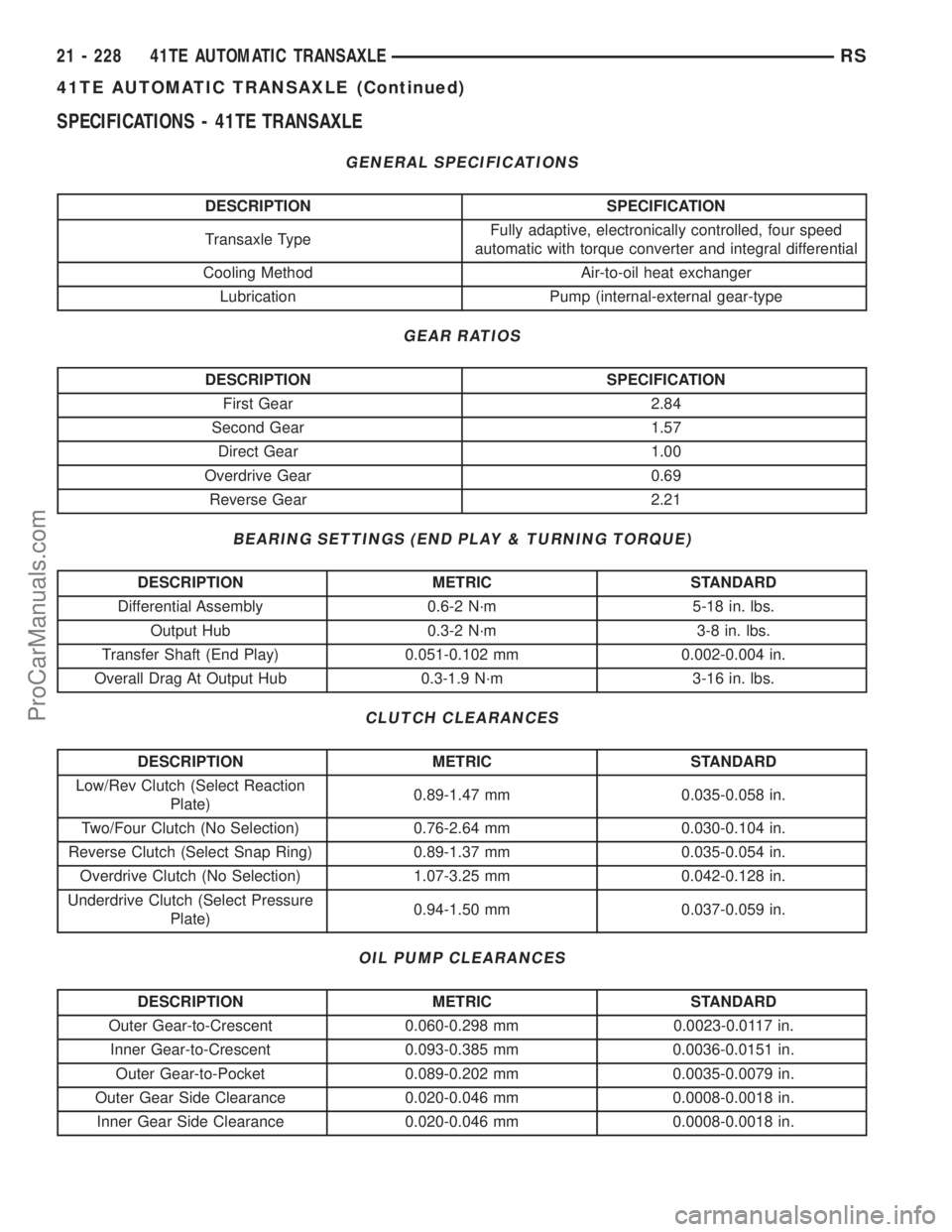
SPECIFICATIONS - 41TE TRANSAXLE
GENERAL SPECIFICATIONS
DESCRIPTION SPECIFICATION
Transaxle TypeFully adaptive, electronically controlled, four speed
automatic with torque converter and integral differential
Cooling Method Air-to-oil heat exchanger
Lubrication Pump (internal-external gear-type
GEAR RATIOS
DESCRIPTION SPECIFICATION
First Gear 2.84
Second Gear 1.57
Direct Gear 1.00
Overdrive Gear 0.69
Reverse Gear 2.21
BEARING SETTINGS (END PLAY & TURNING TORQUE)
DESCRIPTION METRIC STANDARD
Differential Assembly 0.6-2 N´m 5-18 in. lbs.
Output Hub 0.3-2 N´m 3-8 in. lbs.
Transfer Shaft (End Play) 0.051-0.102 mm 0.002-0.004 in.
Overall Drag At Output Hub 0.3-1.9 N´m 3-16 in. lbs.
CLUTCH CLEARANCES
DESCRIPTION METRIC STANDARD
Low/Rev Clutch (Select Reaction
Plate)0.89-1.47 mm 0.035-0.058 in.
Two/Four Clutch (No Selection) 0.76-2.64 mm 0.030-0.104 in.
Reverse Clutch (Select Snap Ring) 0.89-1.37 mm 0.035-0.054 in.
Overdrive Clutch (No Selection) 1.07-3.25 mm 0.042-0.128 in.
Underdrive Clutch (Select Pressure
Plate)0.94-1.50 mm 0.037-0.059 in.
OIL PUMP CLEARANCES
DESCRIPTION METRIC STANDARD
Outer Gear-to-Crescent 0.060-0.298 mm 0.0023-0.0117 in.
Inner Gear-to-Crescent 0.093-0.385 mm 0.0036-0.0151 in.
Outer Gear-to-Pocket 0.089-0.202 mm 0.0035-0.0079 in.
Outer Gear Side Clearance 0.020-0.046 mm 0.0008-0.0018 in.
Inner Gear Side Clearance 0.020-0.046 mm 0.0008-0.0018 in.
21 - 228 41TE AUTOMATIC TRANSAXLERS
41TE AUTOMATIC TRANSAXLE (Continued)
ProCarManuals.com
Page 1786 of 2399
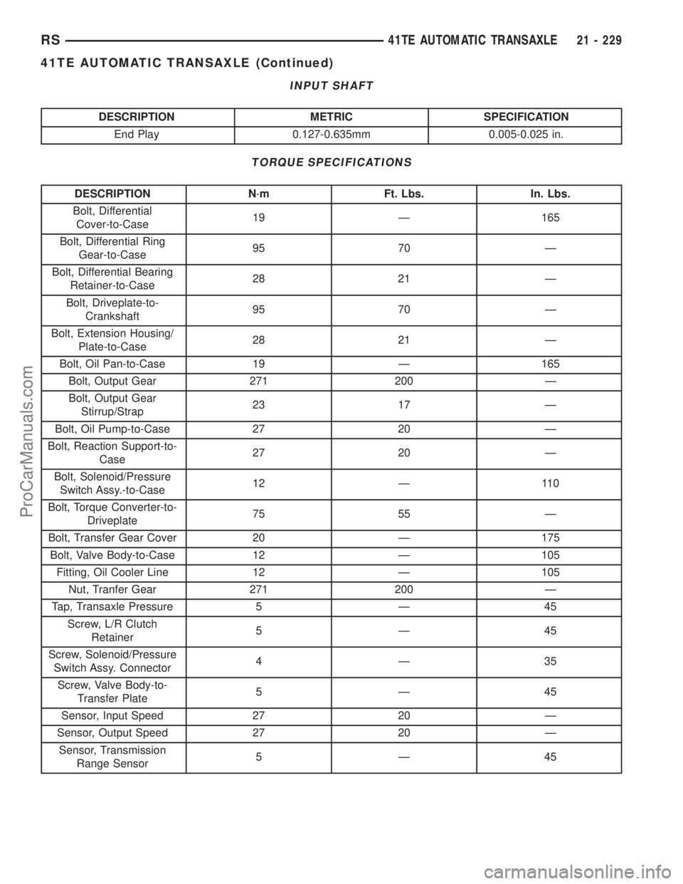
INPUT SHAFT
DESCRIPTION METRIC SPECIFICATION
End Play 0.127-0.635mm 0.005-0.025 in.
TORQUE SPECIFICATIONS
DESCRIPTION N´m Ft. Lbs. In. Lbs.
Bolt, Differential
Cover-to-Case19 Ð 165
Bolt, Differential Ring
Gear-to-Case95 70 Ð
Bolt, Differential Bearing
Retainer-to-Case28 21 Ð
Bolt, Driveplate-to-
Crankshaft95 70 Ð
Bolt, Extension Housing/
Plate-to-Case28 21 Ð
Bolt, Oil Pan-to-Case 19 Ð 165
Bolt, Output Gear 271 200 Ð
Bolt, Output Gear
Stirrup/Strap23 17 Ð
Bolt, Oil Pump-to-Case 27 20 Ð
Bolt, Reaction Support-to-
Case27 20 Ð
Bolt, Solenoid/Pressure
Switch Assy.-to-Case12 Ð 110
Bolt, Torque Converter-to-
Driveplate75 55 Ð
Bolt, Transfer Gear Cover 20 Ð 175
Bolt, Valve Body-to-Case 12 Ð 105
Fitting, Oil Cooler Line 12 Ð 105
Nut, Tranfer Gear 271 200 Ð
Tap, Transaxle Pressure 5 Ð 45
Screw, L/R Clutch
Retainer5Ð45
Screw, Solenoid/Pressure
Switch Assy. Connector4Ð35
Screw, Valve Body-to-
Transfer Plate5Ð45
Sensor, Input Speed 27 20 Ð
Sensor, Output Speed 27 20 Ð
Sensor, Transmission
Range Sensor5Ð45
RS41TE AUTOMATIC TRANSAXLE21 - 229
41TE AUTOMATIC TRANSAXLE (Continued)
ProCarManuals.com
Page 1795 of 2399
OPERATION
The three input clutches are responsible for driving
different components of the planetary geartrain.
NOTE: Refer to the ªElements In Useº chart in Diag-
nosis and Testing for a collective view of which
clutch elements are applied at each position of the
selector lever.
UNDERDRIVE CLUTCH
The underdrive clutch is hydraulically applied in
first, second, and third (direct) gears by pressurized
fluid against the underdrive piston. When the under-
drive clutch is applied, the underdrive hub drives the
rear sun gear.
OVERDRIVE CLUTCH
The overdrive clutch is hydraulically applied in
third (direct) and overdrive gears by pressurized fluid
against the overdrive/reverse piston. When the over-
drive clutch is applied, the overdrive hub drives the
front planet carrier.
REVERSE CLUTCH
The reverse clutch is hydraulically applied in
reverse gear only by pressurized fluid against the
overdrive/reverse piston. When the reverse clutch is
applied, the front sun gear assembly is driven.
FINAL DRIVE
DISASSEMBLY
NOTE: The differential is serviced as an assembly.
Differential service is limited to bearing cups and
cones. Any other differential component failure
must be remedied by differential assembly and
transfer shaft replacement.
The transfer shaft should be removed for differen-
tial repair and bearing turning torque checking.
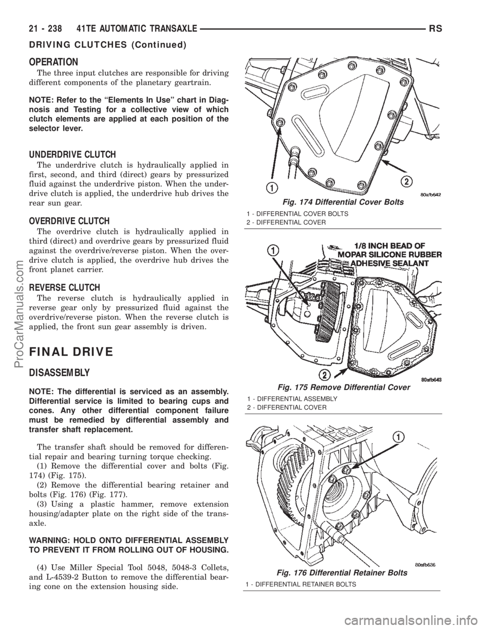
(1) Remove the differential cover and bolts (Fig.
174) (Fig. 175).
(2) Remove the differential bearing retainer and
bolts (Fig. 176) (Fig. 177).
(3) Using a plastic hammer, remove extension
housing/adapter plate on the right side of the trans-
axle.
WARNING: HOLD ONTO DIFFERENTIAL ASSEMBLY
TO PREVENT IT FROM ROLLING OUT OF HOUSING.
(4) Use Miller Special Tool 5048, 5048-3 Collets,
and L-4539-2 Button to remove the differential bear-
ing cone on the extension housing side.
Fig. 174 Differential Cover Bolts
1 - DIFFERENTIAL COVER BOLTS
2 - DIFFERENTIAL COVER
Fig. 175 Remove Differential Cover
1 - DIFFERENTIAL ASSEMBLY
2 - DIFFERENTIAL COVER
Fig. 176 Differential Retainer Bolts
1 - DIFFERENTIAL RETAINER BOLTS
21 - 238 41TE AUTOMATIC TRANSAXLERS
DRIVING CLUTCHES (Continued)
ProCarManuals.com
Page 1802 of 2399
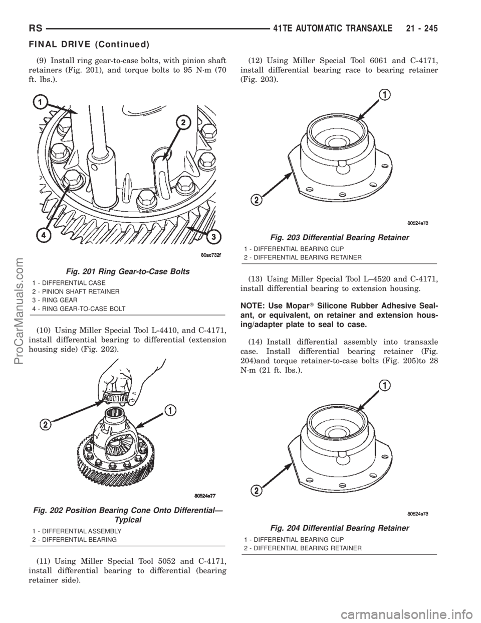
(9) Install ring gear-to-case bolts, with pinion shaft
retainers (Fig. 201), and torque bolts to 95 N´m (70
ft. lbs.).
(10) Using Miller Special Tool L-4410, and C-4171,
install differential bearing to differential (extension
housing side) (Fig. 202).
(11) Using Miller Special Tool 5052 and C-4171,
install differential bearing to differential (bearing
retainer side).(12) Using Miller Special Tool 6061 and C-4171,
install differential bearing race to bearing retainer
(Fig. 203).
(13) Using Miller Special Tool L±4520 and C-4171,
install differential bearing to extension housing.
NOTE: Use MoparTSilicone Rubber Adhesive Seal-
ant, or equivalent, on retainer and extension hous-
ing/adapter plate to seal to case.
(14) Install differential assembly into transaxle
case. Install differential bearing retainer (Fig.
204)and torque retainer-to-case bolts (Fig. 205)to 28
N´m (21 ft. lbs.).
Fig. 201 Ring Gear-to-Case Bolts
1 - DIFFERENTIAL CASE
2 - PINION SHAFT RETAINER
3 - RING GEAR
4 - RING GEAR-TO-CASE BOLT
Fig. 202 Position Bearing Cone Onto DifferentialÐ
Typical
1 - DIFFERENTIAL ASSEMBLY
2 - DIFFERENTIAL BEARING
Fig. 203 Differential Bearing Retainer
1 - DIFFERENTIAL BEARING CUP
2 - DIFFERENTIAL BEARING RETAINER
Fig. 204 Differential Bearing Retainer
1 - DIFFERENTIAL BEARING CUP
2 - DIFFERENTIAL BEARING RETAINER
RS41TE AUTOMATIC TRANSAXLE21 - 245
FINAL DRIVE (Continued)
ProCarManuals.com