2002 CHRYSLER CARAVAN service
[x] Cancel search: servicePage 2344 of 2399
INSTALLATION
(1) Remove the tape or plugs from the evaporator
tube fittings and both expansion valve ports.
(2) Lubricate new rubber O-ring seals with clean
refrigerant oil and install them on the evaporator
tube fittings.
(3) Position the expansion valve onto the evapora-
tor tubes.
(4) Install and tighten the two screws that secure
the expansion valve to the evaporator tube sealing
plate. Tighten the screws to 11 N´m (97 in. lbs.).
(5) Reinstall the rear evaporator line extension
onto the expansion valve. (Refer to 24 - HEATING &
AIR CONDITIONING/PLUMBING - REAR/EVAPO-
RATOR - INSTALLATION - EVAPORATOR LINE
EXTENSION).
(6) Install the foam insulator wrap over the rear
expansion valve.
(7) Reinstall the rear heater-A/C unit housing into
the vehicle. (Refer to 24 - HEATING & AIR CONDI-
TIONING/DISTRIBUTION - REAR/REAR HEATER-
A/C HOUSING - INSTALLATION).
(8) Run the HVAC Cooldown Test to verify proper
operation.
HEATER CORE
DESCRIPTION
The rear heater core is located near the front of
the rear heater-A/C unit housing, behind the right
rear wheel house. It is a heat exchanger made of
rows of tubes and fins. One end of the core is fitted
with a molded plastic tank that includes integral
heater core inlet and outlet nipples. The heater core
can be serviced without removing the rear heater-A/C
unit housing from the vehicle. The heater core cannot
be repaired and, if faulty or damaged, it must be
replaced.
OPERATION
Engine coolant is circulated through heater hoses
to the heater core at all times. As the coolant flows
through the heater core, heat removed from the
engine is transferred to the heater core fins and
tubes. Air directed through the heater core picks up
the heat from the heater core fins. The blend air door
allows control of the heater output air temperature
by controlling how much of the air flowing through
the rear heater-A/C unit housing is directed through
the heater core.
STANDARD PROCEDURE - HEATER CORE
FILLING
In its final installed position, the rear heater core
is positioned higher than the radiator fill cap. There-fore, when the cooling system is drained and refilled,
gravity will not refill the heater core with coolant to
the proper level. This may result in two problems:1.
Insufficient coolant level in the engine cooling sys-
tem, which may result in engine overheating.2.Air
entrapped within the rear heater core, which may
result in insufficient rear heater performance. There
are two methods that may be employed to prevent
these problems:1.Pre-filling of the rear heater core.
2.Thermal cycling of the engine cooling system. Fol-
lowing are descriptions of both prevention methods,
as well as a method to verify rear heater perfor-
mance.
WARNING: REFER TO THE APPLICABLE WARN-
INGS AND CAUTIONS FOR THIS SYSTEM BEFORE
PERFORMING THE FOLLOWING OPERATION.
(Refer to 24 - HEATING & AIR CONDITIONING/
PLUMBING FRONT - WARNING - HEATER PLUMB-
ING).
PRE-FILLING
If the rear heater core or the rear heater-A/C hous-
ing have been removed from the vehicle for service,
the rear heater core may be pre-filled with the proper
engine coolant mixture prior to reconnecting the
heater hoses to the heater core hose fittings.
(1) The heater core should be installed in the rear
heater-A/C unit housing, and the rear heater-A/C
unit housing should be installed in the vehicle.
(2) Take the proper precautions to protect the car-
peting below the rear heater core from spilled engine
coolant and have absorbent toweling readily avail-
able to mop up any spills.
(3) Insert the small end of an appropriate funnel
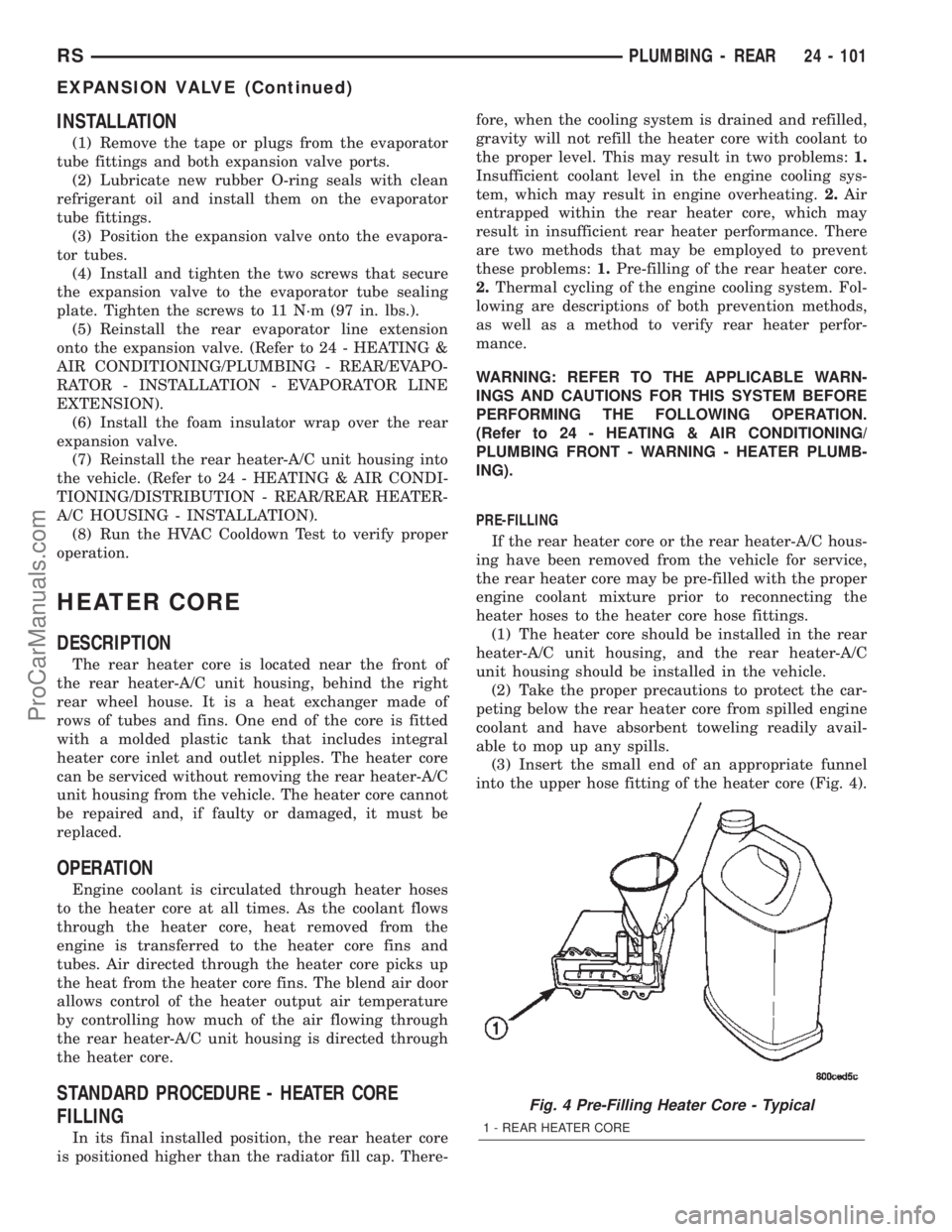
into the upper hose fitting of the heater core (Fig. 4).
Fig. 4 Pre-Filling Heater Core - Typical
1 - REAR HEATER CORE
RSPLUMBING - REAR24 - 101
EXPANSION VALVE (Continued)
ProCarManuals.com
Page 2346 of 2399
INSTALLATION
NOTE: If the rear heater core or the rear heater-A/C
housing have been removed from the vehicle for
service, the rear heater core may be pre-filled with
the proper engine coolant mixture prior to recon-
necting the heater hoses to the heater core hose fit-
tings. (Refer to 24 - HEATING & AIR CONDITIONING/
PLUMBING - REAR/HEATER CORE - STANDARD
PROCEDURE - HEATER CORE FILLING).
(1) Carefully slide the heater core into the rear
heater-A/C unit housing.
(2) Using hand pressure, press firmly and evenly
on the heater core end plate until the four latch tabs
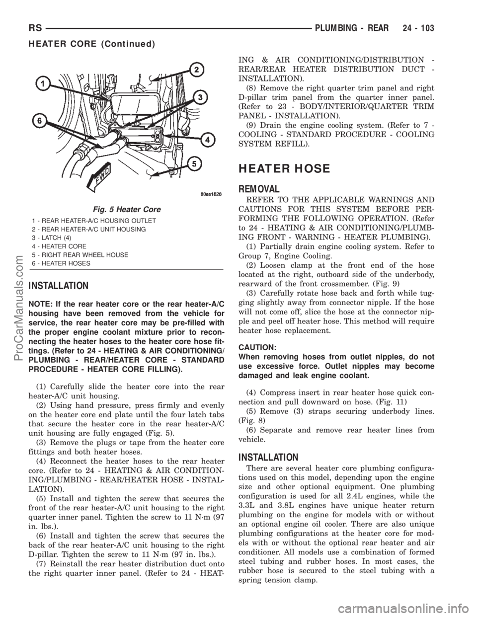
that secure the heater core in the rear heater-A/C
unit housing are fully engaged (Fig. 5).
(3) Remove the plugs or tape from the heater core
fittings and both heater hoses.
(4) Reconnect the heater hoses to the rear heater
core. (Refer to 24 - HEATING & AIR CONDITION-
ING/PLUMBING - REAR/HEATER HOSE - INSTAL-
LATION).
(5) Install and tighten the screw that secures the
front of the rear heater-A/C unit housing to the right
quarter inner panel. Tighten the screw to 11 N´m (97
in. lbs.).
(6) Install and tighten the screw that secures the
back of the rear heater-A/C unit housing to the right
D-pillar. Tighten the screw to 11 N´m (97 in. lbs.).
(7) Reinstall the rear heater distribution duct onto
the right quarter inner panel. (Refer to 24 - HEAT-ING & AIR CONDITIONING/DISTRIBUTION -
REAR/REAR HEATER DISTRIBUTION DUCT -
INSTALLATION).
(8) Remove the right quarter trim panel and right
D-pillar trim panel from the quarter inner panel.
(Refer to 23 - BODY/INTERIOR/QUARTER TRIM
PANEL - INSTALLATION).
(9) Drain the engine cooling system. (Refer to 7 -
COOLING - STANDARD PROCEDURE - COOLING
SYSTEM REFILL).
HEATER HOSE
REMOVAL
REFER TO THE APPLICABLE WARNINGS AND
CAUTIONS FOR THIS SYSTEM BEFORE PER-
FORMING THE FOLLOWING OPERATION. (Refer
to 24 - HEATING & AIR CONDITIONING/PLUMB-
ING FRONT - WARNING - HEATER PLUMBING).
(1) Partially drain engine cooling system. Refer to
Group 7, Engine Cooling.
(2) Loosen clamp at the front end of the hose
located at the right, outboard side of the underbody,
rearward of the front crossmember. (Fig. 9)
(3) Carefully rotate hose back and forth while tug-
ging slightly away from connector nipple. If the hose
will not come off, slice the hose at the connector nip-
ple and peel off heater hose. This method will require
heater hose replacement.
CAUTION:
When removing hoses from outlet nipples, do not
use excessive force. Outlet nipples may become
damaged and leak engine coolant.
(4) Compress insert in rear heater hose quick con-
nection and pull downward on hose. (Fig. 11)
(5) Remove (3) straps securing underbody lines.
(Fig. 8)
(6) Separate and remove rear heater lines from
vehicle.
INSTALLATION
There are several heater core plumbing configura-
tions used on this model, depending upon the engine
size and other optional equipment. One plumbing
configuration is used for all 2.4L engines, while the
3.3L and 3.8L engines have unique heater return
plumbing on the engine for models with or without
an optional engine oil cooler. There are also unique
plumbing configurations at the heater core for mod-
els with or without the optional rear heater and air
conditioner. All models use a combination of formed
steel tubing and rubber hoses. In most cases, the
rubber hose is secured to the steel tubing with a
spring tension clamp.
Fig. 5 Heater Core
1 - REAR HEATER-A/C HOUSING OUTLET
2 - REAR HEATER-A/C UNIT HOUSING
3 - LATCH (4)
4 - HEATER CORE
5 - RIGHT REAR WHEEL HOUSE
6 - HEATER HOSES
RSPLUMBING - REAR24 - 103
HEATER CORE (Continued)
ProCarManuals.com
Page 2347 of 2399
WARNING: REFER TO THE APPLICABLE WARN-
INGS AND CAUTIONS FOR THIS SYSTEM BEFORE
PERFORMING THE FOLLOWING OPERATION.
(Refer to 24 - HEATING & AIR CONDITIONING/
PLUMBING FRONT - WARNING - HEATER PLUMB-
ING).
(1) Using spring tension clamp pliers, compress
and slide the clamps that secure each end of the
heater hose toward the center of the hose being
installed. Release the clamp when it is near the cen-
ter of the hose.
(2) Grasp one end of the heater hose being
installed firmly and carefully twist the hose back and
forth while pushing it over from the barbed end of
the nipple. Repeat this procedure at the opposite end
of the hose being installed.
(3) Using spring tension clamp pliers, compress
and slide the clamps that secure each end of the
heater hose over the tube or nipple. Release the
clamp when it is over the tube or nipple.
(4) Refill the engine cooling system. (Refer to 7 -
COOLING - STANDARD PROCEDURE - COOLING
SYSTEM REFILL).
SUCTION LINE
REMOVAL
The front air conditioner suction line includes the
low side service port on a section of tubing located
near the compressor. On models equipped with the
optional rear air conditioner, the front air conditioner
suction line also includes a suction line hose and
tube extension that connects the front suction line to
the suction line for the rear air conditioner.
WARNING: REFER TO THE APPLICABLE WARN-
INGS AND CAUTIONS FOR THIS SYSTEM BEFORE
PERFORMING THE FOLLOWING OPERATION.
(Refer to 24 - HEATING & AIR CONDITIONING/
PLUMBING - FRONT - WARNING - A/C PLUMBING)
and (Refer to 24 - HEATING & AIR CONDITIONING/
PLUMBING - FRONT - CAUTION - A/C PLUMBING).
(1) Recover the refrigerant from the refrigerant
system. (Refer to 24 - HEATING & AIR CONDI-
TIONING/PLUMBING - FRONT/REFRIGERANT -
STANDARD PROCEDURE - REFRIGERANT
RECOVERY).
(2) Disconnect and isolate the battery negative
cable.
(3) Remove the air cleaner top cover and snorkel
from the air cleaner housing located on the right side
of the engine compartment.(4) Disconnect the drain tube from the wiper mod-
ule drain on the right side of the engine compart-
ment.
(5) Remove the nut that secures the suction line
fitting to the top of the compressor.
(6) Disconnect the suction line fitting from the
compressor suction port.
(7) Remove the seal from the suction line fitting
and discard.
(8) Install plugs in, or tape over the opened suc-
tion line fitting and the compressor suction port.
(9) Disengage the retainer that secures the suction
line routing clip to the filter-drier mounting bracket
on the side of the right front strut tower in the
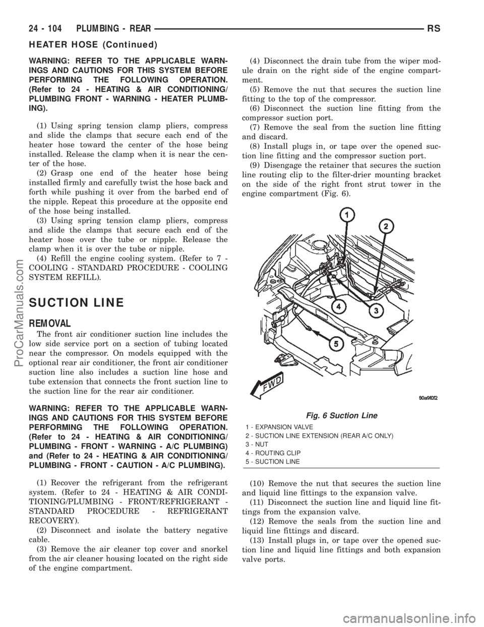
engine compartment (Fig. 6).
(10) Remove the nut that secures the suction line
and liquid line fittings to the expansion valve.
(11) Disconnect the suction line and liquid line fit-
tings from the expansion valve.
(12) Remove the seals from the suction line and
liquid line fittings and discard.
(13) Install plugs in, or tape over the opened suc-
tion line and liquid line fittings and both expansion
valve ports.
Fig. 6 Suction Line
1 - EXPANSION VALVE
2 - SUCTION LINE EXTENSION (REAR A/C ONLY)
3 - NUT
4 - ROUTING CLIP
5 - SUCTION LINE
24 - 104 PLUMBING - REARRS
HEATER HOSE (Continued)
ProCarManuals.com
Page 2348 of 2399
(14) If the vehicle is equipped with the optional
rear air conditioner, go to Step 15. If the vehicle does
not have the optional rear air conditioner, go to Step
21.
(15) Raise and support the vehicle.
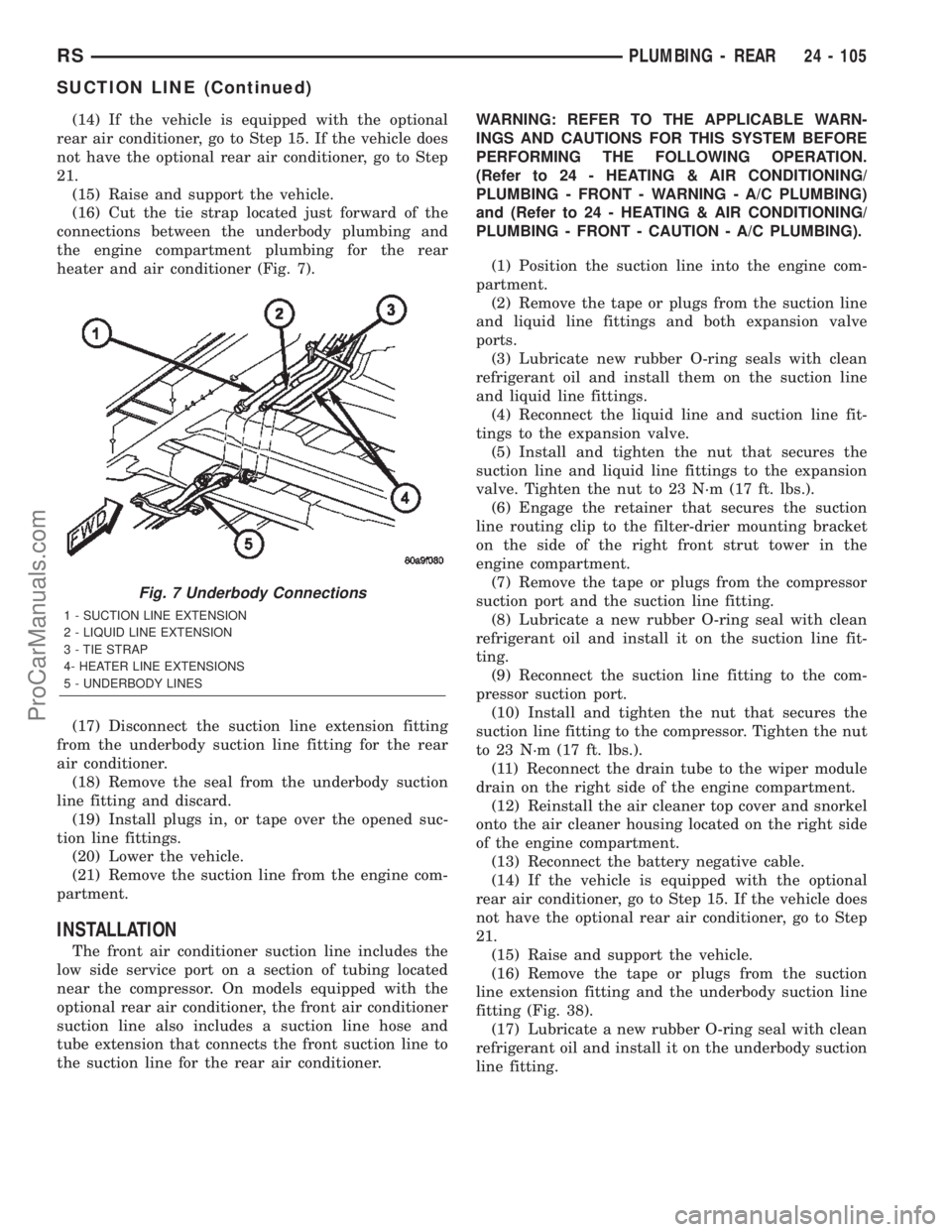
(16) Cut the tie strap located just forward of the
connections between the underbody plumbing and
the engine compartment plumbing for the rear
heater and air conditioner (Fig. 7).
(17) Disconnect the suction line extension fitting
from the underbody suction line fitting for the rear
air conditioner.
(18) Remove the seal from the underbody suction
line fitting and discard.
(19) Install plugs in, or tape over the opened suc-
tion line fittings.
(20) Lower the vehicle.
(21) Remove the suction line from the engine com-
partment.
INSTALLATION
The front air conditioner suction line includes the
low side service port on a section of tubing located
near the compressor. On models equipped with the
optional rear air conditioner, the front air conditioner
suction line also includes a suction line hose and
tube extension that connects the front suction line to
the suction line for the rear air conditioner.WARNING: REFER TO THE APPLICABLE WARN-
INGS AND CAUTIONS FOR THIS SYSTEM BEFORE
PERFORMING THE FOLLOWING OPERATION.
(Refer to 24 - HEATING & AIR CONDITIONING/
PLUMBING - FRONT - WARNING - A/C PLUMBING)
and (Refer to 24 - HEATING & AIR CONDITIONING/
PLUMBING - FRONT - CAUTION - A/C PLUMBING).
(1) Position the suction line into the engine com-
partment.
(2) Remove the tape or plugs from the suction line
and liquid line fittings and both expansion valve
ports.
(3) Lubricate new rubber O-ring seals with clean
refrigerant oil and install them on the suction line
and liquid line fittings.
(4) Reconnect the liquid line and suction line fit-
tings to the expansion valve.
(5) Install and tighten the nut that secures the
suction line and liquid line fittings to the expansion
valve. Tighten the nut to 23 N´m (17 ft. lbs.).
(6) Engage the retainer that secures the suction
line routing clip to the filter-drier mounting bracket
on the side of the right front strut tower in the
engine compartment.
(7) Remove the tape or plugs from the compressor
suction port and the suction line fitting.
(8) Lubricate a new rubber O-ring seal with clean
refrigerant oil and install it on the suction line fit-
ting.
(9) Reconnect the suction line fitting to the com-
pressor suction port.
(10) Install and tighten the nut that secures the
suction line fitting to the compressor. Tighten the nut
to 23 N´m (17 ft. lbs.).
(11) Reconnect the drain tube to the wiper module
drain on the right side of the engine compartment.
(12) Reinstall the air cleaner top cover and snorkel
onto the air cleaner housing located on the right side
of the engine compartment.
(13) Reconnect the battery negative cable.
(14) If the vehicle is equipped with the optional
rear air conditioner, go to Step 15. If the vehicle does
not have the optional rear air conditioner, go to Step
21.
(15) Raise and support the vehicle.
(16) Remove the tape or plugs from the suction
line extension fitting and the underbody suction line
fitting (Fig. 38).
(17) Lubricate a new rubber O-ring seal with clean
refrigerant oil and install it on the underbody suction
line fitting.
Fig. 7 Underbody Connections
1 - SUCTION LINE EXTENSION
2 - LIQUID LINE EXTENSION
3 - TIE STRAP
4- HEATER LINE EXTENSIONS
5 - UNDERBODY LINES
RSPLUMBING - REAR24 - 105
SUCTION LINE (Continued)
ProCarManuals.com
Page 2349 of 2399
(18) Reconnect the suction line extension fitting to
the underbody suction line fitting. Tighten the fit-
tings to 23 N´m (17 ft. lbs.).
(19) Install a new tie strap just forward of the con-
nections between the underbody plumbing and the
engine compartment plumbing for the rear heater
and air conditioner.
(20) Lower the vehicle.
(21) Evacuate the refrigerant system. (Refer to 24
- HEATING & AIR CONDITIONING/PLUMBING -
FRONT/REFRIGERANT - STANDARD PROCE-
DURE - REFRIGERANT SYSTEM EVACUATE).
(22) Charge the refrigerant system. (Refer to 24 -
HEATING & AIR CONDITIONING/PLUMBING -
FRONT/REFRIGERANT - STANDARD PROCE-
DURE - REFRIGERANT SYSTEM CHARGE).
UNDERBODY LINES
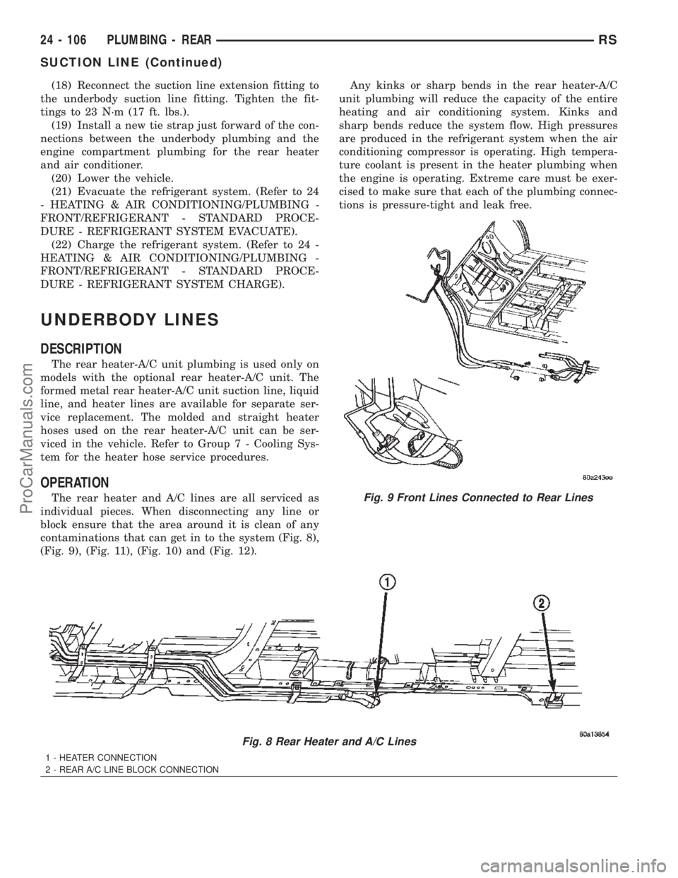
DESCRIPTION
The rear heater-A/C unit plumbing is used only on
models with the optional rear heater-A/C unit. The
formed metal rear heater-A/C unit suction line, liquid
line, and heater lines are available for separate ser-
vice replacement. The molded and straight heater
hoses used on the rear heater-A/C unit can be ser-
viced in the vehicle. Refer to Group 7 - Cooling Sys-
tem for the heater hose service procedures.
OPERATION
The rear heater and A/C lines are all serviced as
individual pieces. When disconnecting any line or
block ensure that the area around it is clean of any
contaminations that can get in to the system (Fig. 8),
(Fig. 9), (Fig. 11), (Fig. 10) and (Fig. 12).Any kinks or sharp bends in the rear heater-A/C
unit plumbing will reduce the capacity of the entire
heating and air conditioning system. Kinks and
sharp bends reduce the system flow. High pressures
are produced in the refrigerant system when the air
conditioning compressor is operating. High tempera-
ture coolant is present in the heater plumbing when
the engine is operating. Extreme care must be exer-
cised to make sure that each of the plumbing connec-
tions is pressure-tight and leak free.
Fig. 8 Rear Heater and A/C Lines
1 - HEATER CONNECTION
2 - REAR A/C LINE BLOCK CONNECTION
Fig. 9 Front Lines Connected to Rear Lines
24 - 106 PLUMBING - REARRS
SUCTION LINE (Continued)
ProCarManuals.com
Page 2353 of 2399
DIAGNOSIS AND TESTING - DIESEL
SUPPLEMENTAL HEATER - DCHA
The following table lists possible fault symptoms of
diesel fueled heaters.
SYMPTOM POSSIBLE CAUSES
Smell of diesel fuel Check heater system integration in vehicle's fuel system. Check fuel
lines for leakage, kinks or obstructions. If OK, Inspect the inlet muffler,
drain as necessary. Re-test the unit and re-inspect. Inspect the
exhaust tube and heater unit for the presence of external fuel. If a
volume is observed on the unit or in the exhaust tube or after draining
and testing. Remove heater unit from vehicle and repair or replace
components as required.
Heater does not achieve full load
operation.Check heater operation with DRB-III and replace components as
required.
Continuous white smoke from heater
exhaust during combustion operation.Check heater operation with DRB-III and replace components as
required. White smoke is typical in extreme weather conditions.
Heater can not be switched off. Check heater operation with DRB-III and replace components as
required.
Heater does not operate. Diagnosis cabin heater ECU using the DRB-III and the procedures
listed in Vehicle Performance under Cabin Heater Diagnosis in Group
18.
Loss of coolant (Leakage) or heater
develops smoke during combustion
operation and exhaust has an
extremely sweet smell.Inspect coolant hoses for leakage, kinks or loose hose connection.
Inspect the exhaust tube assembly for continuous flow, if OK there is
an internal heater leak and unit should be inspected and components
should be replaced as required.
Loss of fuel (dripping). Check heater system integration in vehicles fuel system. Check fuel
line connection for leakage. If OK there is an internal leak and unit
should be inspected and replaced as required.
EXHAUST TUBE
REMOVAL
WARNING: THERE IS A POTENTIAL DANGER OF
SKIN BURNS AS THE HEATER AND ITS COMPO-
NENTS MAY BE VERY HOT. MAKE SURE THE
HEATER IS ALLOWED TO COOL DOWN BEFORE
ANY SERVICE WORK IS ATTEMPTED.
WARNING: THERE IS A POTENTIAL DANGER OF
SKIN BURNS AS THE EXHAUST SYSTEM MAY BE
VERY HOT. MAKE SURE THE EXHAUST SYSTEM IS
ALLOWED TO COOL DOWN BEFORE ANY SERVICE
WORK IS ATTEMPTED ON THE CABIN HEATER.
(1) Elevate vehicle on a lift taking note of the
exhaust tube flexible section.
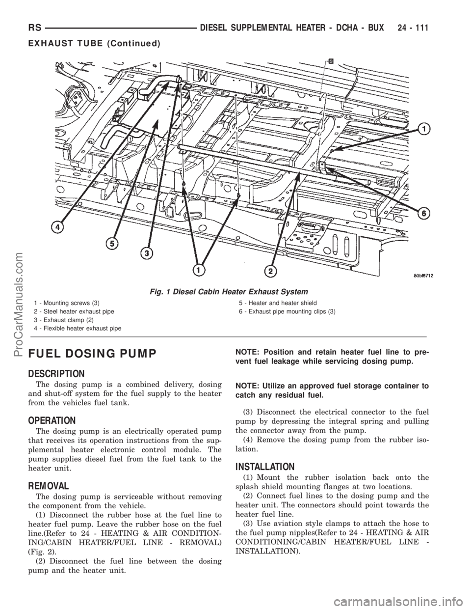
(2) Remove the exhaust clamp at the flexible pipe
and steel pipe connection (Fig. 1).
(3) Remove the clamp at the flexible pipe connec-
tion and the heater unit housing (if required).(4) Remove the three screws holding the exhaust
pipe to the body.
(5) Remove the steel exhaust pipe from the vehi-
cle.
(6) Remove the flexible exhaust pipe from the
vehicle (if required).
INSTALLATION
(1) Install the flexible exhaust pipe to the heater
unit. Tighten mounting clamp.
(2) Position the steel exhaust pipe to the flexible
exhaust and install and tighten the mounting clamp.
(3) Install the three exhaust pipe screws, adjust
pipe placement as needed and tighten the screws.
(4) Install the clamp to connect the steel exhaust
pipe to the flexible exhaust pipe and tighten clamp.
(5) Check exhaust pipe exhaust end placement and
make any final adjustments.
(6) Lower vehicle from lift.
24 - 110 DIESEL SUPPLEMENTAL HEATER - DCHA - BUXRS
DIESEL SUPPLEMENTAL HEATER - DCHA - BUX (Continued)
ProCarManuals.com
Page 2354 of 2399
FUEL DOSING PUMP
DESCRIPTION
The dosing pump is a combined delivery, dosing
and shut-off system for the fuel supply to the heater
from the vehicles fuel tank.
OPERATION
The dosing pump is an electrically operated pump
that receives its operation instructions from the sup-
plemental heater electronic control module. The
pump supplies diesel fuel from the fuel tank to the
heater unit.
REMOVAL
The dosing pump is serviceable without removing
the component from the vehicle.
(1) Disconnect the rubber hose at the fuel line to
heater fuel pump. Leave the rubber hose on the fuel
line.(Refer to 24 - HEATING & AIR CONDITION-
ING/CABIN HEATER/FUEL LINE - REMOVAL)
(Fig. 2).
(2) Disconnect the fuel line between the dosing
pump and the heater unit.NOTE: Position and retain heater fuel line to pre-
vent fuel leakage while servicing dosing pump.
NOTE: Utilize an approved fuel storage container to
catch any residual fuel.
(3) Disconnect the electrical connector to the fuel
pump by depressing the integral spring and pulling
the connector away from the pump.
(4) Remove the dosing pump from the rubber iso-
lation.
INSTALLATION
(1) Mount the rubber isolation back onto the
splash shield mounting flanges at two locations.
(2) Connect fuel lines to the dosing pump and the
heater unit. The connectors should point towards the
heater fuel line.
(3) Use aviation style clamps to attach the hose to
the fuel pump nipples(Refer to 24 - HEATING & AIR
CONDITIONING/CABIN HEATER/FUEL LINE -
INSTALLATION).
Fig. 1 Diesel Cabin Heater Exhaust System
1 - Mounting screws (3)
2 - Steel heater exhaust pipe
3 - Exhaust clamp (2)
4 - Flexible heater exhaust pipe5 - Heater and heater shield
6 - Exhaust pipe mounting clips (3)
RSDIESEL SUPPLEMENTAL HEATER - DCHA - BUX24 - 111
EXHAUST TUBE (Continued)
ProCarManuals.com
Page 2357 of 2399
(7) With the DRBIIItin Cabin Heater, select Sys-
tem Tests and Dosing Pump Prime. Allow the Dosing
Pump to run for the full 45 second cycle time. When
the 45 second cycle is complete, press Page Back on
the DRBIIItkey pad to exit the Dosing Pump Prime.
The Dosing Pump priming procedure is now com-
plete.
HEATER UNIT
REMOVAL
WARNING: ALLOW THE DCHA TO COOL BEFORE
PERFORMING A COMPONENT INSPECTION/REPAIR
OR REPLACEMENT. FAILURE TO FOLLOW THESE
INSTRUCTIONS MAY RESULT IN PERSONAL
INJURY.
WARNING: ALLOW THE EXHAUST SYSTEM TO
COOL BEFORE PERFORMING A COMPONENT
INSPECTION/REPAIR OR REPLACEMENT. FAILURE
TO FOLLOW THESE INSTRUCTION MAY RESULT IN
PERSONAL INJURY.
(1) Elevate the vehicle on a hoist/lift taking note of
heater exhaust tube flexible section.
(2) Drain cooling system(Refer to 7 - COOLING -
STANDARD PROCEDURE).
(3) Carefully open one hose to the underbody tube
assembly and drain the remaining coolant. A salvage
hose is a good idea to control the residual coolant, as
flow will occur from both the heater and the hose and
tube assemblies.
(4) Remove the second hose from the underbody
hose and tube assembly.
(5) Loosen the hose and tube assembly from the
toe-board cross member at two locations.
(6) Disconnect the electrical connector from the
body harness near the toe board cross member and
rail.
(7) Remove the wiring harness from the toe board
cross member(Refer to 24 - HEATING & AIR CON-
DITIONING/CABIN HEATER/HEATER UNIT -
REMOVAL).
(8) Open the fuel fill cap. Disconnect the rubber
fuel hose between the body tube assembly and the
fuel pump nipple at the body tube joint. A minimal
amount of fuel may flow from the open port.
NOTE: Utilize an approved fuel storage container to
catch any residual fuel.
(9) Loosen the two M8 fasteners at the rail. Take
care to notice that the exhaust tube bracket tab is on
top of the heater bracket.(10) Remove the heater exhaust tube flex section
from the exhaust tube by loosening the M6 bolt of
the clamp assembly. Remove the hose from the
exhaust tube. Removal of the rail tube assembly may
aid in this service operation.(Refer to 24 - HEATING
& AIR CONDITIONING/CABIN HEATER/EXHAUST
TUBE - REMOVAL).
(11) Remove seat hex nut at the heater mounting
flange to cross member.
(12) Loosen the remaining M6 and M8 fasteners
which mount the exhaust tube assembly to the vehi-
cle.
(a) Install a suitable cabin heater support device
under the cabin heater and secure the cabin heater
to the device.
(13) Loosen the remaining three M6 fasteners to
the cross members.
(14) Remove the loosened fasteners that support
the heater while supporting the weight of the heater.
(15) Swing the unit mounting bracket from
between the exhaust bracket and rail mounting loca-
tion. Drain any residual coolant from the heater unit.
(16) Lower the cabin heater and remove from the
supporting device and place on a suitable work area.
INSTALLATION
(1) Install the unit mounting bracket between the
exhaust bracket and the rail mounting location.
(2) Install the fasteners that support the heater
while supporting the weight of the heater.
(3) Install the three M6 fasteners to the cross
members. Tighten the M6 fasteners to 7 Nm (5 ft.
lbs.).
(4) Tighten the remaining M6 fasteners to 7 Nm (5
ft. lbs.) and the M8 fasteners to 23 Nm (17 ft. lbs.)
which mount the exhaust tube assembly to the vehi-
cle.
(5) Install the seat hex nut at the heater mounting
flange to the cross members. Tighten to 60 Nm (44 ft.
lbs.)
(6) Install the heater exhaust tube flex section to
the exhaust tube by tightening the M6 bolt of the
clamp assembly. Install the hose to the exhaust tube.
(7) Tighten the two M8 fasteners at the rail to 23
Nm (17 ft. lbs.). Taking care so that the exhaust tube
bracket tab is on the top of the heater bracket.
(8) Install the wiring harness(Refer to 24 - HEAT-
ING & AIR CONDITIONING/CABIN HEATER/
HEATER UNIT - INSTALLATION).
(9) Tighten the hose and tube assembly to the toe-
board cross member at two locations.
(10) Install the second hose to the underbody hose
and tube assembly.
(11) Connect the rubber fuel hose between the
body tube assembly and the fuel pump nipple at the
body tube joint. Close the fuel fill cap.
24 - 114 DIESEL SUPPLEMENTAL HEATER - DCHA - BUXRS
FUEL LINE (Continued)
ProCarManuals.com