2002 CHRYSLER CARAVAN lock
[x] Cancel search: lockPage 1268 of 2399
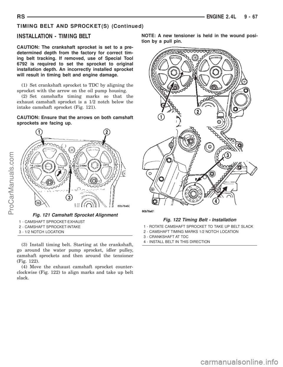
INSTALLATION - TIMING BELT
CAUTION: The crankshaft sprocket is set to a pre-
determined depth from the factory for correct tim-
ing belt tracking. If removed, use of Special Tool
6792 is required to set the sprocket to original
installation depth. An incorrectly installed sprocket
will result in timing belt and engine damage.
(1) Set crankshaft sprocket to TDC by aligning the
sprocket with the arrow on the oil pump housing.
(2) Set camshafts timing marks so that the
exhaust camshaft sprocket is a 1/2 notch below the
intake camshaft sprocket (Fig. 121).
CAUTION: Ensure that the arrows on both camshaft
sprockets are facing up.
(3) Install timing belt. Starting at the crankshaft,
go around the water pump sprocket, idler pulley,
camshaft sprockets and then around the tensioner
(Fig. 122).
(4) Move the exhaust camshaft sprocket counter-
clockwise (Fig. 122) to align marks and take up belt
slack.NOTE: A new tensioner is held in the wound posi-
tion by a pull pin.
Fig. 121 Camshaft Sprocket Alignment
1 - CAMSHAFT SPROCKET-EXHAUST
2 - CAMSHAFT SPROCKET-INTAKE
3 - 1/2 NOTCH LOCATIONFig. 122 Timing Belt - Installation
1 - ROTATE CAMSHAFT SPROCKET TO TAKE UP BELT SLACK
2 - CAMSHAFT TIMING MARKS 1/2 NOTCH LOCATION
3 - CRANKSHAFT AT TDC
4 - INSTALL BELT IN THIS DIRECTION
RSENGINE 2.4L9-67
TIMING BELT AND SPROCKET(S) (Continued)
ProCarManuals.com
Page 1269 of 2399
(5) Remove the pull pin or Allen wrench from the
belt tensioner.
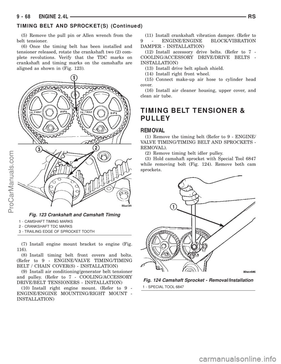
(6) Once the timing belt has been installed and
tensioner released, rotate the crankshaft two (2) com-
plete revolutions. Verify that the TDC marks on
crankshaft and timing marks on the camshafts are
aligned as shown in (Fig. 123).
(7) Install engine mount bracket to engine (Fig.
116).
(8) Install timing belt front covers and bolts.
(Refer to 9 - ENGINE/VALVE TIMING/TIMING
BELT / CHAIN COVER(S) - INSTALLATION)
(9) Install air conditioning/generator belt tensioner
and pulley. (Refer to 7 - COOLING/ACCESSORY
DRIVE/BELT TENSIONERS - INSTALLATION)
(10) Install right engine mount. (Refer to 9 -
ENGINE/ENGINE MOUNTING/RIGHT MOUNT -
INSTALLATION)(11) Install crankshaft vibration damper. (Refer to
9 - ENGINE/ENGINE BLOCK/VIBRATION
DAMPER - INSTALLATION)
(12) Install accessory drive belts. (Refer to 7 -
COOLING/ACCESSORY DRIVE/DRIVE BELTS -
INSTALLATION)
(13) Install drive belt splash shield.
(14) Install right front wheel.
(15) Connect make-up air hose to cylinder head
cover.
(16) Install air cleaner housing, upper cover, and
clean air tube.
TIMING BELT TENSIONER &
PULLEY
REMOVAL
(1) Remove the timing belt (Refer to 9 - ENGINE/
VALVE TIMING/TIMING BELT AND SPROCKETS -
REMOVAL).
(2) Remove timing belt idler pulley.
(3) Hold camshaft sprocket with Special Tool 6847
while removing bolt (Fig. 124). Remove both cam
sprockets.
Fig. 123 Crankshaft and Camshaft Timing
1 - CAMSHAFT TIMING MARKS
2 - CRANKSHAFT TDC MARKS
3 - TRAILING EDGE OF SPROCKET TOOTH
Fig. 124 Camshaft Sprocket - Removal/Installation
1 - SPECIAL TOOL 6847
9 - 68 ENGINE 2.4LRS
TIMING BELT AND SPROCKET(S) (Continued)
ProCarManuals.com
Page 1270 of 2399
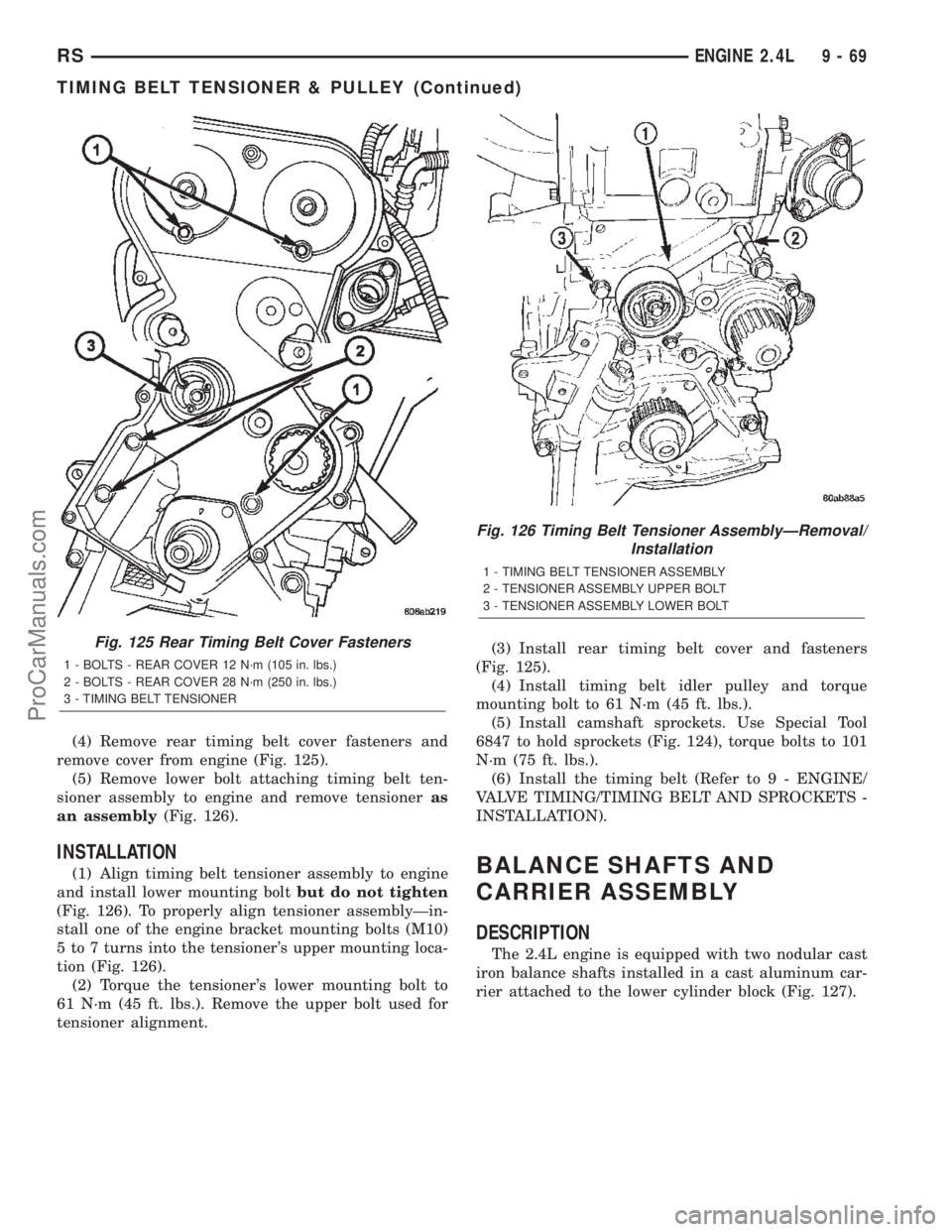
(4) Remove rear timing belt cover fasteners and
remove cover from engine (Fig. 125).
(5) Remove lower bolt attaching timing belt ten-
sioner assembly to engine and remove tensioneras
an assembly(Fig. 126).
INSTALLATION
(1) Align timing belt tensioner assembly to engine
and install lower mounting boltbut do not tighten
(Fig. 126). To properly align tensioner assemblyÐin-
stall one of the engine bracket mounting bolts (M10)
5 to 7 turns into the tensioner's upper mounting loca-
tion (Fig. 126).
(2) Torque the tensioner's lower mounting bolt to
61 N´m (45 ft. lbs.). Remove the upper bolt used for
tensioner alignment.(3) Install rear timing belt cover and fasteners
(Fig. 125).
(4) Install timing belt idler pulley and torque
mounting bolt to 61 N´m (45 ft. lbs.).
(5) Install camshaft sprockets. Use Special Tool
6847 to hold sprockets (Fig. 124), torque bolts to 101
N´m (75 ft. lbs.).
(6) Install the timing belt (Refer to 9 - ENGINE/
VALVE TIMING/TIMING BELT AND SPROCKETS -
INSTALLATION).BALANCE SHAFTS AND
CARRIER ASSEMBLY
DESCRIPTION
The 2.4L engine is equipped with two nodular cast
iron balance shafts installed in a cast aluminum car-
rier attached to the lower cylinder block (Fig. 127).
Fig. 125 Rear Timing Belt Cover Fasteners
1 - BOLTS - REAR COVER 12 N´m (105 in. lbs.)
2 - BOLTS - REAR COVER 28 N´m (250 in. lbs.)
3 - TIMING BELT TENSIONER
Fig. 126 Timing Belt Tensioner AssemblyÐRemoval/
Installation
1 - TIMING BELT TENSIONER ASSEMBLY
2 - TENSIONER ASSEMBLY UPPER BOLT
3 - TENSIONER ASSEMBLY LOWER BOLT
RSENGINE 2.4L9-69
TIMING BELT TENSIONER & PULLEY (Continued)
ProCarManuals.com
Page 1274 of 2399
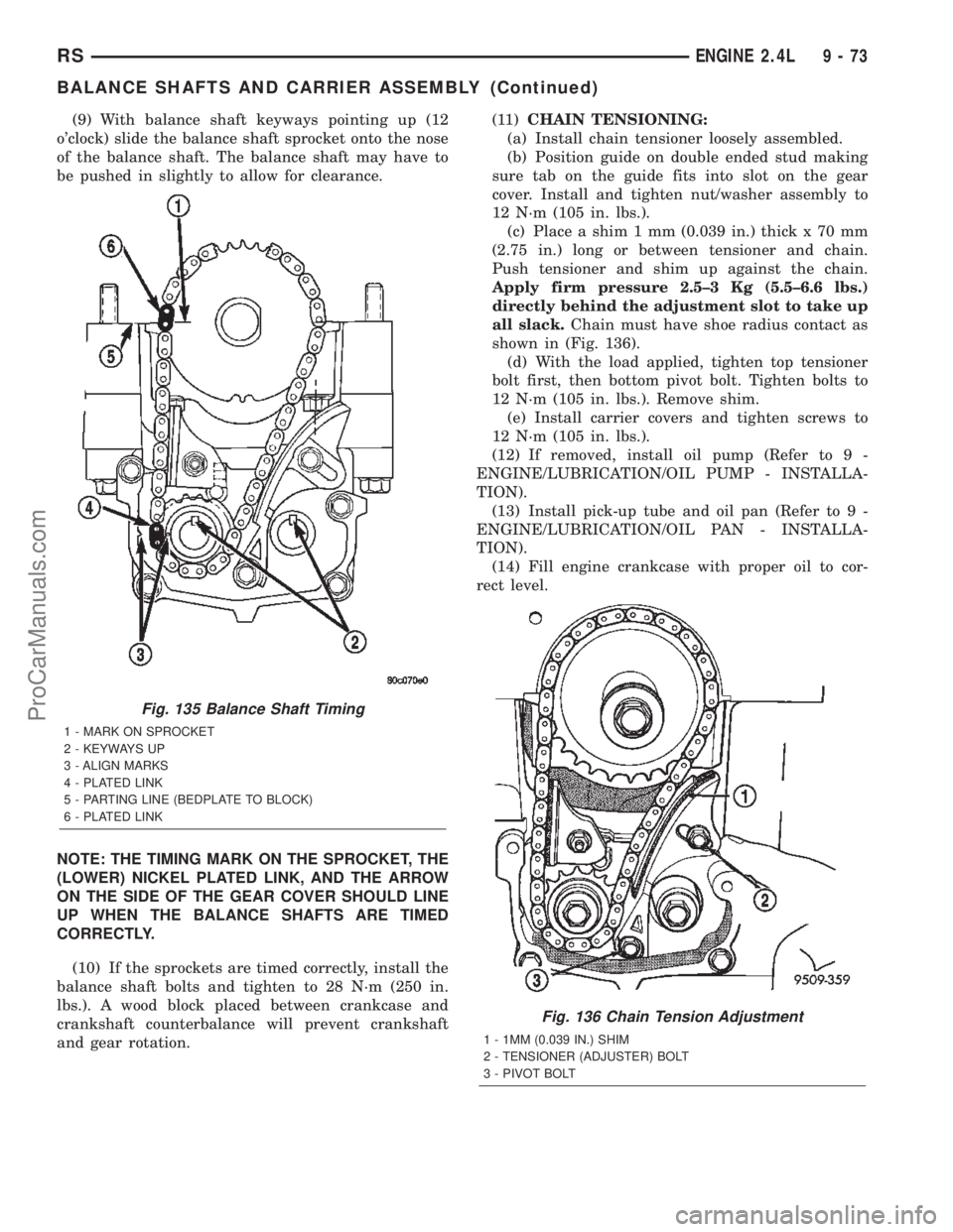
(9) With balance shaft keyways pointing up (12
o'clock) slide the balance shaft sprocket onto the nose
of the balance shaft. The balance shaft may have to
be pushed in slightly to allow for clearance.
NOTE: THE TIMING MARK ON THE SPROCKET, THE
(LOWER) NICKEL PLATED LINK, AND THE ARROW
ON THE SIDE OF THE GEAR COVER SHOULD LINE
UP WHEN THE BALANCE SHAFTS ARE TIMED
CORRECTLY.
(10) If the sprockets are timed correctly, install the
balance shaft bolts and tighten to 28 N´m (250 in.
lbs.). A wood block placed between crankcase and
crankshaft counterbalance will prevent crankshaft
and gear rotation.(11)CHAIN TENSIONING:
(a) Install chain tensioner loosely assembled.
(b) Position guide on double ended stud making
sure tab on the guide fits into slot on the gear
cover. Install and tighten nut/washer assembly to
12 N´m (105 in. lbs.).
(c) Place a shim 1 mm (0.039 in.) thick x 70 mm
(2.75 in.) long or between tensioner and chain.
Push tensioner and shim up against the chain.
Apply firm pressure 2.5±3 Kg (5.5±6.6 lbs.)
directly behind the adjustment slot to take up
all slack.Chain must have shoe radius contact as
shown in (Fig. 136).
(d) With the load applied, tighten top tensioner
bolt first, then bottom pivot bolt. Tighten bolts to
12 N´m (105 in. lbs.). Remove shim.
(e) Install carrier covers and tighten screws to
12 N´m (105 in. lbs.).
(12) If removed, install oil pump (Refer to 9 -
ENGINE/LUBRICATION/OIL PUMP - INSTALLA-
TION).
(13) Install pick-up tube and oil pan (Refer to 9 -
ENGINE/LUBRICATION/OIL PAN - INSTALLA-
TION).
(14) Fill engine crankcase with proper oil to cor-
rect level.
Fig. 135 Balance Shaft Timing
1 - MARK ON SPROCKET
2 - KEYWAYS UP
3 - ALIGN MARKS
4 - PLATED LINK
5 - PARTING LINE (BEDPLATE TO BLOCK)
6 - PLATED LINK
Fig. 136 Chain Tension Adjustment
1 - 1MM (0.039 IN.) SHIM
2 - TENSIONER (ADJUSTER) BOLT
3 - PIVOT BOLT
RSENGINE 2.4L9-73
BALANCE SHAFTS AND CARRIER ASSEMBLY (Continued)
ProCarManuals.com
Page 1275 of 2399
ENGINE 3.3/3.8L
TABLE OF CONTENTS
page page
ENGINE 3.3/3.8L
DESCRIPTION.........................76
DIAGNOSIS AND TESTING
DIAGNOSIS AND TESTING - ENGINE
DIAGNOSIS - INTRODUCTION...........77
DIAGNOSIS AND TESTING - ENGINE
DIAGNOSIS - PERFORMANCE...........78
DIAGNOSIS AND TESTING - ENGINE
DIAGNOSIS - MECHANICAL.............80
DIAGNOSIS AND TESTING - ENGINE OIL
LEAK INSPECTION....................82
DIAGNOSIS AND TESTING - CYLINDER
COMPRESSION PRESSURE TEST........83
DIAGNOSIS AND TESTING - CYLINDER
COMBUSTION PRESSURE LEAKAGE
TEST...............................83
STANDARD PROCEDURE
STANDARD PROCEDURE - MEASURING
BEARING CLEARANCE USING
PLASTIGAGE........................84
STANDARD PROCEDURE - FORM-IN-
PLACE GASKETS AND SEALERS.........84
STANDARD PROCEDURE - ENGINE
GASKET SURFACE PREPARATION........85
STANDARD PROCEDURE - HYDROSTATIC
LOCKED ENGINE.....................86
STANDARD PROCEDURE - REPAIR OF
DAMAGED OR WORN THREADS.........86
STANDARD PROCEDURE - ENGINE CORE
AND OIL GALLERY PLUGS..............86
REMOVAL - ENGINE ASSEMBLY...........87
INSTALLATION - ENGINE ASSEMBLY........90
SPECIFICATIONS
3.3/3.8L ENGINE......................92
SPECIFICATIONS - TORQUE............95
SPECIAL TOOLS
3.3/3.8L ENGINE......................96
AIR CLEANER ELEMENT
REMOVAL.............................99
INSTALLATION.........................99
AIR CLEANER HOUSING
REMOVAL.............................99
INSTALLATION........................100
CYLINDER HEAD
DESCRIPTION........................100
OPERATION..........................100
DIAGNOSIS AND TESTINGÐCYLINDER HEAD
GASKET...........................100
REMOVAL - CYLINDER HEAD............100
CLEANING...........................101INSPECTION.........................101
INSTALLATION - CYLINDER HEAD.........102
CYLINDER HEAD COVER(S)
DESCRIPTION........................103
CYLINDER HEAD COVER - RIGHT
REMOVAL............................103
INSTALLATION........................103
CYLINDER HEAD COVER - LEFT
REMOVAL............................105
INSTALLATION........................105
INTAKE/EXHAUST VALVES & SEATS
DESCRIPTION........................105
OPERATION..........................105
STANDARD PROCEDURE - REFACING
VALVESANDVALVESEATS ............105
REMOVAL............................106
CLEANING...........................106
INSPECTION.........................106
INSTALLATION........................107
VALVE SPRINGS
DESCRIPTION........................107
OPERATION..........................107
REMOVAL
REMOVAL - CYLINDER HEAD OFF.......108
REMOVAL - CYLINDER HEAD ON........108
INSPECTION.........................109
INSTALLATION
INSTALLATION - CYLINDER HEAD OFF . . . 109
INSTALLATION - CYLINDER HEAD ON....109
ROCKER ARMS
DESCRIPTION
DESCRIPTION - ROCKER ARMS.........110
DESCRIPTION - PUSHRODS............110
OPERATION
OPERATION - ROCKER ARMS..........110
OPERATION - PUSHRODS.............110
REMOVAL - ROCKER ARMS AND SHAFT....110
DISASSEMBLY - ROCKER ARMS AND
SHAFT.............................110
ASSEMBLY - ROCKER ARMS AND SHAFT . . . 111
INSTALLATION - ROCKER ARMS AND
SHAFT.............................111
VALVE STEM SEALS
DESCRIPTION........................112
REMOVAL............................113
INSTALLATION........................113
ENGINE BLOCK
DESCRIPTION........................113
STANDARD PROCEDURE - CYLINDER BORE
HONING............................113
9 - 74 ENGINE 3.3/3.8LRS
ProCarManuals.com
Page 1276 of 2399
CLEANING...........................113
INSPECTION..........................113
CAMSHAFT & BEARINGS (IN BLOCK)
DESCRIPTION........................114
OPERATION..........................114
REMOVAL............................114
INSPECTION..........................115
INSTALLATION........................115
CONNECTING ROD BEARINGS
STANDARD PROCEDURE - MEASURING
CONNECTING ROD BEARING
CLEARANCE........................115
CRANKSHAFT
DESCRIPTION
DESCRIPTION - 3.3L..................116
DESCRIPTION - 3.8L..................117
OPERATION..........................117
STANDARD PROCEDURE - MEASURING
CRANKSHAFT END PLAY..............117
REMOVAL............................117
INSPECTION..........................118
INSTALLATION........................118
CRANKSHAFT MAIN BEARINGS
STANDARD PROCEDURE - MAIN BEARING
FITTING............................119
REMOVAL - CRANKSHAFT MAIN
BEARINGS..........................121
INSTALLATION - CRANKSHAFT MAIN
BEARINGS..........................121
CRANKSHAFT OIL SEAL - FRONT
REMOVAL............................122
INSTALLATION........................123
CRANKSHAFT OIL SEAL - REAR
REMOVAL............................123
INSTALLATION........................123
CRANKSHAFT REAR OIL SEAL RETAINER
REMOVAL............................124
INSTALLATION........................124
FLEX PLATE
REMOVAL............................124
INSTALLATION........................124
HYDRAULIC LIFTERS (CAM IN BLOCK)
DESCRIPTION........................125
DIAGNOSIS AND TESTING - HYDRAULIC
LIFTERS...........................125
REMOVAL............................126
INSTALLATION........................126
PISTON & CONNECTING ROD
DESCRIPTION........................126
OPERATION..........................126
STANDARD PROCEDURE
STANDARD PROCEDURE - FITTING
CONNECTING RODS..................127
STANDARD PROCEDURE - FITTING
PISTONS...........................127
REMOVAL............................127
INSTALLATION........................128PISTON RINGS
STANDARD PROCEDURE - PISTON RING
FITTING............................130
REMOVAL............................131
INSTALLATION........................131
VIBRATION DAMPER
REMOVAL............................132
INSTALLATION........................132
ENGINE MOUNTING
DESCRIPTION........................133
FRONT MOUNT
REMOVAL............................133
INSTALLATION........................133
LEFT MOUNT
REMOVAL............................134
INSTALLATION........................134
REAR MOUNT
REMOVAL............................135
INSTALLATION........................136
RIGHT MOUNT
REMOVAL............................137
INSTALLATION........................137
LUBRICATION
DESCRIPTION........................137
OPERATION..........................137
DIAGNOSIS AND TESTING - ENGINE OIL
PRESSURE.........................137
OIL
STANDARD PROCEDURE
STANDARD PROCEDURE - ENGINE OIL
AND FILTER CHANGE.................138
STANDARD PROCEDURE - ENGINE OIL
LEVEL CHECK.......................139
OIL COOLER & LINES
DESCRIPTION........................140
OPERATION..........................140
REMOVAL............................140
INSTALLATION........................140
OIL FILTER
REMOVAL............................140
INSTALLATION........................140
OIL FILTER ADAPTER
REMOVAL............................141
INSTALLATION........................141
OIL PAN
REMOVAL............................141
CLEANING...........................141
INSPECTION.........................142
INSTALLATION........................142
OIL PRESSURE RELIEF VALVE
REMOVAL............................142
INSTALLATION........................143
OIL PRESSURE SWITCH
DESCRIPTION........................143
OPERATION..........................143
REMOVAL............................143
INSTALLATION........................143
RSENGINE 3.3/3.8L9-75
ProCarManuals.com
Page 1277 of 2399
OIL PUMP
DESCRIPTION........................143
REMOVAL............................143
DISASSEMBLY........................144
CLEANING...........................144
INSPECTION.........................144
ASSEMBLY...........................146
INSTALLATION........................146
INTAKE MANIFOLD
DESCRIPTION........................146
OPERATION..........................146
DIAGNOSIS AND TESTING - INTAKE
MANIFOLD LEAKS....................146
INTAKE MANIFOLD - UPPER
STANDARD PROCEDURE
STANDARD PROCEDURE - MANIFOLD
STRIPPED THREAD REPAIR............146
STANDARD PROCEDURE - INTAKE
MANIFOLD VACUUM PORT REPAIR......147
REMOVAL - UPPER INTAKE MANIFOLD.....147
CLEANING...........................148
INSPECTION.........................149
INSTALLATION - UPPER INTAKE
MANIFOLD..........................149
INTAKE MANIFOLD - LOWER
REMOVAL - LOWER INTAKE MANIFOLD....150
CLEANING...........................150
INSPECTION.........................150
INSTALLATION - LOWER INTAKE MANIFOLD . 150
EXHAUST MANIFOLD
DESCRIPTION........................152OPERATION..........................152
EXHAUST MANIFOLD - RIGHT
REMOVAL............................152
CLEANING...........................152
INSPECTION.........................153
INSTALLATION........................153
EXHAUST MANIFOLD - LEFT
REMOVAL............................154
CLEANING...........................154
INSPECTION.........................154
INSTALLATION........................154
VALVE TIMING
STANDARD PROCEDURE
STANDARD PROCEDURE - VALVE TIMING
VERIFICATION.......................155
STANDARD PROCEDURE - MEASURING
TIMING CHAIN WEAR.................155
TIMING CHAIN COVER
REMOVAL............................155
INSTALLATION........................156
TIMING CHAIN AND SPROCKETS
REMOVAL
REMOVAL - TIMING CHAIN AND
CAMSHAFT SPROCKET...............159
REMOVAL - CRANKSHAFT SPROCKET . . . 159
INSTALLATION
INSTALLATION - CRANKSHAFT
SPROCKET.........................159
INSTALLATION - TIMING CHAIN AND
CAMSHAFT SPROCKET...............159
ENGINE 3.3/3.8L
DESCRIPTION
The 3.3 Liter (201 cu. in.) and 3.8 Liter (231 cu.
in.) engines are 60É V-6 engines with cast iron cylin-
der blocks and aluminum cylinder heads (Fig. 1). The
engine uses a single, block mounted camshaft with
pushrods to actuate the valves. These engines do not
have provisions for a free wheeling valve train.The firing order is 1±2±3±4±5±6. The cylinders are
numbered from the front of the engine to the rear.
The front cylinder bank is numbered 2, 4, and 6. The
rear cylinder bank is numbered 1, 3, and 5.
The engine identification number is located on the
rear of the cylinder block just below the cylinder
head (Fig. 2).
9 - 76 ENGINE 3.3/3.8LRS
ProCarManuals.com
Page 1283 of 2399
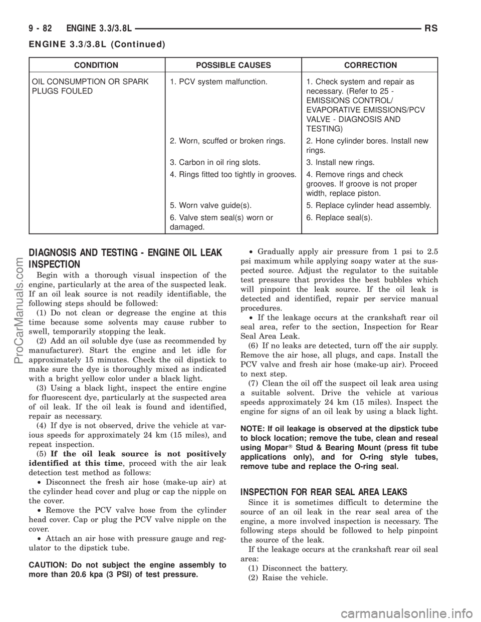
CONDITION POSSIBLE CAUSES CORRECTION
OIL CONSUMPTION OR SPARK
PLUGS FOULED1. PCV system malfunction. 1. Check system and repair as
necessary. (Refer to 25 -
EMISSIONS CONTROL/
EVAPORATIVE EMISSIONS/PCV
VALVE - DIAGNOSIS AND
TESTING)
2. Worn, scuffed or broken rings. 2. Hone cylinder bores. Install new
rings.
3. Carbon in oil ring slots. 3. Install new rings.
4. Rings fitted too tightly in grooves. 4. Remove rings and check
grooves. If groove is not proper
width, replace piston.
5. Worn valve guide(s). 5. Replace cylinder head assembly.
6. Valve stem seal(s) worn or
damaged.6. Replace seal(s).
DIAGNOSIS AND TESTING - ENGINE OIL LEAK
INSPECTION
Begin with a thorough visual inspection of the
engine, particularly at the area of the suspected leak.
If an oil leak source is not readily identifiable, the
following steps should be followed:
(1) Do not clean or degrease the engine at this
time because some solvents may cause rubber to
swell, temporarily stopping the leak.
(2) Add an oil soluble dye (use as recommended by
manufacturer). Start the engine and let idle for
approximately 15 minutes. Check the oil dipstick to
make sure the dye is thoroughly mixed as indicated
with a bright yellow color under a black light.
(3) Using a black light, inspect the entire engine
for fluorescent dye, particularly at the suspected area
of oil leak. If the oil leak is found and identified,
repair as necessary.
(4) If dye is not observed, drive the vehicle at var-
ious speeds for approximately 24 km (15 miles), and
repeat inspection.
(5)If the oil leak source is not positively
identified at this time, proceed with the air leak
detection test method as follows:
²Disconnect the fresh air hose (make-up air) at
the cylinder head cover and plug or cap the nipple on
the cover.
²Remove the PCV valve hose from the cylinder
head cover. Cap or plug the PCV valve nipple on the
cover.
²Attach an air hose with pressure gauge and reg-
ulator to the dipstick tube.
CAUTION: Do not subject the engine assembly to
more than 20.6 kpa (3 PSI) of test pressure.²Gradually apply air pressure from 1 psi to 2.5
psi maximum while applying soapy water at the sus-
pected source. Adjust the regulator to the suitable
test pressure that provides the best bubbles which
will pinpoint the leak source. If the oil leak is
detected and identified, repair per service manual
procedures.
²If the leakage occurs at the crankshaft rear oil
seal area, refer to the section, Inspection for Rear
Seal Area Leak.
(6) If no leaks are detected, turn off the air supply.
Remove the air hose, all plugs, and caps. Install the
PCV valve and fresh air hose (make-up air). Proceed
to next step.
(7) Clean the oil off the suspect oil leak area using
a suitable solvent. Drive the vehicle at various
speeds approximately 24 km (15 miles). Inspect the
engine for signs of an oil leak by using a black light.
NOTE: If oil leakage is observed at the dipstick tube
to block location; remove the tube, clean and reseal
using MoparTStud & Bearing Mount (press fit tube
applications only), and for O-ring style tubes,
remove tube and replace the O-ring seal.
INSPECTION FOR REAR SEAL AREA LEAKS
Since it is sometimes difficult to determine the
source of an oil leak in the rear seal area of the
engine, a more involved inspection is necessary. The
following steps should be followed to help pinpoint
the source of the leak.
If the leakage occurs at the crankshaft rear oil seal
area:
(1) Disconnect the battery.
(2) Raise the vehicle.
9 - 82 ENGINE 3.3/3.8LRS
ENGINE 3.3/3.8L (Continued)
ProCarManuals.com