2002 CHRYSLER CARAVAN height
[x] Cancel search: heightPage 1219 of 2399
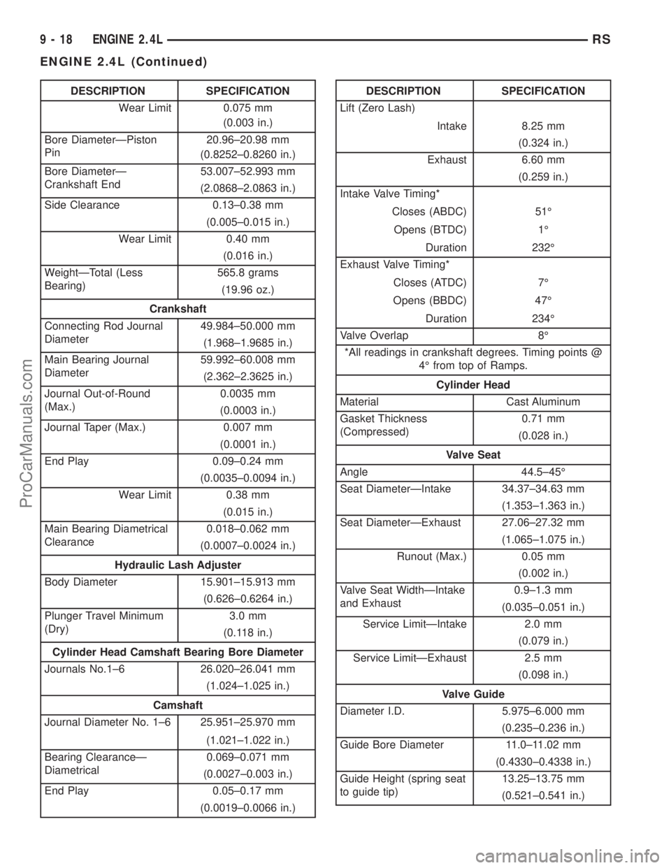
DESCRIPTION SPECIFICATION
Wear Limit 0.075 mm
(0.003 in.)
Bore DiameterÐPiston
Pin20.96±20.98 mm
(0.8252±0.8260 in.)
Bore DiameterÐ
Crankshaft End53.007±52.993 mm
(2.0868±2.0863 in.)
Side Clearance 0.13±0.38 mm
(0.005±0.015 in.)
Wear Limit 0.40 mm
(0.016 in.)
WeightÐTotal (Less
Bearing)565.8 grams
(19.96 oz.)
Crankshaft
Connecting Rod Journal
Diameter49.984±50.000 mm
(1.968±1.9685 in.)
Main Bearing Journal
Diameter59.992±60.008 mm
(2.362±2.3625 in.)
Journal Out-of-Round
(Max.)0.0035 mm
(0.0003 in.)
Journal Taper (Max.) 0.007 mm
(0.0001 in.)
End Play 0.09±0.24 mm
(0.0035±0.0094 in.)
Wear Limit 0.38 mm
(0.015 in.)
Main Bearing Diametrical
Clearance0.018±0.062 mm
(0.0007±0.0024 in.)
Hydraulic Lash Adjuster
Body Diameter 15.901±15.913 mm
(0.626±0.6264 in.)
Plunger Travel Minimum
(Dry)3.0 mm
(0.118 in.)
Cylinder Head Camshaft Bearing Bore Diameter
Journals No.1±6 26.020±26.041 mm
(1.024±1.025 in.)
Camshaft
Journal Diameter No. 1±6 25.951±25.970 mm
(1.021±1.022 in.)
Bearing ClearanceÐ
Diametrical0.069±0.071 mm
(0.0027±0.003 in.)
End Play 0.05±0.17 mm
(0.0019±0.0066 in.)DESCRIPTION SPECIFICATION
Lift (Zero Lash)
Intake 8.25 mm
(0.324 in.)
Exhaust 6.60 mm
(0.259 in.)
Intake Valve Timing*
Closes (ABDC) 51É
Opens (BTDC) 1É
Duration 232É
Exhaust Valve Timing*
Closes (ATDC) 7É
Opens (BBDC) 47É
Duration 234É
Valve Overlap 8É
*All readings in crankshaft degrees. Timing points @
4É from top of Ramps.
Cylinder Head
Material Cast Aluminum
Gasket Thickness
(Compressed)0.71 mm
(0.028 in.)
Valve Seat
Angle 44.5±45É
Seat DiameterÐIntake 34.37±34.63 mm
(1.353±1.363 in.)
Seat DiameterÐExhaust 27.06±27.32 mm
(1.065±1.075 in.)
Runout (Max.) 0.05 mm
(0.002 in.)
Valve Seat WidthÐIntake
and Exhaust0.9±1.3 mm
(0.035±0.051 in.)
Service LimitÐIntake 2.0 mm
(0.079 in.)
Service LimitÐExhaust 2.5 mm
(0.098 in.)
Valve Guide
Diameter I.D. 5.975±6.000 mm
(0.235±0.236 in.)
Guide Bore Diameter 11.0±11.02 mm
(0.4330±0.4338 in.)
Guide Height (spring seat
to guide tip)13.25±13.75 mm
(0.521±0.541 in.)
9 - 18 ENGINE 2.4LRS
ENGINE 2.4L (Continued)
ProCarManuals.com
Page 1220 of 2399
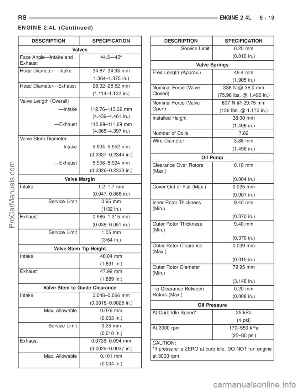
DESCRIPTION SPECIFICATION
Valves
Face AngleÐIntake and
Exhaust44.5Ð45É
Head DiameterÐIntake 34.67±34.93 mm
1.364±1.375 in.)
Head DiameterÐExhaust 28.32±28.52 mm
(1.114±1.122 in.)
Valve Length (Overall)
ÐIntake 112.76±113.32 mm
(4.439±4.461 in.)
ÐExhaust 110.89±111.69 mm
(4.365±4.397 in.)
Valve Stem Diameter
ÐIntake 5.934±5.952 mm
(0.2337±0.2344 in.)
ÐExhaust 5.906±5.924 mm
(0.2326±0.2333 in.)
Valve Margin
Intake 1.2±1.7 mm
(0.047±0.066 in.)
Service Limit 0.95 mm
(1/32 in.)
Exhaust 0.985±1.315 mm
(0.038±0.051 in.)
Service Limit 1.05 mm
(3/64 in.)
Valve Stem Tip Height
Intake 48.04 mm
(1.891 in.)
Exhaust 47.99 mm
(1.889 in.)
Valve Stem to Guide Clearance
Intake 0.048±0.066 mm
(0.0018±0.0025 in.)
Max. Allowable 0.076 mm
(0.003 in.)
Service Limit 0.25 mm
(0.010 in.)
Exhaust 0.0736±0.094 mm
(0.0029±0.0037 in.)
Max. Allowable 0.101 mm
(0.004 in.)DESCRIPTION SPECIFICATION
Service Limit 0.25 mm
(0.010 in.)
Valve Springs
Free Length (Approx.) 48.4 mm
(1.905 in.)
Nominal Force (Valve
Closed)338 N @ 38.0 mm
(75.98 lbs. @ 1.496 in.)
Nominal Force (Valve
Open)607 N @ 29.75 mm
(136 lbs. @ 1.172 in.)
Installed Height 38.00 mm
(1.496 in.)
Number of Coils 7.82
Wire Diameter 3.86 mm
(1.496 in.)
Oil Pump
Clearance Over Rotors
(Max.)0.10 mm
(0.004 in.)
Cover Out-of-Flat (Max.) 0.025 mm
(0.001 in.)
Inner Rotor Thickness
(Min.)9.40 mm
(0.370 in.)
Outer Rotor Thickness
(Min.)9.40 mm
(0.370 in.)
Outer Rotor Clearance
(Max.)0.039 mm
(0.015 in.)
Outer Rotor Diameter
(Min.)79.95 mm
(3.148 in.)
Tip Clearance Between
Rotors (Max.)0.20 mm
(0.008 in.)
Oil Pressure
At Curb Idle Speed* 25 kPa
(4 psi)
At 3000 rpm 170±550 kPa
(25±80 psi)
CAUTION:
*If pressure is ZERO at curb idle, DO NOT run engine
at 3000 rpm.
RSENGINE 2.4L9-19
ENGINE 2.4L (Continued)
ProCarManuals.com
Page 1227 of 2399
(13) Remove timing belt and camshaft sprockets.
(Refer to 9 - ENGINE/VALVE TIMING/TIMING
BELT/CHAIN AND SPROCKETS - REMOVAL)
(14) Remove timing belt idler pulley and rear tim-
ing belt cover. (Refer to 9 - ENGINE/VALVE TIM-
ING/TIMING BELT / CHAIN COVER(S) -
REMOVAL)
(15) Remove cylinder head cover. (Refer to 9 -
ENGINE/CYLINDER HEAD/CYLINDER HEAD
COVER(S) - REMOVAL)
(16) Remove camshafts (Refer to 9 - ENGINE/
CYLINDER HEAD/CAMSHAFT(S) - REMOVAL).
NOTE: Identify rocker arm position to ensure cor-
rect re-installation in original position, if reused.
(17) Remove rocker arms. (Refer to 9 - ENGINE/
CYLINDER HEAD/ROCKER ARMS - REMOVAL)
(18) Remove cylinder head bolts in REVERSE
sequence of tightening (Fig. 19).
(19) Remove cylinder head from engine block.
(20) Inspect and clean cylinder head. (Refer to 9 -
ENGINE/CYLINDER HEAD - INSPECTION) (Refer
to 9 - ENGINE/CYLINDER HEAD - CLEANING)
CLEANING
To ensure engine gasket sealing, proper surface
preparation must be performed, especially with the
use of aluminum engine components and multi-layer
steel cylinder head gaskets.
NOTE: Multi-Layer Steel (MLS) head gaskets require
a scratch free sealing surface.
Remove all gasket material from cylinder head and
block (Refer to 9 - ENGINE - STANDARD PROCE-
DURE). Be careful not to gouge or scratch the alumi-
num head sealing surface.
Clean all engine oil passages.
INSPECTION
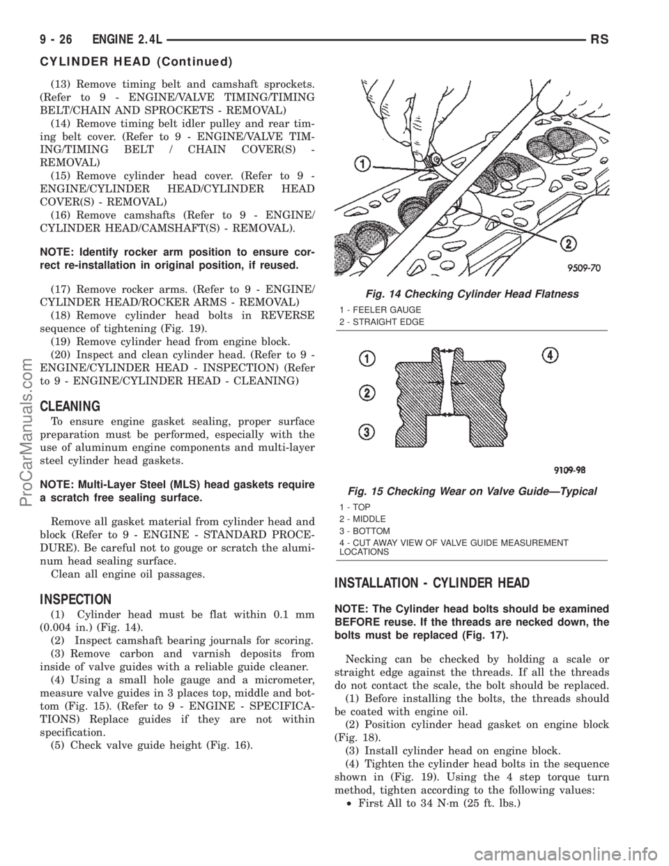
(1) Cylinder head must be flat within 0.1 mm
(0.004 in.) (Fig. 14).
(2) Inspect camshaft bearing journals for scoring.
(3) Remove carbon and varnish deposits from
inside of valve guides with a reliable guide cleaner.
(4) Using a small hole gauge and a micrometer,
measure valve guides in 3 places top, middle and bot-
tom (Fig. 15). (Refer to 9 - ENGINE - SPECIFICA-
TIONS) Replace guides if they are not within
specification.
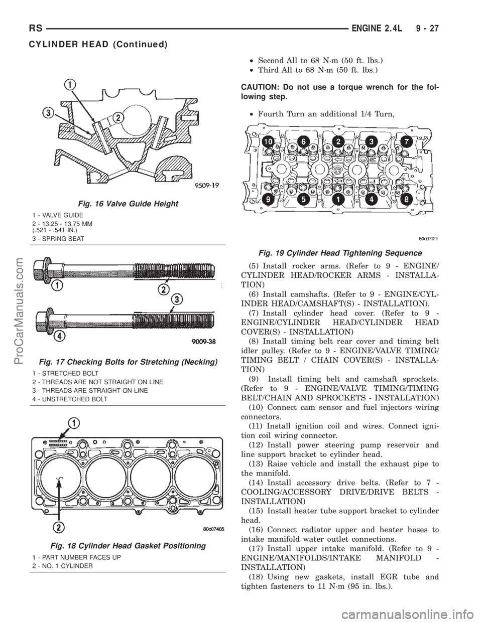
(5) Check valve guide height (Fig. 16).
INSTALLATION - CYLINDER HEAD
NOTE: The Cylinder head bolts should be examined
BEFORE reuse. If the threads are necked down, the
bolts must be replaced (Fig. 17).
Necking can be checked by holding a scale or
straight edge against the threads. If all the threads
do not contact the scale, the bolt should be replaced.
(1) Before installing the bolts, the threads should
be coated with engine oil.
(2) Position cylinder head gasket on engine block
(Fig. 18).
(3) Install cylinder head on engine block.
(4) Tighten the cylinder head bolts in the sequence
shown in (Fig. 19). Using the 4 step torque turn
method, tighten according to the following values:
²First All to 34 N´m (25 ft. lbs.)
Fig. 14 Checking Cylinder Head Flatness
1 - FEELER GAUGE
2 - STRAIGHT EDGE
Fig. 15 Checking Wear on Valve GuideÐTypical
1-TOP
2 - MIDDLE
3 - BOTTOM
4 - CUT AWAY VIEW OF VALVE GUIDE MEASUREMENT
LOCATIONS
9 - 26 ENGINE 2.4LRS
CYLINDER HEAD (Continued)
ProCarManuals.com
Page 1228 of 2399
²Second All to 68 N´m (50 ft. lbs.)
²Third All to 68 N´m (50 ft. lbs.)
CAUTION: Do not use a torque wrench for the fol-
lowing step.
²Fourth Turn an additional 1/4 Turn,
(5) Install rocker arms. (Refer to 9 - ENGINE/
CYLINDER HEAD/ROCKER ARMS - INSTALLA-
TION)
(6) Install camshafts. (Refer to 9 - ENGINE/CYL-
INDER HEAD/CAMSHAFT(S) - INSTALLATION).
(7) Install cylinder head cover. (Refer to 9 -
ENGINE/CYLINDER HEAD/CYLINDER HEAD
COVER(S) - INSTALLATION)
(8) Install timing belt rear cover and timing belt
idler pulley. (Refer to 9 - ENGINE/VALVE TIMING/
TIMING BELT / CHAIN COVER(S) - INSTALLA-
TION)
(9) Install timing belt and camshaft sprockets.
(Refer to 9 - ENGINE/VALVE TIMING/TIMING
BELT/CHAIN AND SPROCKETS - INSTALLATION)
(10) Connect cam sensor and fuel injectors wiring
connectors.
(11) Install ignition coil and wires. Connect igni-
tion coil wiring connector.
(12) Install power steering pump reservoir and
line support bracket to cylinder head.
(13) Raise vehicle and install the exhaust pipe to
the manifold.
(14) Install accessory drive belts. (Refer to 7 -
COOLING/ACCESSORY DRIVE/DRIVE BELTS -
INSTALLATION)
(15) Install heater tube support bracket to cylinder
head.
(16) Connect radiator upper and heater hoses to
intake manifold water outlet connections.
(17) Install upper intake manifold. (Refer to 9 -
ENGINE/MANIFOLDS/INTAKE MANIFOLD -
INSTALLATION)
(18) Using new gaskets, install EGR tube and
tighten fasteners to 11 N´m (95 in. lbs.).
Fig. 16 Valve Guide Height
1 - VALVE GUIDE
2 - 13.25 - 13.75 MM
(.521 - .541 IN.)
3 - SPRING SEAT
Fig. 17 Checking Bolts for Stretching (Necking)
1 - STRETCHED BOLT
2 - THREADS ARE NOT STRAIGHT ON LINE
3 - THREADS ARE STRAIGHT ON LINE
4 - UNSTRETCHED BOLT
Fig. 18 Cylinder Head Gasket Positioning
1 - PART NUMBER FACES UP
2 - NO. 1 CYLINDER
Fig. 19 Cylinder Head Tightening Sequence
RSENGINE 2.4L9-27
CYLINDER HEAD (Continued)
ProCarManuals.com
Page 1235 of 2399
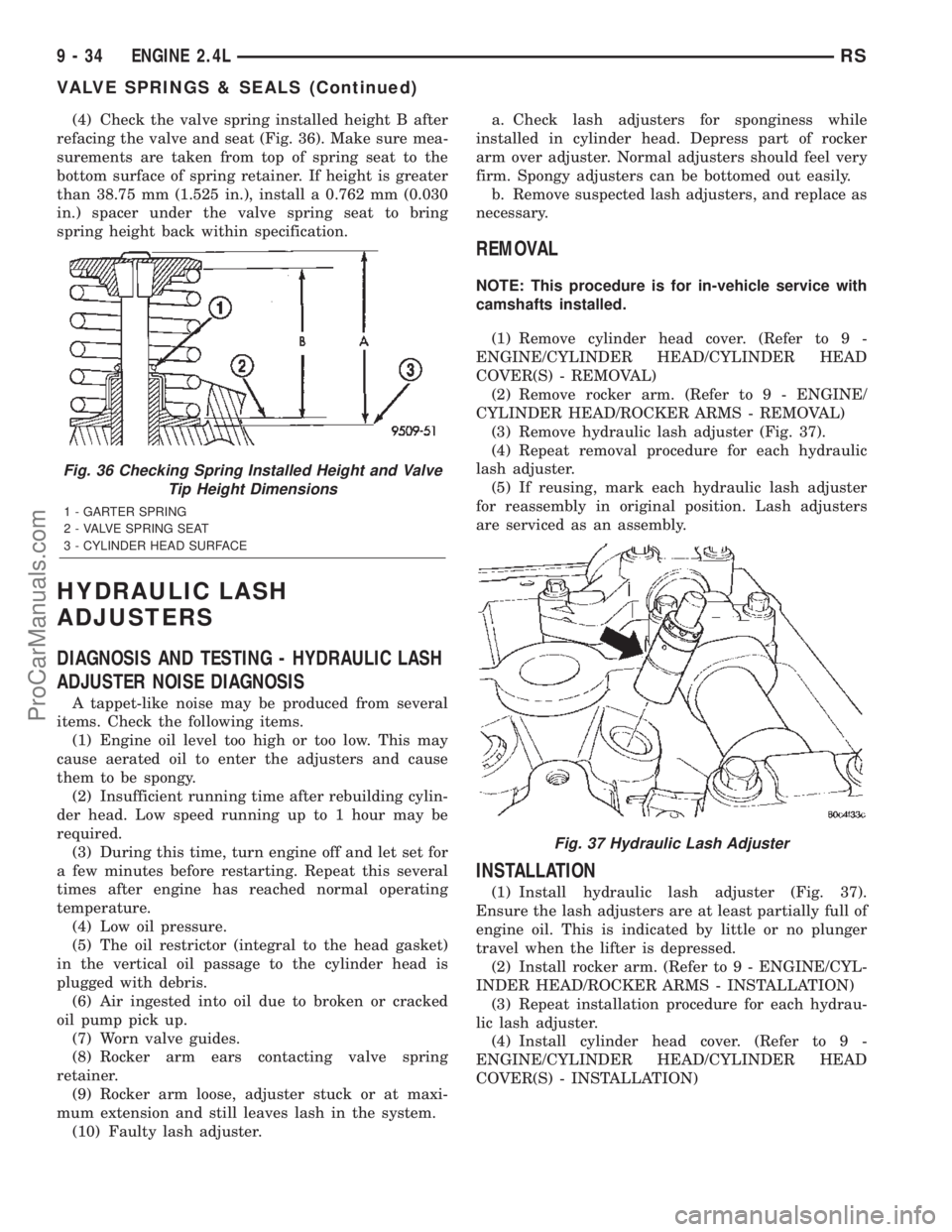
(4) Check the valve spring installed height B after
refacing the valve and seat (Fig. 36). Make sure mea-
surements are taken from top of spring seat to the
bottom surface of spring retainer. If height is greater
than 38.75 mm (1.525 in.), install a 0.762 mm (0.030
in.) spacer under the valve spring seat to bring
spring height back within specification.
HYDRAULIC LASH
ADJUSTERS
DIAGNOSIS AND TESTING - HYDRAULIC LASH
ADJUSTER NOISE DIAGNOSIS
A tappet-like noise may be produced from several
items. Check the following items.
(1) Engine oil level too high or too low. This may
cause aerated oil to enter the adjusters and cause
them to be spongy.
(2) Insufficient running time after rebuilding cylin-
der head. Low speed running up to 1 hour may be
required.
(3) During this time, turn engine off and let set for
a few minutes before restarting. Repeat this several
times after engine has reached normal operating
temperature.
(4) Low oil pressure.
(5) The oil restrictor (integral to the head gasket)
in the vertical oil passage to the cylinder head is
plugged with debris.
(6) Air ingested into oil due to broken or cracked
oil pump pick up.
(7) Worn valve guides.
(8) Rocker arm ears contacting valve spring
retainer.
(9) Rocker arm loose, adjuster stuck or at maxi-
mum extension and still leaves lash in the system.
(10) Faulty lash adjuster.a. Check lash adjusters for sponginess while
installed in cylinder head. Depress part of rocker
arm over adjuster. Normal adjusters should feel very
firm. Spongy adjusters can be bottomed out easily.
b. Remove suspected lash adjusters, and replace as
necessary.
REMOVAL
NOTE: This procedure is for in-vehicle service with
camshafts installed.
(1) Remove cylinder head cover. (Refer to 9 -
ENGINE/CYLINDER HEAD/CYLINDER HEAD
COVER(S) - REMOVAL)
(2) Remove rocker arm. (Refer to 9 - ENGINE/
CYLINDER HEAD/ROCKER ARMS - REMOVAL)
(3) Remove hydraulic lash adjuster (Fig. 37).
(4) Repeat removal procedure for each hydraulic
lash adjuster.
(5) If reusing, mark each hydraulic lash adjuster
for reassembly in original position. Lash adjusters
are serviced as an assembly.
INSTALLATION
(1) Install hydraulic lash adjuster (Fig. 37).
Ensure the lash adjusters are at least partially full of
engine oil. This is indicated by little or no plunger
travel when the lifter is depressed.
(2) Install rocker arm. (Refer to 9 - ENGINE/CYL-
INDER HEAD/ROCKER ARMS - INSTALLATION)
(3) Repeat installation procedure for each hydrau-
lic lash adjuster.
(4) Install cylinder head cover. (Refer to 9 -
ENGINE/CYLINDER HEAD/CYLINDER HEAD
COVER(S) - INSTALLATION)
Fig. 36 Checking Spring Installed Height and Valve
Tip Height Dimensions
1 - GARTER SPRING
2 - VALVE SPRING SEAT
3 - CYLINDER HEAD SURFACE
Fig. 37 Hydraulic Lash Adjuster
9 - 34 ENGINE 2.4LRS
VALVE SPRINGS & SEALS (Continued)
ProCarManuals.com
Page 1295 of 2399
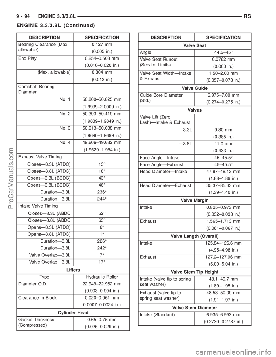
DESCRIPTION SPECIFICATION
Bearing Clearance (Max.
allowable)0.127 mm
(0.005 in.)
End Play 0.254±0.508 mm
(0.010±0.020 in.)
(Max. allowable) 0.304 mm
(0.012 in.)
Camshaft Bearing
Diameter
No. 1 50.800±50.825 mm
(1.9999±2.0009 in.)
No. 2 50.393±50.419 mm
(1.9839±1.9849 in.)
No. 3 50.013±50.038 mm
(1.9690±1.9699 in.)
No. 4 49.606±49.632 mm
(1.9529±1.954 in.)
Exhaust Valve Timing
ClosesÐ3.3L (ATDC) 13É
ClosesÐ3.8L (ATDC) 18É
OpensÐ3.3L (BBDC) 43É
OpensÐ3.8L (BBDC) 46É
DurationÐ3.3L 236É
DurationÐ3.8L 244É
Intake Valve Timing
ClosesÐ3.3L (ABDC 52É
ClosesÐ3.8L (ABDC 63É
OpensÐ3.3L (ATDC) 6É
OpensÐ3.8L (ATDC) 1É
DurationÐ3.3L 226É
DurationÐ3.8L 242É
Valve OverlapÐ3.3L 7É
Valve OverlapÐ3.8L 17É
Lifters
Type Hydraulic Roller
Diameter O.D. 22.949±22.962 mm
(0.903±0.904 in.)
Clearance In Block 0.020±0.061 mm
0.0007±0.0024 in.)
Cylinder Head
Gasket Thickness
(Compressed)0.65±0.75 mm
(0.025±0.029 in.)DESCRIPTION SPECIFICATION
Valve Seat
Angle 44.5±45É
Valve Seat Runout
(Service Limits)0.0762 mm
(0.003 in.)
Valve Seat WidthÐIntake
& Exhaust1.50±2.00 mm
(0.057±0.078 in.)
Valve Guide
Guide Bore Diameter
(Std.)6.975±7.00 mm
(0.274±0.275 in.)
Valves
Valve Lift (Zero
Lash)ÐIntake & Exhaust
Ð3.3L 9.80 mm
(0.385 in.)
Ð3.8L 11.0 mm
(0.433 in.)
Face AngleÐIntake 45±45.5É
Face AngleÐExhaust 45±45.5É
Head DiameterÐIntake 47.87±48.13 mm
(1.88±1.89 in.)
Head DiameterÐExhaust 35.37±35.63 mm
(1.39±1.40 in.)
Valve Margin
Intake 0.825±0.973 mm
(0.032±0.038 in.)
Exhaust 1.565±1.713 mm
(0.061±0.067 in.)
Valve Length (Overall)
Intake 125.84±126.6 mm
(4.95±4.98 in.)
Exhaust 127.2±127.96 mm
(5.00±5.04 in.)
Valve Stem Tip Height
Intake (valve tip to spring
seat washer)48.1±49.7 mm
(1.89±1.95 in.)
Exhaust (valve tip to
spring seat washer)48.53±50.09 mm
(1.91±1.97 in.)
Valve Stem Diameter
Intake (Standard) 6.935±6.953 mm
(0.2730±0.2737 in.)
9 - 94 ENGINE 3.3/3.8LRS
ENGINE 3.3/3.8L (Continued)
ProCarManuals.com
Page 1296 of 2399
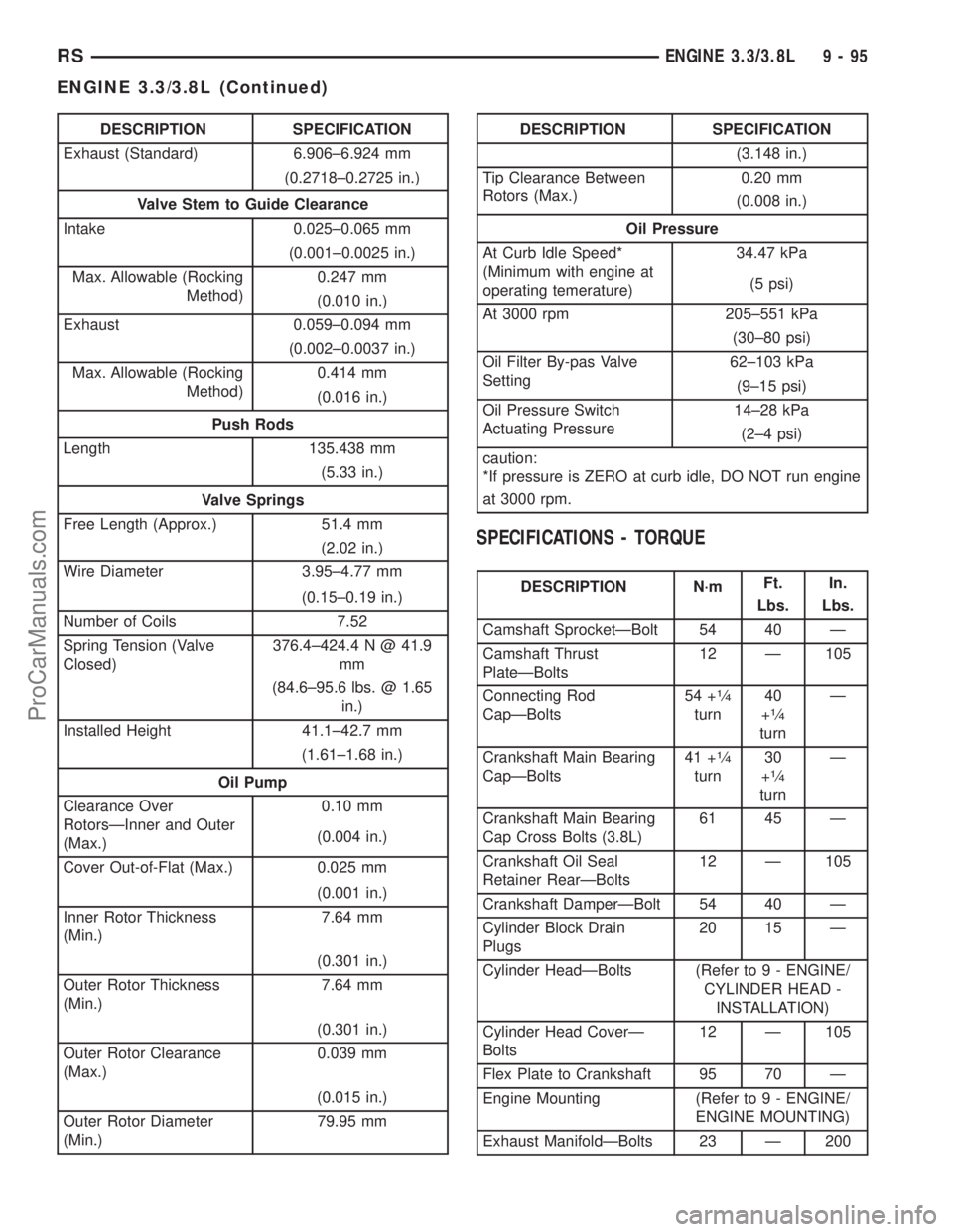
DESCRIPTION SPECIFICATION
Exhaust (Standard) 6.906±6.924 mm
(0.2718±0.2725 in.)
Valve Stem to Guide Clearance
Intake 0.025±0.065 mm
(0.001±0.0025 in.)
Max. Allowable (Rocking
Method)0.247 mm
(0.010 in.)
Exhaust 0.059±0.094 mm
(0.002±0.0037 in.)
Max. Allowable (Rocking
Method)0.414 mm
(0.016 in.)
Push Rods
Length 135.438 mm
(5.33 in.)
Valve Springs
Free Length (Approx.) 51.4 mm
(2.02 in.)
Wire Diameter 3.95±4.77 mm
(0.15±0.19 in.)
Number of Coils 7.52
Spring Tension (Valve
Closed)376.4±424.4 N @ 41.9
mm
(84.6±95.6 lbs. @ 1.65
in.)
Installed Height 41.1±42.7 mm
(1.61±1.68 in.)
Oil Pump
Clearance Over
RotorsÐInner and Outer
(Max.)0.10 mm
(0.004 in.)
Cover Out-of-Flat (Max.) 0.025 mm
(0.001 in.)
Inner Rotor Thickness
(Min.)7.64 mm
(0.301 in.)
Outer Rotor Thickness
(Min.)7.64 mm
(0.301 in.)
Outer Rotor Clearance
(Max.)0.039 mm
(0.015 in.)
Outer Rotor Diameter
(Min.)79.95 mmDESCRIPTION SPECIFICATION
(3.148 in.)
Tip Clearance Between
Rotors (Max.)0.20 mm
(0.008 in.)
Oil Pressure
At Curb Idle Speed*
(Minimum with engine at
operating temerature)34.47 kPa
(5 psi)
At 3000 rpm 205±551 kPa
(30±80 psi)
Oil Filter By-pas Valve
Setting62±103 kPa
(9±15 psi)
Oil Pressure Switch
Actuating Pressure14±28 kPa
(2±4 psi)
caution:
*If pressure is ZERO at curb idle, DO NOT run engine
at 3000 rpm.
SPECIFICATIONS - TORQUE
DESCRIPTION N´mFt.
Lbs.In.
Lbs.
Camshaft SprocketÐBolt 54 40 Ð
Camshaft Thrust
PlateÐBolts12 Ð 105
Connecting Rod
CapÐBolts54 +
1¤4
turn40
+1¤4
turnÐ
Crankshaft Main Bearing
CapÐBolts41 +
1¤4
turn30
+1¤4
turnÐ
Crankshaft Main Bearing
Cap Cross Bolts (3.8L)61 45 Ð
Crankshaft Oil Seal
Retainer RearÐBolts12 Ð 105
Crankshaft DamperÐBolt 54 40 Ð
Cylinder Block Drain
Plugs20 15 Ð
Cylinder HeadÐBolts (Refer to 9 - ENGINE/
CYLINDER HEAD -
INSTALLATION)
Cylinder Head CoverÐ
Bolts12 Ð 105
Flex Plate to Crankshaft 95 70 Ð
Engine Mounting (Refer to 9 - ENGINE/
ENGINE MOUNTING)
Exhaust ManifoldÐBolts 23 Ð 200
RSENGINE 3.3/3.8L9-95
ENGINE 3.3/3.8L (Continued)
ProCarManuals.com
Page 1307 of 2399
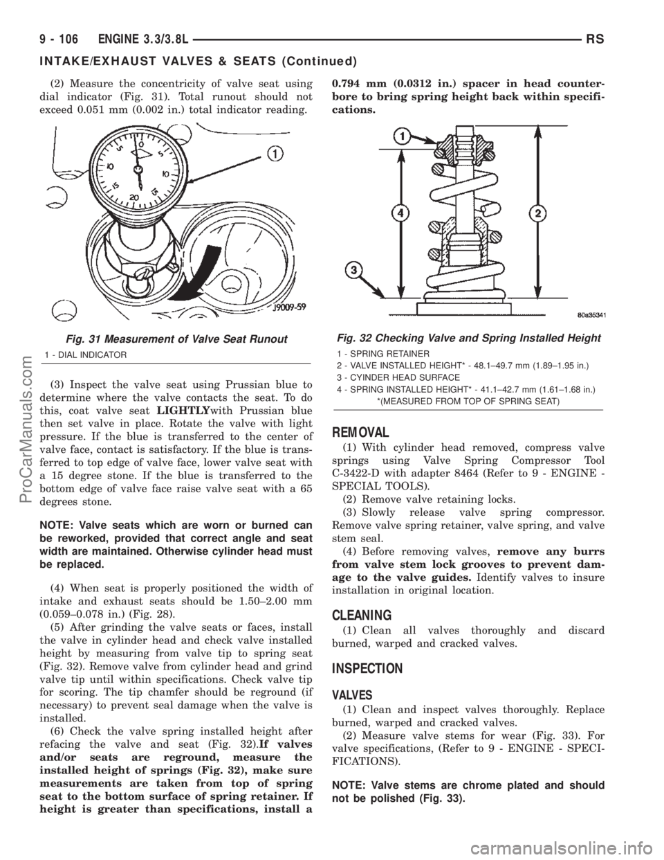
(2) Measure the concentricity of valve seat using
dial indicator (Fig. 31). Total runout should not
exceed 0.051 mm (0.002 in.) total indicator reading.
(3) Inspect the valve seat using Prussian blue to
determine where the valve contacts the seat. To do
this, coat valve seatLIGHTLYwith Prussian blue
then set valve in place. Rotate the valve with light
pressure. If the blue is transferred to the center of
valve face, contact is satisfactory. If the blue is trans-
ferred to top edge of valve face, lower valve seat with
a 15 degree stone. If the blue is transferred to the
bottom edge of valve face raise valve seat with a 65
degrees stone.
NOTE: Valve seats which are worn or burned can
be reworked, provided that correct angle and seat
width are maintained. Otherwise cylinder head must
be replaced.
(4) When seat is properly positioned the width of
intake and exhaust seats should be 1.50±2.00 mm
(0.059±0.078 in.) (Fig. 28).
(5) After grinding the valve seats or faces, install
the valve in cylinder head and check valve installed
height by measuring from valve tip to spring seat
(Fig. 32). Remove valve from cylinder head and grind
valve tip until within specifications. Check valve tip
for scoring. The tip chamfer should be reground (if
necessary) to prevent seal damage when the valve is
installed.
(6) Check the valve spring installed height after
refacing the valve and seat (Fig. 32).If valves
and/or seats are reground, measure the
installed height of springs (Fig. 32), make sure
measurements are taken from top of spring
seat to the bottom surface of spring retainer. If
height is greater than specifications, install a0.794 mm (0.0312 in.) spacer in head counter-
bore to bring spring height back within specifi-
cations.
REMOVAL
(1) With cylinder head removed, compress valve
springs using Valve Spring Compressor Tool
C-3422-D with adapter 8464 (Refer to 9 - ENGINE -
SPECIAL TOOLS).
(2) Remove valve retaining locks.
(3) Slowly release valve spring compressor.
Remove valve spring retainer, valve spring, and valve
stem seal.
(4) Before removing valves,remove any burrs
from valve stem lock grooves to prevent dam-
age to the valve guides.Identify valves to insure
installation in original location.
CLEANING
(1) Clean all valves thoroughly and discard
burned, warped and cracked valves.
INSPECTION
VALVES
(1) Clean and inspect valves thoroughly. Replace
burned, warped and cracked valves.
(2) Measure valve stems for wear (Fig. 33). For
valve specifications, (Refer to 9 - ENGINE - SPECI-
FICATIONS).
NOTE: Valve stems are chrome plated and should
not be polished (Fig. 33).
Fig. 31 Measurement of Valve Seat Runout
1 - DIAL INDICATOR
Fig. 32 Checking Valve and Spring Installed Height
1 - SPRING RETAINER
2 - VALVE INSTALLED HEIGHT* - 48.1±49.7 mm (1.89±1.95 in.)
3 - CYINDER HEAD SURFACE
4 - SPRING INSTALLED HEIGHT* - 41.1±42.7 mm (1.61±1.68 in.)
*(MEASURED FROM TOP OF SPRING SEAT)
9 - 106 ENGINE 3.3/3.8LRS
INTAKE/EXHAUST VALVES & SEATS (Continued)
ProCarManuals.com