2002 CHRYSLER CARAVAN fuel cap
[x] Cancel search: fuel capPage 1493 of 2399
Refer to the maintenance schedules for the recom-
mended fuel filter replacement intervals.
For draining of water from canister, refer to Fuel
Filter/Water Separator Removal/Installation section.
A Water-In-Fuel (WIF) sensor is part of the fuel fil-
ter cap. Refer to Water-In-Fuel Sensor Description/
Operation.
The fuel heater is installed into the filter/separator
housing above the fuel filter. Refer to Fuel Heater
Description/Operation.
FUEL LINES
DESCRIPTION
DESCRIPTION
All fuel lines up to the fuel injection pump are con-
sidered low-pressure. This includes the fuel lines
from: the fuel tank to the fuel transfer pump, and
the fuel transfer pump to the fuel injection pump.
The fuel return lines and the fuel drain lines are also
considered low-pressure lines. High-pressure lines
are used between the fuel injection pump and the
fuel injectors. Also refer to High-Pressure Fuel Lines
Description/Operation.
DESCRIPTION - HIGH PRESSURE FUEL LINES
The high-pressure fuel lines are the 4 lines located
between the fuel injection pump and the fuel injec-
torsctor tubes. All other fuel lines are considered low-
pressure lines.
OPERATION - HIGH PRESSURE FUEL LINES
CAUTION: The high-pressure fuel lines cannot con-
tact each other or other components. Do not
attempt to weld high-pressure fuel lines or to repair
lines that are damaged. If lines are ever kinked or
bent, they must be replaced. Use only the recom-
mended lines when replacement of high-pressure
fuel line is necessary.
High-pressure fuel lines deliver fuel under
extremely high pressure from the injection pump to
the fuel injectors. The lines expand and contract from
the high-pressure fuel pulses generated during the
injection process. All high-pressure fuel lines are of
the same length and inside diameter. Correct high-
pressure fuel line usage and installation is critical to
smooth engine operation.
WARNING: USE EXTREME CAUTION WHEN
INSPECTING FOR HIGH-PRESSURE FUEL LEAKS.
INSPECT FOR HIGH-PRESSURE FUEL LEAKS WITH
A SHEET OF CARDBOARD. HIGH FUEL INJECTIONPRESSURE CAN CAUSE PERSONAL INJURY IF
CONTACT IS MADE WITH THE SKIN.
DIAGNOSIS AND TESTING - HIGH PRESSURE
FUEL LINES
High-pressure fuel line leaks can cause starting
problems and poor engine performance.
WARNING: DUE TO EXTREME FUEL PRESSURES,
USE EXTREME CAUTION WHEN INSPECTING FOR
HIGH-PRESSURE FUEL LEAKS. DO NOT GET YOUR
HAND NEAR A SUSPECTED LEAK. INSPECT FOR
HIGH-PRESSURE FUEL LEAKS WITH A SHEET OF
CARDBOARD. HIGH FUEL INJECTION PRESSURE
CAN CAUSE PERSONAL INJURY IF CONTACT IS
MADE WITH THE SKIN.
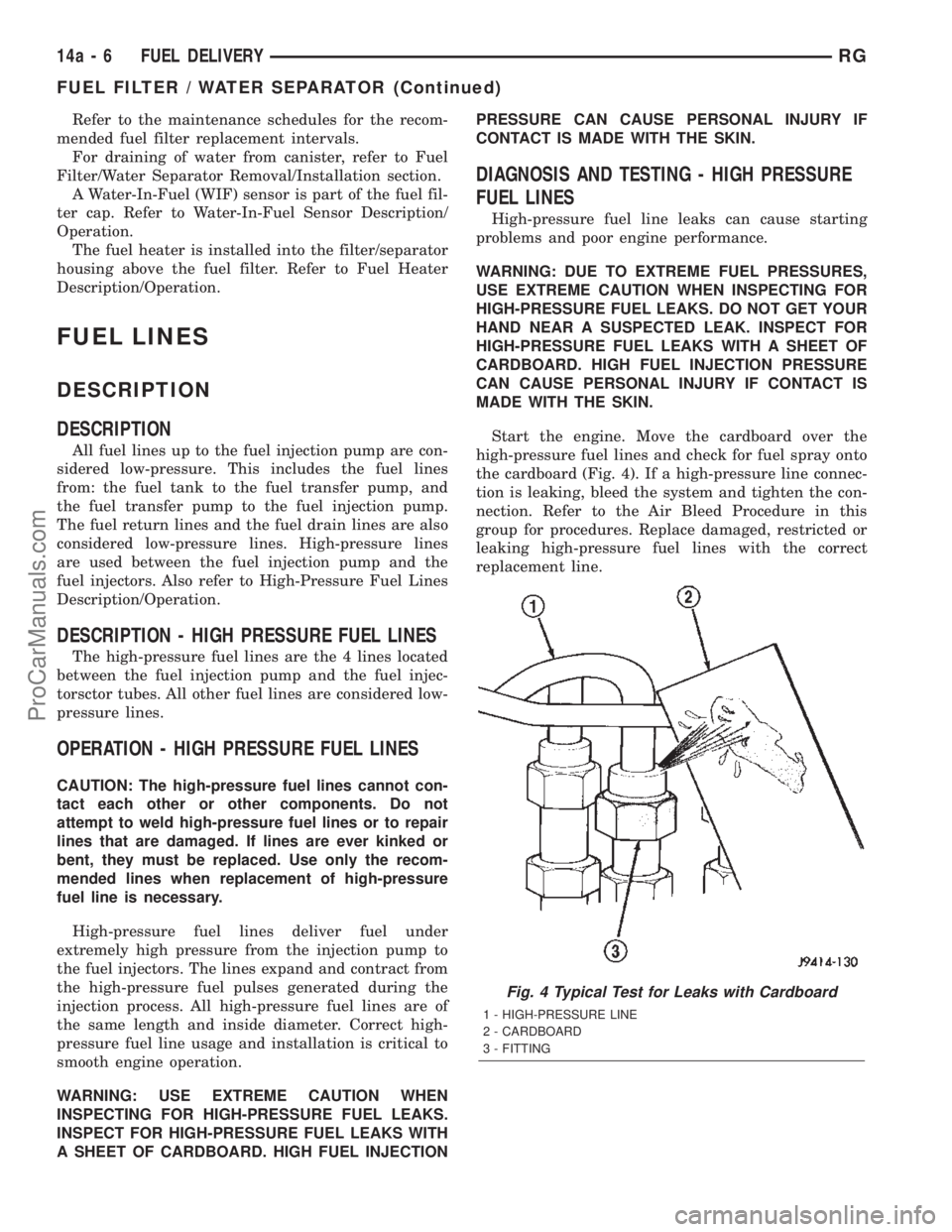
Start the engine. Move the cardboard over the
high-pressure fuel lines and check for fuel spray onto
the cardboard (Fig. 4). If a high-pressure line connec-
tion is leaking, bleed the system and tighten the con-
nection. Refer to the Air Bleed Procedure in this
group for procedures. Replace damaged, restricted or
leaking high-pressure fuel lines with the correct
replacement line.
Fig. 4 Typical Test for Leaks with Cardboard
1 - HIGH-PRESSURE LINE
2 - CARDBOARD
3 - FITTING
14a - 6 FUEL DELIVERYRG
FUEL FILTER / WATER SEPARATOR (Continued)
ProCarManuals.com
Page 1977 of 2399
door temperature drops. After checking the air
pressure, replace valve cap finger tight.
Inflation pressures specified on the Tire Inflation
Pressure Label are always the cold inflation pressure
of the tire. Cold inflation pressure is obtained after
the vehicle has not been operated for at least 3
hours, or the vehicle is driven less than one mile
after being inoperative for 3 hours. Tire inflation
pressures may increase from 2 to 6 pounds persquare inch (psi) (14 to 41 kPa) during operation. Do
not reduce this normal pressure buildup.
Improper inflation can cause:
²Uneven wear patterns
²Reduced tread life
²Reduced fuel economy
²Unsatisfactory ride
²The vehicle to drift.
WARNING: OVER OR UNDER INFLATED TIRES CAN
AFFECT VEHICLE HANDLING. THE TIRE CAN FAIL
SUDDENLY, RESULTING IN LOSS OF VEHICLE
CONTROL.
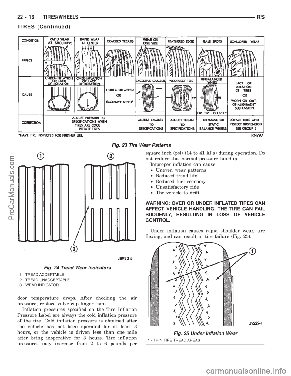
Under inflation causes rapid shoulder wear, tire
flexing, and can result in tire failure (Fig. 25).
Fig. 23 Tire Wear Patterns
Fig. 24 Tread Wear Indicators
1 - TREAD ACCEPTABLE
2 - TREAD UNACCEPTABLE
3 - WEAR INDICATOR
Fig. 25 Under Inflation Wear
1 - THIN TIRE TREAD AREAS
22 - 16 TIRES/WHEELSRS
TIRES (Continued)
ProCarManuals.com
Page 2303 of 2399
PLUMBING - FRONT
WARNING
WARNING
WARNING: DO NOT OPERATE DCHA IN AN
ENCLOSED AREA SUCH AS A GARAGE THAT
DOES NOT HAVE EXHAUST VENTILATION FACILI-
TIES. ALWAYS VENT THE DCHA'S EXHAUST WHEN
OPERATING THE DCHA. FAILURE TO FOLLOW
THESE INSTRUCTION MAY RESULT IN PERSONAL
INJURY OR DEATH.
ALLOW THE DCHA ASSEMBLY TO COOL BEFORE
PERFORMING A COMPONENT INSPECTION/RE-
PAIR/REPLACEMENT. FAILURE TO FOLLOW THESE
INSTRUCTIONS MY RESULT IN PERSONAL INJURY.
VERIFY THAT ALL DCHA FUEL LINES ARE
SECURELY FASTENED TO THEIR RESPECTIVE
COMPONENTS BEFORE THIS PROCEDURE.
WARNING
WARNING:: THE ENGINE COOLING SYSTEM IS
DESIGNED TO DEVELOP INTERNAL PRESSURES
OF 97 TO 123 KILOPASCALS (14 TO 18 POUNDS
PER SQUARE INCH). DO NOT REMOVE OR
LOOSEN THE COOLANT PRESSURE CAP, CYLIN-
DER BLOCK DRAIN PLUGS, RADIATOR DRAIN,
RADIATOR HOSES, HEATER HOSES, OR HOSE
CLAMPS WHILE THE SYSTEM IS HOT AND UNDER
PRESSURE. FAILURE TO OBSERVE THIS WARNING
CAN RESULT IN SERIOUS BURNS FROM THE
HEATED ENGINE COOLANT. ALLOW THE VEHICLE
TO COOL FOR A MINIMUM OF 15 MINUTES
BEFORE OPENING THE COOLING SYSTEM FOR
SERVICE.
WARNING: THE ENGINE COOLING SYSTEM CON-
TAINS ANTIFREEZE. ANTIFREEZE IS AN ETHYLENE
GLYCOL BASED COOLANT AND IS HARMFUL IF
SWALLOWED OR IF THE VAPORS ARE INHALED. IF
SWALLOWED, DRINK TWO GLASSES OF WATER
AND INDUCE VOMITING. IF VAPORS ARE INHALED,
MOVE TO AN AREA FOR FRESH AIR. SEEK MEDI-
CAL ATTENTION IMMEDIATELY. DO NOT STORE IN
OPEN OR UNMARKED CONTAINERS. WASH SKIN
AND CLOTHING THOROUGHLY AFTER COMING IN
CONTACT WITH ETHYLENE GLYCOL. KEEP OUT
OF REACH OF CHILDREN.
WARNING: DISPOSE OF ETHYLENE GLYCOL
BASED COOLANT PROPERLY. CONTACT YOURDEALER OR A LOCAL GOVERNMENT AGENCY FOR
THE LOCATION OF AN APPROVED ETHYLENE GLY-
COL COLLECTION AND/OR RECYCLING CENTER IN
YOUR AREA.
WARNING - A/C PLUMBING
WARNING:: THE AIR CONDITIONING SYSTEM CON-
TAINS REFRIGERANT UNDER HIGH PRESSURE.
SEVERE PERSONAL INJURY MAY RESULT FROM
IMPROPER SERVICE PROCEDURES. REPAIRS
SHOULD ONLY BE PERFORMED BY QUALIFIED
SERVICE PERSONNEL.
WARNING: AVOID BREATHING THE REFRIGERANT
AND REFRIGERANT OIL VAPOR OR MIST. EXPO-
SURE MAY IRRITATE THE EYES, NOSE, AND/OR
THROAT. WEAR EYE PROTECTION WHEN SERVIC-
ING THE AIR CONDITIONING REFRIGERANT SYS-
TEM. SERIOUS EYE INJURY CAN RESULT FROM
DIRECT CONTACT WITH THE REFRIGERANT. IF
EYE CONTACT OCCURS, SEEK MEDICAL ATTEN-
TION IMMEDIATELY.
WARNING: DO NOT EXPOSE THE REFRIGERANT
TO OPEN FLAME. POISONOUS GAS IS CREATED
WHEN REFRIGERANT IS BURNED. AN ELEC-
TRONIC LEAK DETECTOR IS RECOMMENDED.
WARNING: IF ACCIDENTAL SYSTEM DISCHARGE
OCCURS, VENTILATE THE WORK AREA BEFORE
RESUMING SERVICE. LARGE AMOUNTS OF
REFRIGERANT RELEASED IN A CLOSED WORK
AREA WILL DISPLACE THE OXYGEN AND CAUSE
SUFFOCATION.
WARNING: THE EVAPORATION RATE OF R-134a
REFRIGERANT AT AVERAGE TEMPERATURE AND
ALTITUDE IS EXTREMELY HIGH. AS A RESULT,
ANYTHING THAT COMES IN CONTACT WITH THE
REFRIGERANT WILL FREEZE. ALWAYS PROTECT
THE SKIN OR DELICATE OBJECTS FROM DIRECT
CONTACT WITH THE REFRIGERANT.
WARNING: THE R-134a SERVICE EQUIPMENT OR
THE VEHICLE REFRIGERANT SYSTEM SHOULD
NOT BE PRESSURE TESTED OR LEAK TESTED
WITH COMPRESSED AIR. SOME MIXTURES OF AIR
AND R-134a HAVE BEEN SHOWN TO BE COMBUS-
TIBLE AT ELEVATED PRESSURES. THESE MIX-
TURES ARE POTENTIALLY DANGEROUS, AND MAY
RESULT IN FIRE OR EXPLOSION CAUSING INJURY
OR PROPERTY DAMAGE.
24 - 60 PLUMBING - FRONTRS
ProCarManuals.com
Page 2355 of 2399
(4) Connect the electrical connector to the fuel
pump by depressing the integral spring and pushing
the connector towards the dosing pump. Pull the con-
nector towards the heater to verify the installation.
(5) Verify function of the heater.
FUEL LINE
STANDARD PROCEDURE - CLEANING
(1) Remove the cabin heater fuel line(Refer to 24 -
HEATING & AIR CONDITIONING/CABIN HEAT-
ER/FUEL LINE - REMOVAL).
(2) With cabin heater line removed from vehicle
place a shop cloth on the fuel tank end of the fuel
line to catch any residue, then apply a small amount
of air pressure to the other end of the fuel line.
(3) Check to see if air pressure is coming from the
tank end of the line. If pressure is flowing unre-
stricted the line is clean.
(4) If the line shows any signs of being restricted
after air pressure is applied, then the fuel line should
be replaced.
(5) Install the cabin heater line(Refer to 24 -
HEATING & AIR CONDITIONING/CABIN HEAT-
ER/FUEL LINE - INSTALLATION).
(6) Verify function of the heater.
REMOVAL
(1) Elevate vehicle on a lift taking note of the
heater exhaust tube flexible section.
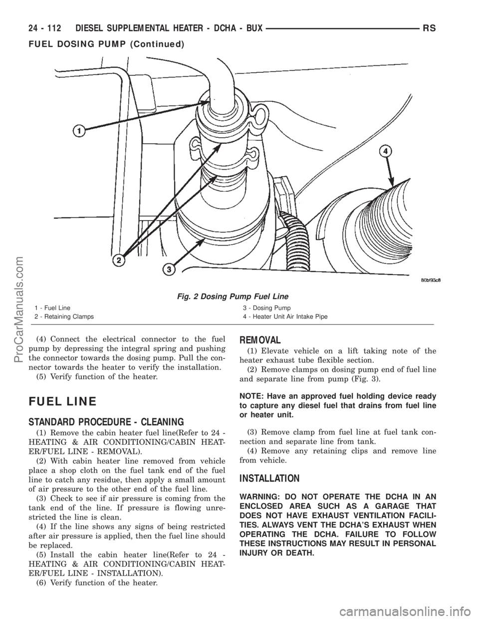
(2) Remove clamps on dosing pump end of fuel line
and separate line from pump (Fig. 3).
NOTE: Have an approved fuel holding device ready
to capture any diesel fuel that drains from fuel line
or heater unit.
(3) Remove clamp from fuel line at fuel tank con-
nection and separate line from tank.
(4) Remove any retaining clips and remove line
from vehicle.
INSTALLATION
WARNING: DO NOT OPERATE THE DCHA IN AN
ENCLOSED AREA SUCH AS A GARAGE THAT
DOES NOT HAVE EXHAUST VENTILATION FACILI-
TIES. ALWAYS VENT THE DCHA'S EXHAUST WHEN
OPERATING THE DCHA. FAILURE TO FOLLOW
THESE INSTRUCTIONS MAY RESULT IN PERSONAL
INJURY OR DEATH.
Fig. 2 Dosing Pump Fuel Line
1 - Fuel Line
2 - Retaining Clamps3 - Dosing Pump
4 - Heater Unit Air Intake Pipe
24 - 112 DIESEL SUPPLEMENTAL HEATER - DCHA - BUXRS
FUEL DOSING PUMP (Continued)
ProCarManuals.com
Page 2357 of 2399
(7) With the DRBIIItin Cabin Heater, select Sys-
tem Tests and Dosing Pump Prime. Allow the Dosing
Pump to run for the full 45 second cycle time. When
the 45 second cycle is complete, press Page Back on
the DRBIIItkey pad to exit the Dosing Pump Prime.
The Dosing Pump priming procedure is now com-
plete.
HEATER UNIT
REMOVAL
WARNING: ALLOW THE DCHA TO COOL BEFORE
PERFORMING A COMPONENT INSPECTION/REPAIR
OR REPLACEMENT. FAILURE TO FOLLOW THESE
INSTRUCTIONS MAY RESULT IN PERSONAL
INJURY.
WARNING: ALLOW THE EXHAUST SYSTEM TO
COOL BEFORE PERFORMING A COMPONENT
INSPECTION/REPAIR OR REPLACEMENT. FAILURE
TO FOLLOW THESE INSTRUCTION MAY RESULT IN
PERSONAL INJURY.
(1) Elevate the vehicle on a hoist/lift taking note of
heater exhaust tube flexible section.
(2) Drain cooling system(Refer to 7 - COOLING -
STANDARD PROCEDURE).
(3) Carefully open one hose to the underbody tube
assembly and drain the remaining coolant. A salvage
hose is a good idea to control the residual coolant, as
flow will occur from both the heater and the hose and
tube assemblies.
(4) Remove the second hose from the underbody
hose and tube assembly.
(5) Loosen the hose and tube assembly from the
toe-board cross member at two locations.
(6) Disconnect the electrical connector from the
body harness near the toe board cross member and
rail.
(7) Remove the wiring harness from the toe board
cross member(Refer to 24 - HEATING & AIR CON-
DITIONING/CABIN HEATER/HEATER UNIT -
REMOVAL).
(8) Open the fuel fill cap. Disconnect the rubber
fuel hose between the body tube assembly and the
fuel pump nipple at the body tube joint. A minimal
amount of fuel may flow from the open port.
NOTE: Utilize an approved fuel storage container to
catch any residual fuel.
(9) Loosen the two M8 fasteners at the rail. Take
care to notice that the exhaust tube bracket tab is on
top of the heater bracket.(10) Remove the heater exhaust tube flex section
from the exhaust tube by loosening the M6 bolt of
the clamp assembly. Remove the hose from the
exhaust tube. Removal of the rail tube assembly may
aid in this service operation.(Refer to 24 - HEATING
& AIR CONDITIONING/CABIN HEATER/EXHAUST
TUBE - REMOVAL).
(11) Remove seat hex nut at the heater mounting
flange to cross member.
(12) Loosen the remaining M6 and M8 fasteners
which mount the exhaust tube assembly to the vehi-
cle.
(a) Install a suitable cabin heater support device
under the cabin heater and secure the cabin heater
to the device.
(13) Loosen the remaining three M6 fasteners to
the cross members.
(14) Remove the loosened fasteners that support
the heater while supporting the weight of the heater.
(15) Swing the unit mounting bracket from
between the exhaust bracket and rail mounting loca-
tion. Drain any residual coolant from the heater unit.
(16) Lower the cabin heater and remove from the
supporting device and place on a suitable work area.
INSTALLATION
(1) Install the unit mounting bracket between the
exhaust bracket and the rail mounting location.
(2) Install the fasteners that support the heater
while supporting the weight of the heater.
(3) Install the three M6 fasteners to the cross
members. Tighten the M6 fasteners to 7 Nm (5 ft.
lbs.).
(4) Tighten the remaining M6 fasteners to 7 Nm (5
ft. lbs.) and the M8 fasteners to 23 Nm (17 ft. lbs.)
which mount the exhaust tube assembly to the vehi-
cle.
(5) Install the seat hex nut at the heater mounting
flange to the cross members. Tighten to 60 Nm (44 ft.
lbs.)
(6) Install the heater exhaust tube flex section to
the exhaust tube by tightening the M6 bolt of the
clamp assembly. Install the hose to the exhaust tube.
(7) Tighten the two M8 fasteners at the rail to 23
Nm (17 ft. lbs.). Taking care so that the exhaust tube
bracket tab is on the top of the heater bracket.
(8) Install the wiring harness(Refer to 24 - HEAT-
ING & AIR CONDITIONING/CABIN HEATER/
HEATER UNIT - INSTALLATION).
(9) Tighten the hose and tube assembly to the toe-
board cross member at two locations.
(10) Install the second hose to the underbody hose
and tube assembly.
(11) Connect the rubber fuel hose between the
body tube assembly and the fuel pump nipple at the
body tube joint. Close the fuel fill cap.
24 - 114 DIESEL SUPPLEMENTAL HEATER - DCHA - BUXRS
FUEL LINE (Continued)
ProCarManuals.com
Page 2363 of 2399
The PCM sends a 5 volt bias to the oxygen sensor
every 1.6 seconds. The PCM keeps it biased for 35
ms each time. As the sensor cools down, the resis-
tance increases and the PCM reads the increase in
voltage. Once voltage has increased to a predeter-
mined amount, higher than when the test started,
the oxygen sensor is cool enough to test heater oper-
ation.
When the oxygen sensor is cool enough, the PCM
energizes the ASD relay. Voltage to the O2 sensor
begins to increase the temperature. As the sensor
temperature increases, the internal resistance
decreases. The PCM continues biasing the 5 volt sig-
nal to the sensor. Each time the signal is biased, the
PCM reads a voltage decrease. When the PCM
detects a voltage decrease of a predetermined value
for several biased pulses, the test passes.
The heater elements are tested each time the
engine is turned OFF if all the enabling conditions
are met. If the monitor fails, the PCM stores a
maturing fault and a Freeze Frame is entered. If two
consecutive tests fail, a DTC is stored. Because the
ignition is OFF, the MIL is illuminated at the begin-
ning of the next key cycle.
Enabling ConditionsÐThe following conditions
must be met for the PCM to run the oxygen sensor
heater test:
²Engine run time of at least 3 minutes
²Engine run time at a predetermind speed and
throttle opening.
²Key OFF power down
²Battery voltage of at least 10 volts
²Sufficient Oxygen Sensor cool down
Pending ConditionsÐThere are not conditions or
situations that prompt conflict or suspension of test-
ing. The oxygen sensor heater test is not run pending
resolution of MIL illumination due to oxygen sensor
failure.
SuspendÐThere are no conditions which exist for
suspending the Heater Monitor.
CATALYST MONITOR
To comply with clean air regulations, vehicles are
equipped with catalytic converters. These converters
reduce the emission of hydrocarbons, oxides of nitro-
gen and carbon monoxide.
Normal vehicle miles or engine misfire can cause a
catalyst to decay. A meltdown of the ceramic core can
cause a reduction of the exhaust passage. This can
increase vehicle emissions and deteriorate engine
performance, driveability and fuel economy.
The catalyst monitor uses dual oxygen sensors
(O2S's) to monitor the efficiency of the converter. The
dual O2S strategy is based on the fact that as a cat-
alyst deteriorates, its oxygen storage capacity and its
efficiency are both reduced. By monitoring the oxy-gen storage capacity of a catalyst, its efficiency can
be indirectly calculated. The upstream O2S is used to
detect the amount of oxygen in the exhaust gas
before the gas enters the catalytic converter. The
PCM calculates the A/F mixture from the output of
the O2S. A low voltage indicates high oxygen content
(lean mixture). A high voltage indicates a low content
of oxygen (rich mixture).
When the upstream O2S detects a lean condition,
there is an abundance of oxygen in the exhaust gas.
A functioning converter would store this oxygen so it
can use it for the oxidation of HC and CO. As the
converter absorbs the oxygen, there will be a lack of
oxygen downstream of the converter. The output of
the downstream O2S will indicate limited activity in
this condition.
As the converter loses the ability to store oxygen,
the condition can be detected from the behavior of
the downstream O2S. When the efficiency drops, no
chemical reaction takes place. This means the con-
centration of oxygen will be the same downstream as
upstream. The output voltage of the downstream
O2S copies the voltage of the upstream sensor. The
only difference is a time lag (seen by the PCM)
between the switching of the O2S's.
To monitor the system, the number of lean-to-rich
switches of upstream and downstream O2S's is
counted. The ratio of downstream switches to
upstream switches is used to determine whether the
catalyst is operating properly. An effective catalyst
will have fewer downstream switches than it has
upstream switches i.e., a ratio closer to zero. For a
totally ineffective catalyst, this ratio will be one-to-
one, indicating that no oxidation occurs in the device.
The system must be monitored so that when cata-
lyst efficiency deteriorates and exhaust emissions
increase to over the legal limit, the MIL (check
engine lamp) will be illuminated.
Monitor OperationÐTo monitor catalyst effi-
ciency, the PCM expands the rich and lean switch
points of the heated oxygen sensor. With extended
switch points, the air/fuel mixture runs richer and
leaner to overburden the catalytic converter. Once
the test is started, the air/fuel mixture runs rich and
lean and the O2 switches are counted. A switch is
counted when an oxygen sensor signal goes from
below the lean threshold to above the rich threshold.
The number of Rear O2 sensor switches is divided by
the number of Front O2 sensor switches to determine
the switching ratio.
The test runs for 20 seconds. As catalyst efficiency
deteriorated over the life of the vehicle, the switch
rate at the downstream sensor approaches that of the
upstream sensor. If at any point during the test
period the switch ratio reaches a predetermined
value, a counter is incremented by one. The monitor
25 - 4 EMISSIONS CONTROLRS
EMISSIONS CONTROL (Continued)
ProCarManuals.com
Page 2366 of 2399
Effective control of exhaust emissions is achieved
by an oxygen feedback system. The most important
element of the feedback system is the O2S. The O2S
is located in the exhaust path. Once it reaches oper-
ating temperatures of 300É to 350ÉC (572 É to 662ÉF),
the sensor generates a voltage that is inversely pro-
portional to the amount of oxygen in the exhaust.
The information obtained by the sensor is used to
calculate the fuel injector pulse width. This main-
tains a 14.7 to 1 Air Fuel (A/F) ratio. At this mixture
ratio, the catalyst works best to remove hydrocarbons
(HC), carbon monoxide (CO) and nitrogen oxide
(NOx) from the exhaust.
The voltage readings taken from the O2S are very
temperature sensitive. The readings are not accurate
below 300ÉC. Heating of the O2S is done to allow the
engine controller to shift to closed loop control as
soon as possible. The heating element used to heat
the O2S must be tested to ensure that it is heating
the sensor properly.
The O2S circuit is monitored for a drop in voltage.
The sensor output is used to test the heater by iso-
lating the effect of the heater element on the O2S
output voltage from the other effects.
EGR MONITOR (if equipped)
The Powertrain Control Module (PCM) performs
an on-board diagnostic check of the EGR system.
The EGR monitor is used to test whether the EGR
system is operating within specifications. The diag-
nostic check activates only during selected engine/
driving conditions. When the conditions are met, the
EGR is turned off (solenoid energized) and the O2S
compensation control is monitored. Turning off the
EGR shifts the air fuel (A/F) ratio in the lean direc-
tion. The O2S data should indicate an increase in the
O2 concentration in the combustion chamber when
the exhaust gases are no longer recirculated. While
this test does not directly measure the operation of
the EGR system, it can be inferred from the shift in
the O2S data whether the EGR system is operating
correctly. Because the O2S is being used, the O2S
test must pass its test before the EGR test. Also
looks at EGR linear potentiometer for feedback.
MISFIRE MONITOR
Excessive engine misfire results in increased cata-
lyst temperature and causes an increase in HC emis-
sions. Severe misfires could cause catalyst damage.
To prevent catalytic convertor damage, the PCM
monitors engine misfire.
The Powertrain Control Module (PCM) monitors
for misfire during most engine operating conditions
(positive torque) by looking at changes in the crank-
shaft speed. If a misfire occurs the speed of the
crankshaft will vary more than normal.FUEL SYSTEM MONITOR
To comply with clean air regulations, vehicles are
equipped with catalytic converters. These converters
reduce the emission of hydrocarbons, oxides of nitro-
gen and carbon monoxide. The catalyst works best
when the air fuel (A/F) ratio is at or near the opti-
mum of 14.7 to 1.
The PCM is programmed to maintain the optimum
air/fuel ratio. This is done by making short term cor-
rections in the fuel injector pulse width based on the
O2S output. The programmed memory acts as a self
calibration tool that the engine controller uses to
compensate for variations in engine specifications,
sensor tolerances and engine fatigue over the life
span of the engine. By monitoring the actual air-fuel
ratio with the O2S (short term) and multiplying that
with the program long-term (adaptive) memory and
comparing that to the limit, it can be determined
whether it will pass an emissions test. If a malfunc-
tion occurs such that the PCM cannot maintain the
optimum A/F ratio, then the MIL will be illuminated.
CATALYST MONITOR
To comply with clean air regulations, vehicles are
equipped with catalytic converters. These converters
reduce the emission of hydrocarbons, oxides of nitro-
gen and carbon monoxide.
Normal vehicle miles or engine misfire can cause a
catalyst to decay. A meltdown of the ceramic core can
cause a reduction of the exhaust passage. This can
increase vehicle emissions and deteriorate engine
performance, driveability and fuel economy.
The catalyst monitor uses dual oxygen sensors
(O2S's) to monitor the efficiency of the converter. The
dual O2S's strategy is based on the fact that as a cat-
alyst deteriorates, its oxygen storage capacity and its
efficiency are both reduced. By monitoring the oxy-
gen storage capacity of a catalyst, its efficiency can
be indirectly calculated. The upstream O2S is used to
detect the amount of oxygen in the exhaust gas
before the gas enters the catalytic converter. The
PCM calculates the A/F mixture from the output of
the O2S. A low voltage indicates high oxygen content
(lean mixture). A high voltage indicates a low content
of oxygen (rich mixture).
When the upstream O2S detects a lean condition,
there is an abundance of oxygen in the exhaust gas.
A functioning converter would store this oxygen so it
can use it for the oxidation of HC and CO. As the
converter absorbs the oxygen, there will be a lack of
oxygen downstream of the converter. The output of
the downstream O2S will indicate limited activity in
this condition.
As the converter loses the ability to store oxygen,
the condition can be detected from the behavior of
the downstream O2S. When the efficiency drops, no
RSEMISSIONS CONTROL25-7
EMISSIONS CONTROL (Continued)
ProCarManuals.com
Page 2367 of 2399
chemical reaction takes place. This means the con-
centration of oxygen will be the same downstream as
upstream. The output voltage of the downstream
O2S copies the voltage of the upstream sensor. The
only difference is a time lag (seen by the PCM)
between the switching of the O2S's.
To monitor the system, the number of lean-to-rich
switches of upstream and downstream O2S's is
counted. The ratio of downstream switches to
upstream switches is used to determine whether the
catalyst is operating properly. An effective catalyst
will have fewer downstream switches than it has
upstream switches i.e., a ratio closer to zero. For a
totally ineffective catalyst, this ratio will be one-to-
one, indicating that no oxidation occurs in the device.
The system must be monitored so that when cata-
lyst efficiency deteriorates and exhaust emissions
increase to over the legal limit, the MIL (Check
Engine lamp) will be illuminated.
LEAK DETECTION PUMP MONITOR (if equipped)
The leak detection assembly incorporates two pri-
mary functions: it must detect a leak in the evapora-
tive system and seal the evaporative system so the
leak detection test can be run.
The primary components within the assembly are:
A three port solenoid that activates both of the func-
tions listed above; a pump which contains a switch,
two check valves, a spring/diaphragm, and a canister
vent valve (CVV) seal which contains a spring loaded
vent seal valve.
Immediately after a cold start, between predeter-
mined temperature thresholds limits, the three port
solenoid is briefly energized. This initializes the
pump by drawing air into the pump cavity and also
closes the vent seal. During non test conditions the
vent seal is held open by the pump diaphragm
assembly which pushes it open at the full travel posi-
tion. The vent seal will remain closed while the
pump is cycling due to the reed switch triggering of
the three port solenoid that prevents the diaphragm
assembly from reaching full travel. After the brief
initialization period, the solenoid is de-energized
allowing atmospheric pressure to enter the pump
cavity, thus permitting the spring to drive the dia-
phragm which forces air out of the pump cavity and
into the vent system. When the solenoid is energized
and de energized, the cycle is repeated creating flow
in typical diaphragm pump fashion. The pump is con-
trolled in 2 modes:
Pump Mode:The pump is cycled at a fixed rate to
achieve a rapid pressure build in order to shorten the
overall test length.
Test Mode:The solenoid is energized with a fixed
duration pulse. Subsequent fixed pulses occur when
the diaphragm reaches the Switch closure point.The spring in the pump is set so that the system
will achieve an equalized pressure of about 7.5º
water. The cycle rate of pump strokes is quite rapid
as the system begins to pump up to this pressure. As
the pressure increases, the cycle rate starts to drop
off. If there is no leak in the system, the pump would
eventually stop pumping at the equalized pressure. If
there is a leak, it will continue to pump at a rate rep-
resentative of the flow characteristic of the size of the
leak. From this information we can determine if the
leak is larger than the required detection limit (cur-
rently set at .020º orifice by CARB). If a leak is
revealed during the leak test portion of the test, the
test is terminated at the end of the test mode and no
further system checks will be performed.
The canister vent valve will unseal the system
after completion of the test sequence as the pump
diaphragm assembly moves to the full travel position.
Evaporative system functionality will be verified by
using the stricter evap purge flow monitor. At an
appropriate warm idle the LDP will be energized to
seal the canister vent. The purge flow will be clocked
up from some small value in an attempt to see a
shift in the 02 control system. If fuel vapor, indicated
by a shift in the 02 control, is present the test is
passed. If not, it is assumed that the purge system is
not functioning in some respect. The LDP is again
turned off and the test is ended.
Natural Vacuum Leak Detection (NVLD) (if equipped)
The Natural Vacuum Leak Detection (NVLD) sys-
tem is the next generation evaporative leak detection
system that will first be used on vehicles equipped
with the Next Generation Controller (NGC) starting
in 2002 M.Y. This new system replaces the leak
detection pump as the method of evaporative system
leak detection. This is to detect a leak equivalent to a
0.0209(0.5 mm) hole. This system has the capability
to detect holes of this size very dependably.
The basic leak detection theory employed with
NVLD is the9Gas Law9. This is to say that the pres-
sure in a sealed vessel will change if the temperature
of the gas in the vessel changes. The vessel will only
see this effect if it is indeed sealed. Even small leaks
will allow the pressure in the vessel to come to equi-
librium with the ambient pressure. In addition to the
detection of very small leaks, this system has the
capability of detecting medium as well as large evap-
orative system leaks.
A vent valve seals the canister vent during engine
off conditions. If the vapor system has a leak of less
than the failure threshold, the evaporative system
will be pulled into a vacuum, either due to the cool
down from operating temperature or diurnal ambient
temperature cycling. The diurnal effect is considered
one of the primary contributors to the leak determi-
25 - 8 EMISSIONS CONTROLRS
EMISSIONS CONTROL (Continued)
ProCarManuals.com