2002 CHRYSLER CARAVAN air conditioning
[x] Cancel search: air conditioningPage 1366 of 2399
(17) Remove battery shield.
(18) Remove charge air cooler outlet hose.
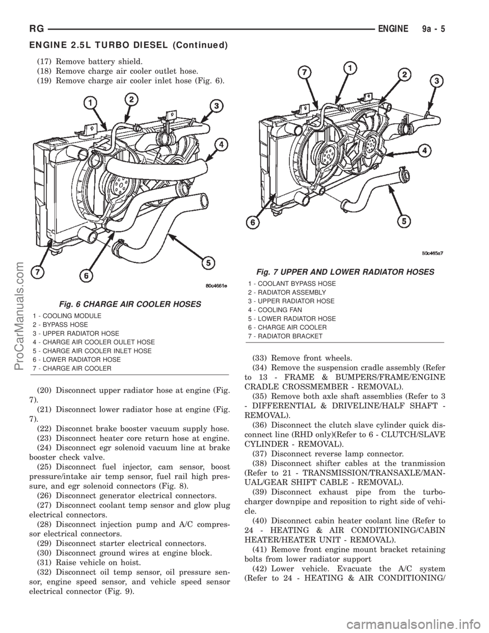
(19) Remove charge air cooler inlet hose (Fig. 6).
(20) Disconnect upper radiator hose at engine (Fig.
7).
(21) Disconnect lower radiator hose at engine (Fig.
7).
(22) Disconnet brake booster vacuum supply hose.
(23) Disconnect heater core return hose at engine.
(24) Disconnect egr solenoid vacuum line at brake
booster check valve.
(25) Disconnect fuel injector, cam sensor, boost
pressure/intake air temp sensor, fuel rail high pres-
sure, and egr solenoid connectors (Fig. 8).
(26) Disconnect generator electrical connectors.
(27) Disconnect coolant temp sensor and glow plug
electrical connectors.
(28) Disconnect injection pump and A/C compres-
sor electrical connectors.
(29) Disconnect starter electrical connectors.
(30) Disconnect ground wires at engine block.
(31) Raise vehicle on hoist.
(32) Disconnect oil temp sensor, oil pressure sen-
sor, engine speed sensor, and vehicle speed sensor
electrical connector (Fig. 9).(33) Remove front wheels.
(34) Remove the suspension cradle assembly (Refer
to 13 - FRAME & BUMPERS/FRAME/ENGINE
CRADLE CROSSMEMBER - REMOVAL).
(35) Remove both axle shaft assemblies (Refer to 3
- DIFFERENTIAL & DRIVELINE/HALF SHAFT -
REMOVAL).
(36) Disconnect the clutch slave cylinder quick dis-
connect line (RHD only)(Refer to 6 - CLUTCH/SLAVE
CYLINDER - REMOVAL).
(37) Disconnect reverse lamp connector.
(38) Disconnect shifter cables at the tranmission
(Refer to 21 - TRANSMISSION/TRANSAXLE/MAN-
UAL/GEAR SHIFT CABLE - REMOVAL).
(39) Disconnect exhaust pipe from the turbo-
charger downpipe and reposition to right side of vehi-
cle.
(40) Disconnect cabin heater coolant line (Refer to
24 - HEATING & AIR CONDITIONING/CABIN
HEATER/HEATER UNIT - REMOVAL).
(41) Remove front engine mount bracket retaining
bolts from lower radiator support
(42) Lower vehicle. Evacuate the A/C system
(Refer to 24 - HEATING & AIR CONDITIONING/
Fig. 6 CHARGE AIR COOLER HOSES
1 - COOLING MODULE
2 - BYPASS HOSE
3 - UPPER RADIATOR HOSE
4 - CHARGE AIR COOLER OULET HOSE
5 - CHARGE AIR COOLER INLET HOSE
6 - LOWER RADIATOR HOSE
7 - CHARGE AIR COOLER
Fig. 7 UPPER AND LOWER RADIATOR HOSES
1 - COOLANT BYPASS HOSE
2 - RADIATOR ASSEMBLY
3 - UPPER RADIATOR HOSE
4 - COOLING FAN
5 - LOWER RADIATOR HOSE
6 - CHARGE AIR COOLER
7 - RADIATOR BRACKET
RGENGINE9a-5
ENGINE 2.5L TURBO DIESEL (Continued)
ProCarManuals.com
Page 1368 of 2399
INSTALLATION
INSTALLATION - 2.5L TURBO DIESEL ENGINE
(1) Reassembly engine and transmission assembly
and install on engine cradle.
(2) Position engine and cradle assembly under
vehicle.
(3) Slowly lower the vehicle down over the engine
and cradle assembly.
(4) Install right engine mount bolts. Torque to
54N´m (40 ft. lbs.)
(5) Install left engine mount through bolt. Torque
to 75N´m (55 ft. lbs.)
(6) Raise vehicle and engine from engine cradle.
(7) Attach front engine mount bracket to lower
radiator support. Torque to 54N´m (40 ft. lbs.)
(8) Connect cabin heater coolant hose.
(9) Connect exhaust pipe to the turbocharger
downpipe flange. Torque to 28 N´m (250 in. lbs.)
(10) Connect reverse lamp electrical connector at
transmission.
(11) Connect both shifter cables (Refer to 21 -
TRANSMISSION/TRANSAXLE/MANUAL/GEAR
SHIFT CABLE - INSTALLATION).
(12) Connect the clutch slave cylinder quick dis-
connect connector (RHD only)(Refer to 6 - CLUTCH/
SLAVE CYLINDER - INSTALLATION).
(13) Install engine harness into bracket on trans-
mission.
(14) Lower vehicle.
(15) Connect fuel supply and return lines.
(16) Connect A/C lines to A/C compressor. Torque
to 23N´m (17 ft. lbs.)
(17) Route engine wiring harnes to proper location.
(18) Connect engine harness ground cables to
engine block
(19) Connect starter solenoid electrical connector
and battery feed wire to starter. Torque to 10N´m (90
in. lbs.)
(20) Connect A/C compressor, injection pump, glow
plugs, and coolant temperature sensor electrical con-
nectors.
(21) Connect generator electrical connector. Torque
to 9N´m (75 in. lbs.)
(22) Connect the fuel injector, fuel pressure sensor,
boost pressure/intake air temp sensor, cam sensor,
and egr solenoid electrical connectors (Fig. 8).
(23) Connect egr solenoid vacuum supply line to
brake boost vacuum supply line.(24) Connect brake booster vacuum supply line.
(25) Connect heater core return hose to coolant
pipe.
(26) Connect lower radiator hose to engine (Fig. 7).
(27) Install charger air cooler inlet hose (Fig. 6).
(28) Install charge air cooler outlet hose (Fig. 6).
(29) Connect upper radiator hose to engine (Fig.
7).
(30) Install battery shield.
(31) Install coolant reserve pressure container
(Refer to 7 - COOLING/ENGINE/COOLANT RECOV-
ERY PRESS CONTAINER - INSTALLATION).
(32) Install power steering reservoir and bracket
(Fig. 4).
(33) Raise vehicle
(34) Connect oil pressure sensor, oil temperature
sensor, engine speed sensor, and vehicle speed sensor
electrical connector (Fig. 9).
(35) Install suspension cradle in vehicle (Refer to
13 - FRAME & BUMPERS/FRAME/ENGINE CRA-
DLE CROSSMEMBER - INSTALLATION).
(36) Install both axle shaft assemblies (Refer to 3 -
DIFFERENTIAL & DRIVELINE/HALF SHAFT -
INSTALLATION).
(37) Connect the power steering supply, pressure,
and return lines to power steering pump (Fig. 4).
(38) Install the power steering line brackets on oil
pan (Fig. 4).
(39) Install lower splash shield and side panels.
(40) Install both front wheel and tire assemblies.
(41) Lower vehicle.
(42) Install air cleaner housing, MAF sensor, and
air intake tube assembly (Fig. 3).
(43) Refill transmission to proper level (Refer to 21
- TRANSMISSION/TRANSAXLE/MANUAL/FLUID -
STANDARD PROCEDURE).
(44) Refill engine coolant (Refer to 7 - COOLING/
ENGINE/COOLANT - STANDARD PROCEDURE).
(45) Recharge A/C system (Refer to 24 - HEATING
& AIR CONDITIONING/PLUMBING/REFRIGER-
ANT - STANDARD PROCEDURE) .
(46) Install engine cover (Refer to 9 - ENGINE -
INSTALLATION) (Fig. 2).
(47) Connect negative battery cable.
INSTALLATION - ENGINE COVER
(1) Install engine cover on engine.
(2) Install the engine cover mounting bolts (Fig.
10).
RGENGINE9a-7
ENGINE 2.5L TURBO DIESEL (Continued)
ProCarManuals.com
Page 1470 of 2399
The PCM compares the upstream and downstream
heated oxygen sensor inputs to measure catalytic con-
vertor efficiency. If the catalyst efficiency drops below
the minimum acceptable percentage, the PCM stores a
diagnostic trouble code in memory, after 2 trips.
During certain idle conditions, the PCM may enter
a variable idle speed strategy. During variable idle
speed strategy the PCM adjusts engine speed based
on the following inputs.
²A/C sense
²Battery voltage
²Battery temperature or Calculated Battery Tem-
perature
²Engine coolant temperature
²Engine run time
²Inlet/Intake air temperature
²Vehicle mileage
ACCELERATION MODE
This is a CLOSED LOOP mode. The PCM recog-
nizes an abrupt increase in Throttle Position sensor
output voltage or MAP sensor output voltage as a
demand for increased engine output and vehicle
acceleration. The PCM increases injector pulse width
in response to increased fuel demand.
²Wide Open Throttle-open loop
DECELERATION MODE
This is a CLOSED LOOP mode. During decelera-
tion the following inputs are received by the PCM:
²A/C sense
²Battery voltage
²Inlet/Intake air temperature
²Engine coolant temperature
²Crankshaft position (engine speed)
²Exhaust gas oxygen content (upstream heated
oxygen sensor)
²Knock sensor
²Manifold absolute pressure
²Throttle position sensor
²IAC motor (solenoid) control changes in response
to MAP sensor feedback
The PCM may receive a closed throttle input from
the Throttle Position Sensor (TPS) when it senses an
abrupt decrease in manifold pressure. This indicates a
hard deceleration (Open Loop). In response, the PCM
may momentarily turn off the injectors. This helps
improve fuel economy, emissions and engine braking.
WIDE-OPEN-THROTTLE MODE
This is an OPEN LOOP mode. During wide-open-
throttle operation, the following inputs are used by
the PCM:
²Inlet/Intake air temperature
²Engine coolant temperature
²Engine speed
²Knock sensor²Manifold absolute pressure
²Throttle position
When the PCM senses a wide-open-throttle condi-
tion through the Throttle Position Sensor (TPS) it de-
energizes the A/C compressor clutch relay. This
disables the air conditioning system and disables
EGR (if equipped).
The PCM adjusts injector pulse width to supply a
predetermined amount of additional fuel, based on
MAP and RPM.
IGNITION SWITCH OFF MODE
When the operator turns the ignition switch to the
OFF position, the following occurs:
²All outputs are turned off, unless 02 Heater
Monitor test is being run. Refer to the Emission sec-
tion for On-Board Diagnostics.
²No inputs are monitored except for the heated
oxygen sensors. The PCM monitors the heating ele-
ments in the oxygen sensors and then shuts down.
FUEL CORRECTION or ADAPTIVE MEMORIES
DESCRIPTION
In Open Loop, the PCM changes pulse width with-
out feedback from the O2 Sensors. Once the engine
warms up to approximately 30 to 35É F, the PCM
goes into closed loopShort Term Correctionand
utilizes feedback from the O2 Sensors. Closed loop
Long Term Adaptive Memoryis maintained above
170É to 190É F unless the PCM senses wide open
throttle. At that time the PCM returns to Open Loop
operation.
OPERATION
Short Term
The first fuel correction program that begins func-
tioning is the short term fuel correction. This system
corrects fuel delivery in direct proportion to the read-
ings from the Upstream O2 Sensor.
The PCM monitors the air/fuel ratio by using the
input voltage from the O2 Sensor. When the voltage
reaches its preset high or low limit, the PCM begins
to add or remove fuel until the sensor reaches its
switch point. The short term corrections then begin.
The PCM makes a series of quick changes in the
injector pulse-width until the O2 Sensor reaches its
opposite preset limit or switch point. The process
then repeats itself in the opposite direction.
Short term fuel correction will keep increasing or
decreasing injector pulse-width based upon the
upstream O2 Sensor input. The maximum range of
authority for short term memory is 25% (+/-) of base
pulse-width. Short term is violated and is lost when
ignition is turned OFF.
RSFUEL INJECTION14-19
FUEL INJECTION (Continued)
ProCarManuals.com
Page 1471 of 2399
Long Term
The second fuel correction program is the long
term adaptive memory. In order to maintain correct
emission throughout all operating ranges of the
engine, a cell structure based on engine rpm and load
(MAP) is used.
Ther number of cells varies upon the driving con-
ditions. Two cells are used only during idle, based
upon TPS and Park/Neutral switch inputs. There
may be two other cells used for deceleration, based
on TPS, engine rpm, and vehicle speed. The other
twelve cells represent a manifold pressure and an
rpm range. Six of the cells are high rpm and the
other six are low rpm. Each of these cells is a specific
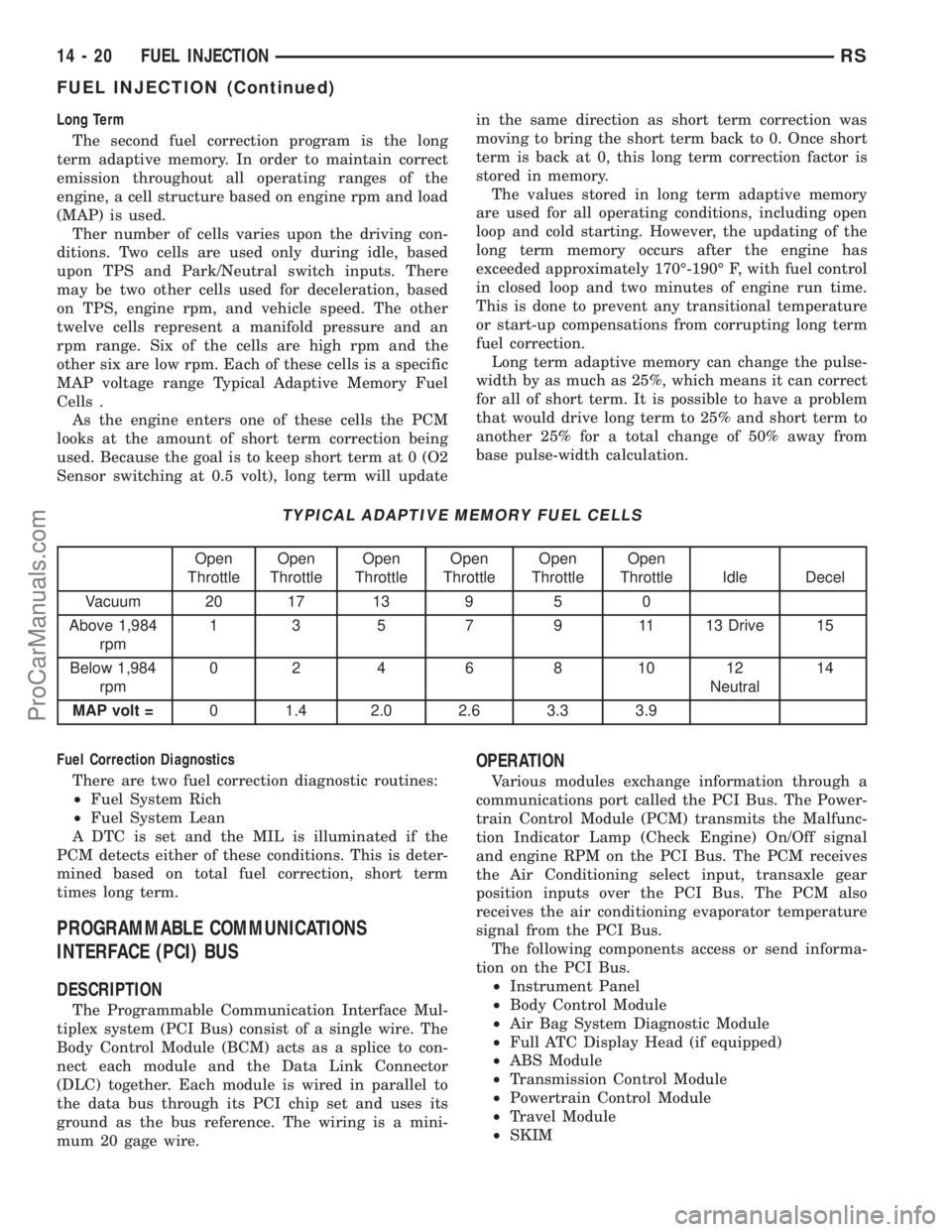
MAP voltage range Typical Adaptive Memory Fuel
Cells .
As the engine enters one of these cells the PCM
looks at the amount of short term correction being
used. Because the goal is to keep short term at 0 (O2
Sensor switching at 0.5 volt), long term will updatein the same direction as short term correction was
moving to bring the short term back to 0. Once short
term is back at 0, this long term correction factor is
stored in memory.
The values stored in long term adaptive memory
are used for all operating conditions, including open
loop and cold starting. However, the updating of the
long term memory occurs after the engine has
exceeded approximately 170É-190É F, with fuel control
in closed loop and two minutes of engine run time.
This is done to prevent any transitional temperature
or start-up compensations from corrupting long term
fuel correction.
Long term adaptive memory can change the pulse-
width by as much as 25%, which means it can correct
for all of short term. It is possible to have a problem
that would drive long term to 25% and short term to
another 25% for a total change of 50% away from
base pulse-width calculation.
TYPICAL ADAPTIVE MEMORY FUEL CELLS
Open
ThrottleOpen
ThrottleOpen
ThrottleOpen
ThrottleOpen
ThrottleOpen
Throttle Idle Decel
Vacuum 20 17 13 9 5 0
Above 1,984
rpm1 3 5 7 9 11 13 Drive 15
Below 1,984
rpm02 4 6 8 1012
Neutral14
MAP volt =0 1.4 2.0 2.6 3.3 3.9
Fuel Correction Diagnostics
There are two fuel correction diagnostic routines:
²Fuel System Rich
²Fuel System Lean
A DTC is set and the MIL is illuminated if the
PCM detects either of these conditions. This is deter-
mined based on total fuel correction, short term
times long term.
PROGRAMMABLE COMMUNICATIONS
INTERFACE (PCI) BUS
DESCRIPTION
The Programmable Communication Interface Mul-
tiplex system (PCI Bus) consist of a single wire. The
Body Control Module (BCM) acts as a splice to con-
nect each module and the Data Link Connector
(DLC) together. Each module is wired in parallel to
the data bus through its PCI chip set and uses its
ground as the bus reference. The wiring is a mini-
mum 20 gage wire.
OPERATION
Various modules exchange information through a
communications port called the PCI Bus. The Power-
train Control Module (PCM) transmits the Malfunc-
tion Indicator Lamp (Check Engine) On/Off signal
and engine RPM on the PCI Bus. The PCM receives
the Air Conditioning select input, transaxle gear
position inputs over the PCI Bus. The PCM also
receives the air conditioning evaporator temperature
signal from the PCI Bus.
The following components access or send informa-
tion on the PCI Bus.
²Instrument Panel
²Body Control Module
²Air Bag System Diagnostic Module
²Full ATC Display Head (if equipped)
²ABS Module
²Transmission Control Module
²Powertrain Control Module
²Travel Module
²SKIM
14 - 20 FUEL INJECTIONRS
FUEL INJECTION (Continued)
ProCarManuals.com
Page 1478 of 2399
FUEL PUMP RELAY
DESCRIPTION
The fuel pump relay is located in the PDC. The
inside top of the PDC cover has a label showing relay
and fuse location.
OPERATION
The fuel pump relay supplies battery voltage to the
fuel pump. A buss bar in the Power Distribution Cen-
ter (PDC) supplies voltage to the solenoid side and
contact side of the relay. The fuel pump relay power
circuit contains a fuse between the buss bar in the
PDC and the relay. The fuse is located in the PDC.
Refer to the Wiring Diagrams for circuit information.
The PCM controls the fuel pump relay by switch-
ing the ground path for the solenoid side of the relay
on and off. The PCM turns the ground path off when
the ignition switch is in the Off position. When the
ignition switch is in the On position, the PCM ener-
gizes the fuel pump. If the crankshaft position sensor
does not detect engine rotation, the PCM de-ener-
gizes the relay after approximately one second.
IDLE AIR CONTROL MOTOR
DESCRIPTION
The idle air control motor is mounted on the throt-
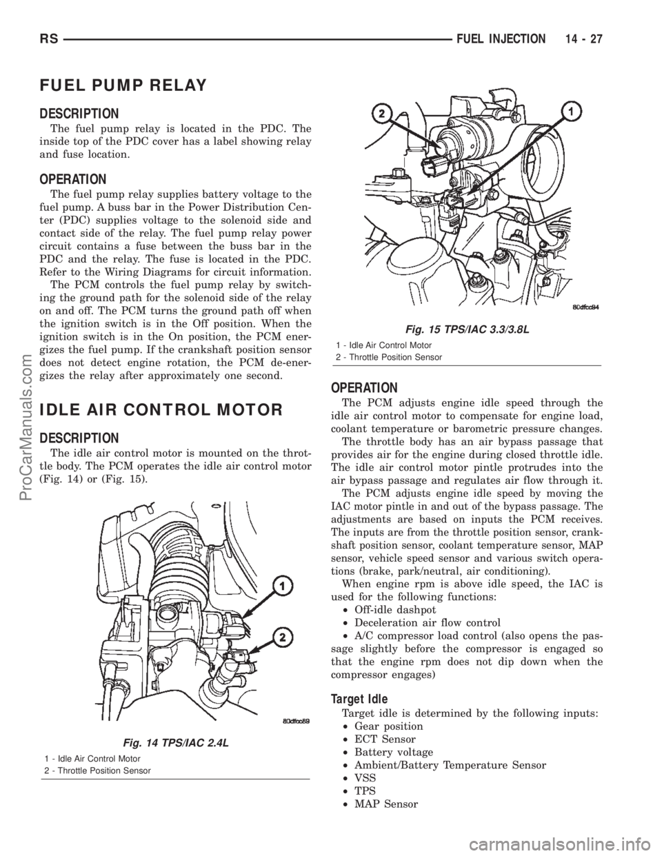
tle body. The PCM operates the idle air control motor
(Fig. 14) or (Fig. 15).
OPERATION
The PCM adjusts engine idle speed through the
idle air control motor to compensate for engine load,
coolant temperature or barometric pressure changes.
The throttle body has an air bypass passage that
provides air for the engine during closed throttle idle.
The idle air control motor pintle protrudes into the
air bypass passage and regulates air flow through it.
The PCM adjusts engine idle speed by moving the
IAC motor pintle in and out of the bypass passage. The
adjustments are based on inputs the PCM receives.
The inputs are from the throttle position sensor, crank-
shaft position sensor, coolant temperature sensor, MAP
sensor, vehicle speed sensor and various switch opera-
tions (brake, park/neutral, air conditioning).
When engine rpm is above idle speed, the IAC is
used for the following functions:
²Off-idle dashpot
²Deceleration air flow control
²A/C compressor load control (also opens the pas-
sage slightly before the compressor is engaged so
that the engine rpm does not dip down when the
compressor engages)
Target Idle
Target idle is determined by the following inputs:
²Gear position
²ECT Sensor
²Battery voltage
²Ambient/Battery Temperature Sensor
²VSS
²TPS
²MAP Sensor
Fig. 14 TPS/IAC 2.4L
1 - Idle Air Control Motor
2 - Throttle Position Sensor
Fig. 15 TPS/IAC 3.3/3.8L
1 - Idle Air Control Motor
2 - Throttle Position Sensor
RSFUEL INJECTION14-27
ProCarManuals.com
Page 1509 of 2399
CONDITION POSSIBLE CAUSES CORRECTION
2. Steering column lower bearing
spring retainer slipped on steering
column shaft.2. Replace steering column.
3. Loose steering column to
instrument panel fasteners.3. Tighten fasteners to specified torque.
STEERING WHEEL, DASH
OR VEHICLE VIBRATES
DURING LOW SPEED OR
STANDSTILL STEERING
MANEUVERS.1. Air in the fluid of the power
steering system.1. Bleed air from system following the
power steering pump initial operation
service procedure.*
2. Tires not properly inflated. 2. Inflate tires to the specified pressure.
3. Excessive engine vibration. 3. Ensure that the engine is tuned properly.
4. Loose tie rod end jam nut. 4. Tighten the inner to outer tie rod jam nut
to the specified torque.
5.Overcharged air conditioning
system.5.Check air conditioning pump head
pressure and correct as necessary.
6. Grounded engine mount. 6. Repair as necessary.
7. Loose outer tie rod. 7. Replace outer tie rod.
STEERING CATCHES,
SURGES OR STICKS IN
CERTAIN POSITIONS OR
IS DIFFICULT TO TURN.
***1. Low power steering fluid level. 1. Fill power steering fluid reservoir to
specified level and check for leaks.
2. Tires not inflated to specified
pressure.2. Inflate tires to the specified pressure.
3. Lack of lubrication in front lower
control arm ball joints.3. Lubricate ball joints if ball joints are not a
lubricated-for-life type ball joint. If ball joint
is a lubricated-for-life ball joint, replace ball
joint.
4. Worn or binding lower control arm
ball joint.4. Replace lower control arm ball joint.
5. Lack of lubrication in steering gear
outer tie rod ends.5. Lubricate tie rod ends if they are not a
lubricated-for-life type. If tie rod end is a
lubricated-for-life type, replace tie rod end.
6. Loose power steering pump drive
belt.6. Tighten the power steering pump drive
belt to specifications or replace automatic
tensioner where applicable. If drive belt is
worn or glazed, replace belt.
7. Faulty power steering pump
(Perform Power Steering Flow and
Pressure Test).7. Replace power steering pump.
8. Faulty power steering gear
(Perform Power Steering Flow and
Pressure Test).8. Replace power steering gear.
9. Excessive friction in steering
column or intermediate shaft/coupler.9. Isolate and correct condition.
10. Excessive friction in power
steering gear.10. Replace power steering gear.
19 - 6 STEERINGRS
STEERING (Continued)
ProCarManuals.com
Page 2061 of 2399
(2) Engage hook retainer attaching front of trim
bolster to quarter trim panel, if applicable.
(3) Engage hidden clips attaching trim bolster to
quarter trim panel.
RIGHT QUARTER TRIM PANEL
REMOVAL
CAUTION: Disconnect the battery negative cable.
Damage to accessory feed circuit can result.
(1) Remove first row seat.
(2) Remove second row seat.
(3) Remove sliding door sill trim panel.
(4) Remove quarter trim bolster.
(5) Remove D-pillar trim panel.
(6) Remove first row seat belt anchor.
(7) Remove second row seat belt anchor.
(8) Remove screws attaching quarter trim to quar-
ter panel from bolster area.
(9) Remove screws attaching rear edge of quarter
trim to attaching bracket.
(10) Disengage hidden clips attaching front of
quarter trim to quarter panel rearward of sliding
door opening and at locators.
(11) Remove quarter trim from quarter panel.
(12) Disconnect speaker wire connector on LWB
quarter trim panel with rear air conditioning.
(13) Pass second row seat belt through slot in trim
panel on long wheel base vehicle.
(14) Pass first row seat belt through slot in trim
panel.
(15) Remove quarter trim panel from vehicle.
INSTALLATION
(1) Position quarter trim panel on vehicle.
(2) Pass first row seat belt through slot in trim
panel.
(3) Pass second row seat belt through access hole
in trim panel on long wheel base vehicle.
(4) Connect wire connector into speaker on LWB
with rear air conditioning.
(5) Align locating pins on backside of trim panel to
mating holes in inner quarter panel.
(6) Engage hidden clips attaching front of quarter
trim to quarter panel rearward of sliding door open-
ing and at locators.
(7) Install screws attaching rear edge of quarter
trim to attaching bracket.
(8) Install screws attaching quarter trim to inner
quarter panel in bolster area.
(9) Install second row seat belt anchor on long
wheel base vehicle. Tighten all seat belt bolts to 39
N´m (29 ft. lbs.) torque.
(10) Install first row seat belt anchor.(11) Install D-pillar trim panel.
(12) Install C-pillar trim panel.
(13) Install quarter trim bolster.
(14) Install sliding door sill trim panel.
(15) Install second row seat, if equipped.
(16) Install first row seat.
(17) Connect the battery negative cable.
LEFT QUARTER TRIM PANEL
REMOVAL
CAUTION: Disconnect the negative cable clamp
from battery post. Damage to accessory feed circuit
can result.
(1) Remove first row seat.
(2) Remove second row seat, if equipped.
(3) Remove front door sill plate on three door vehi-
cle.
(4) Remove sliding door sill plate on four door
vehicle.
(5) Remove left quarter trim bolster.
(6) Remove C-pillar trim panel.
(7) Remove left D-pillar trim panel.
(8) Remove first row seat belt anchor.
(9) Remove second row seat belt anchor on long
wheel base vehicle.
(10) Remove screws attaching quarter trim to
quarter panel from bolster area.
(11) Remove screws attaching rear edge of quarter
trim to attaching bracket or inner quarter trim
panel.
(12) Disconnect wire connector from accessory
power outlet, if equipped.
(13) Remove quarter trim from quarter panel.
(14) Pass front seat belt and turning loop through
slot in quarter trim panel on three door vehicle.
(15) Pass first row seat belt through slot in quar-
ter trim panel.
(16) Pass second row seat belt, if equipped,
through slot in quarter trim panel on long wheel
base vehicle.
(17) Remove quarter trim panel from vehicle.
INSTALLATION
(1) Position quarter trim panel on vehicle.
(2) Pass second row seat belt, if equipped, through
slot in quarter trim panel on long wheel base vehicle.
(3) Pass first row seat belt through slot in quarter
trim panel.
(4) Connect wire connector into accessory power
outlet, if equipped.
(5) Align locating pins on backside of trim panel to
mating holes in inner panels.
23 - 78 INTERIORRS
QUARTER TRIM BOLSTER (Continued)
ProCarManuals.com
Page 2244 of 2399
HEATING & AIR CONDITIONING
TABLE OF CONTENTS
page page
HEATING & AIR CONDITIONING
DESCRIPTION
DESCRIPTION - SINGLE ZONE...........1
DESCRIPTION - DUAL ZONE.............1
DESCRIPTION - MANUAL THREE ZONE.....1
DESCRIPTION - THREE ZONE AUTOMATIC
TEMPERATURE CONTROL...............2
OPERATION
OPERATION - DUAL ZONE...............3
OPERATION - MANUAL THREE ZONE......3
OPERATION - THREE ZONE ATC..........4
DIAGNOSIS AND TESTING
DIAGNOSIS AND TESTING - A/C COOL
DOWN TEST..........................5DIAGNOSIS AND TESTING - A/C
PERFORMANCE TEST..................5
DIAGNOSIS AND TESTING - HEATER
PERFORMANCE TEST..................6
SPECIFICATIONS - HEATER-A/C SYSTEM.....7
CONTROLS - FRONT......................8
CONTROLS - REAR......................29
DISTRIBUTION - FRONT...................39
DISTRIBUTION - REAR....................51
PLUMBING - FRONT.....................59
PLUMBING - REAR......................97
DIESEL SUPPLEMENTAL HEATER - DCHA -
BUX.................................109
HEATING & AIR
CONDITIONING
DESCRIPTION
DESCRIPTION - SINGLE ZONE
A single zone heating and air conditioning system
allows one temperature setting for the entire vehicle.
The full range of temperatures that the system can
produce are available by rotating the temperature
control located in control panel.
The control panel and integral computer is
mounted in the instrument panel.
DESCRIPTION - DUAL ZONE
A manual Dual Zone Heating and Air Conditioning
system allows completely independent side-to-side
tempeture control of the discharge air.
The Dual Zone Heating and Air Conditioning sys-
tem includes a dust and odor air filter. The filter ele-
ment is the same size as the air conditioning
evaporator to ensure ample capacity. A door at the
base of the heating and air conditioning housing
below the glove box provides easy access to the filter
element.
The control panel and integral computer is located
in the instrument panel.
The instrument panel mounted control and inte-
gral computer contains:
²a power button which allows the system to be
completely turned off. Contains an LED that illumi-
nates to show when the function is operational.²rear window defogger on/off switch. Contains an
LED that illuminates to show when the function is
operational.
²slide controls for completely independent side-to-
side temperature control of the discharged air. The
full range of temperature that the system can pro-
duce in any mode is available on either side of the
vehicle by independently positioning the slide con-
trols on the instrument panel.
²air recirculation on/off switch. The Recirculate
button contains an LED that illuminates to show
when the function is in operation.
²air conditioning on/off switch. The Snowflake
button contains an LED that illuminates to shown
when the function is in operation.
²rotary knob for fan speed selection.
²a rotary knob for mode control.
DESCRIPTION - MANUAL THREE ZONE
The fully adjustable Three-Zone front and rear
heating and air conditioning system allows interme-
diate seat passengers the ability to regulate air tem-
perature as well as fan speed. All controls are
identified by ISO graphic symbols.
The Three Zone Heating and Air Conditioning sys-
tem includes a dust and odor air filter. The filter ele-
ment is the same size as the air conditioning
evaporator to ensure ample capacity. A door at the
base of the heating and air conditioning housing
below the glove box provides easy access to the filter
element.
RSHEATING & AIR CONDITIONING24-1
ProCarManuals.com