2002 CHRYSLER CARAVAN wheel
[x] Cancel search: wheelPage 1538 of 2399
(1) Install outer tie rod onto inner tie rod.
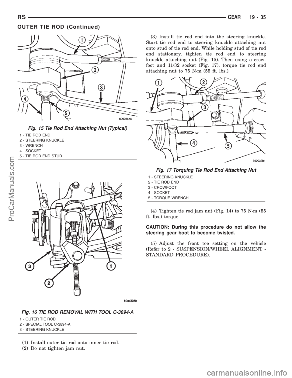
(2) Do not tighten jam nut.(3) Install tie rod end into the steering knuckle.
Start tie rod end to steering knuckle attaching nut
onto stud of tie rod end. While holding stud of tie rod
end stationary, tighten tie rod end to steering
knuckle attaching nut (Fig. 15). Then using a crow-
foot and 11/32 socket (Fig. 17), torque tie rod end
attaching nut to 75 N´m (55 ft. lbs.).
(4) Tighten tie rod jam nut (Fig. 14) to 75 N´m (55
ft. lbs.) torque.
CAUTION: During this procedure do not allow the
steering gear boot to become twisted.
(5) Adjust the front toe setting on the vehicle
(Refer to 2 - SUSPENSION/WHEEL ALIGNMENT -
STANDARD PROCEDURE).
Fig. 15 Tie Rod End Attaching Nut (Typical)
1 - TIE ROD END
2 - STEERING KNUCKLE
3 - WRENCH
4 - SOCKET
5 - TIE ROD END STUD
Fig. 16 TIE ROD REMOVAL WITH TOOL C-3894-A
1 - OUTER TIE ROD
2 - SPECIAL TOOL C-3894-A
3 - STEERING KNUCKLE
Fig. 17 Torquing Tie Rod End Attaching Nut
1 - STEERING KNUCKLE
2 - TIE ROD END
3 - CROWFOOT
4 - SOCKET
5 - TORQUE WRENCH
RSGEAR19-35
OUTER TIE ROD (Continued)
ProCarManuals.com
Page 1541 of 2399
(2) Fill the fluid reservoir to the proper level and
let the fluid settle for at least two (2) minutes.
(3) Start the engine and let run for a few seconds,
then turn the engine off.
(4) Add fluid if necessary. Repeat the above steps
until the fluid level remains constant after running
the engine.
(5) Raise the front wheels off the ground.
(6) Start the engine.
(7) Slowly turn the steering wheel right and left,
lightly contacting the wheel stops.
(8) Add fluid if necessary.
(9) Lower the vehicle, then turn the steering wheel
slowly from lock-to-lock.
(10) Stop the engine. Check the fluid level and
refill as required.
(11) If the fluid is extremely foamy, allow the vehi-
cle to stabilize a few minutes, then repeat the above
procedure.
REMOVAL
REMOVAL - PUMP (2.4L ENGINE)
(1) Remove the (-) negative battery cable from the
battery and isolate cable.
(2) Remove the cap from the power steering fluid
reservoir.
(3) Using a siphon pump, remove as much power
steering fluid as possible from the power steering
fluid reservoir.
(4) Raise the vehicle on jack stands or centered on
a frame contact type hoist. See Hoisting in Lubrica-
tion and Maintenance.
(5) Disconnect the oxygen sensor wiring harness
from the vehicle wiring harness at the rear engine
mount bracket.
NOTE: The exhaust system needs to be removed
from the engine to allow for an area to remove the
power steering pump from the vehicle.
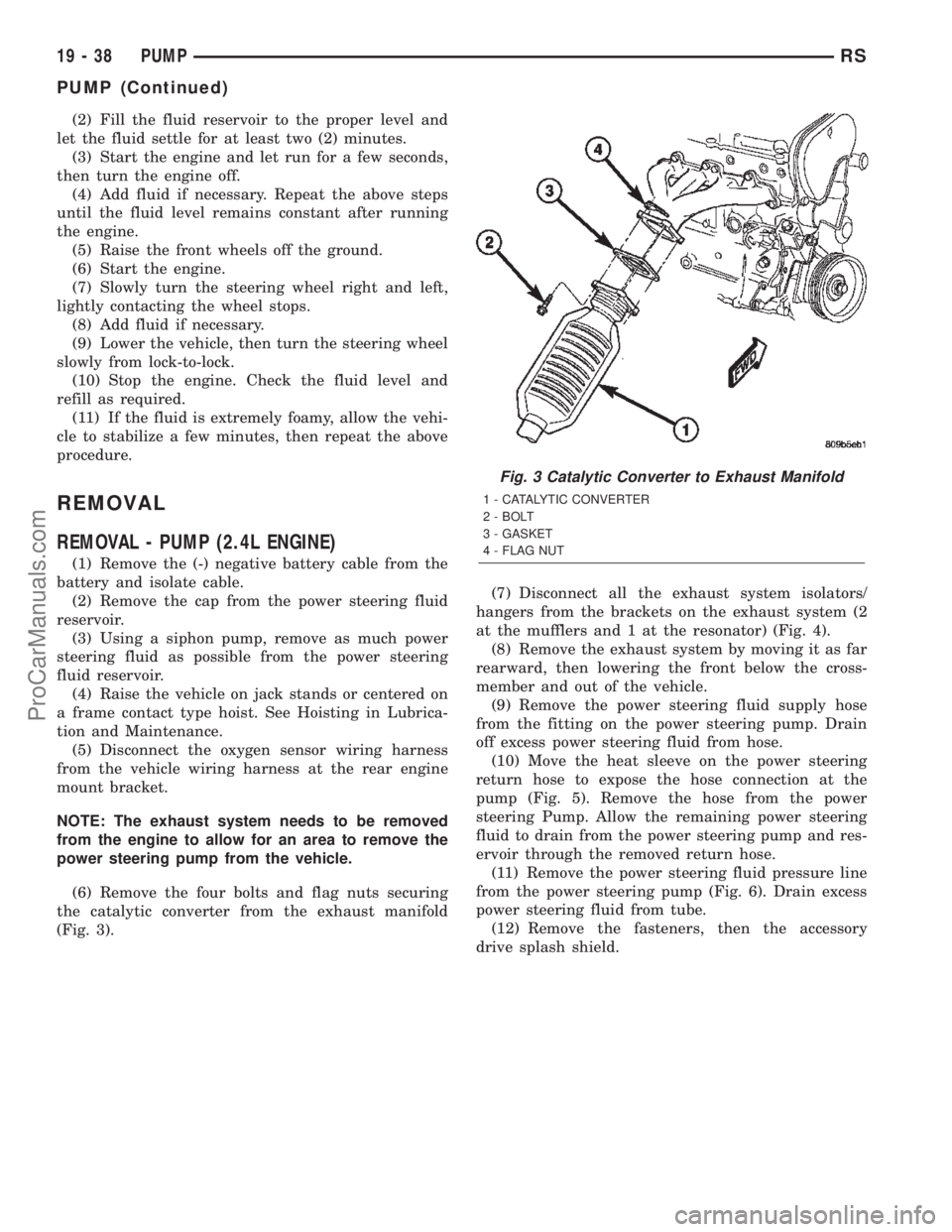
(6) Remove the four bolts and flag nuts securing
the catalytic converter from the exhaust manifold
(Fig. 3).(7) Disconnect all the exhaust system isolators/
hangers from the brackets on the exhaust system (2
at the mufflers and 1 at the resonator) (Fig. 4).
(8) Remove the exhaust system by moving it as far
rearward, then lowering the front below the cross-
member and out of the vehicle.
(9) Remove the power steering fluid supply hose
from the fitting on the power steering pump. Drain
off excess power steering fluid from hose.
(10) Move the heat sleeve on the power steering
return hose to expose the hose connection at the
pump (Fig. 5). Remove the hose from the power
steering Pump. Allow the remaining power steering
fluid to drain from the power steering pump and res-
ervoir through the removed return hose.
(11) Remove the power steering fluid pressure line
from the power steering pump (Fig. 6). Drain excess
power steering fluid from tube.
(12) Remove the fasteners, then the accessory
drive splash shield.
Fig. 3 Catalytic Converter to Exhaust Manifold
1 - CATALYTIC CONVERTER
2 - BOLT
3 - GASKET
4 - FLAG NUT
19 - 38 PUMPRS
PUMP (Continued)
ProCarManuals.com
Page 1560 of 2399
OPERATION
The Transfer Unit provides the power to the rear
wheels through a hypoid ring gear and pinion set.
DIAGNOSIS AND TESTING
SEAL IDENTIFICATION
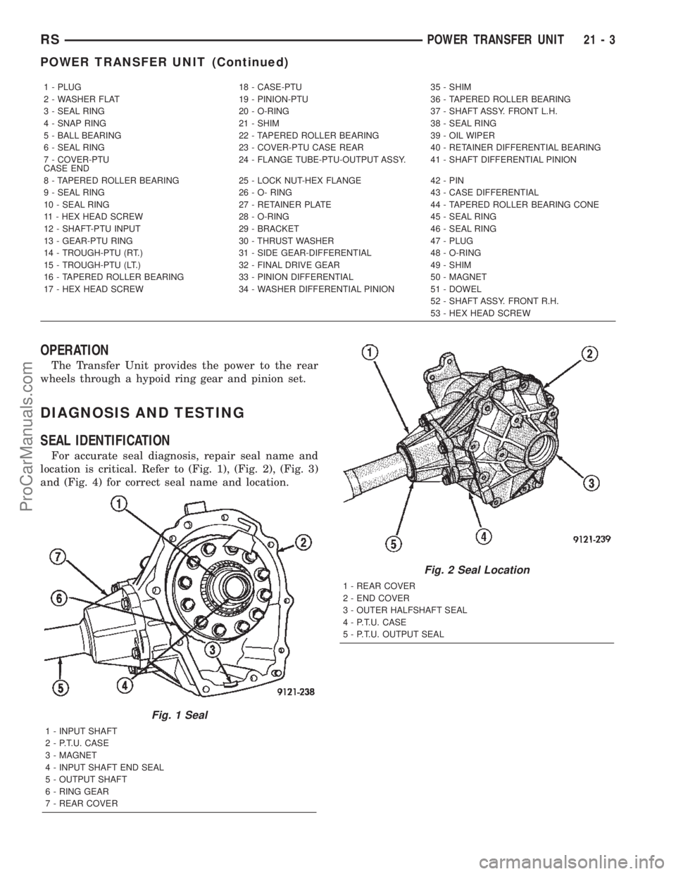
For accurate seal diagnosis, repair seal name and
location is critical. Refer to (Fig. 1), (Fig. 2), (Fig. 3)
and (Fig. 4) for correct seal name and location.
1 - PLUG 18 - CASE-PTU 35 - SHIM
2 - WASHER FLAT 19 - PINION-PTU 36 - TAPERED ROLLER BEARING
3 - SEAL RING 20 - O-RING 37 - SHAFT ASSY. FRONT L.H.
4 - SNAP RING 21 - SHIM 38 - SEAL RING
5 - BALL BEARING 22 - TAPERED ROLLER BEARING 39 - OIL WIPER
6 - SEAL RING 23 - COVER-PTU CASE REAR 40 - RETAINER DIFFERENTIAL BEARING
7 - COVER-PTU
CASE END24 - FLANGE TUBE-PTU-OUTPUT ASSY. 41 - SHAFT DIFFERENTIAL PINION
8 - TAPERED ROLLER BEARING 25 - LOCK NUT-HEX FLANGE 42 - PIN
9 - SEAL RING 26 - O- RING 43 - CASE DIFFERENTIAL
10 - SEAL RING 27 - RETAINER PLATE 44 - TAPERED ROLLER BEARING CONE
11 - HEX HEAD SCREW 28 - O-RING 45 - SEAL RING
12 - SHAFT-PTU INPUT 29 - BRACKET 46 - SEAL RING
13 - GEAR-PTU RING 30 - THRUST WASHER 47 - PLUG
14 - TROUGH-PTU (RT.) 31 - SIDE GEAR-DIFFERENTIAL 48 - O-RING
15 - TROUGH-PTU (LT.) 32 - FINAL DRIVE GEAR 49 - SHIM
16 - TAPERED ROLLER BEARING 33 - PINION DIFFERENTIAL 50 - MAGNET
17 - HEX HEAD SCREW 34 - WASHER DIFFERENTIAL PINION 51 - DOWEL
52 - SHAFT ASSY. FRONT R.H.
53 - HEX HEAD SCREW
Fig. 1 Seal
1 - INPUT SHAFT
2 - P.T.U. CASE
3 - MAGNET
4 - INPUT SHAFT END SEAL
5 - OUTPUT SHAFT
6 - RING GEAR
7 - REAR COVER
Fig. 2 Seal Location
1 - REAR COVER
2 - END COVER
3 - OUTER HALFSHAFT SEAL
4 - P.T.U. CASE
5 - P.T.U. OUTPUT SEAL
RSPOWER TRANSFER UNIT21-3
POWER TRANSFER UNIT (Continued)
ProCarManuals.com
Page 1563 of 2399
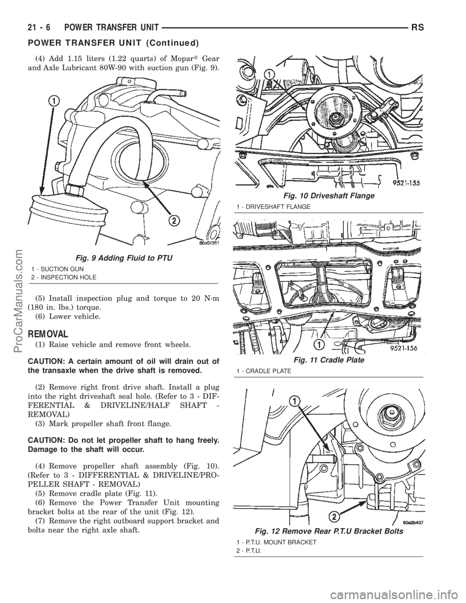
(4) Add 1.15 liters (1.22 quarts) of MopartGear
and Axle Lubricant 80W-90 with suction gun (Fig. 9).
(5) Install inspection plug and torque to 20 N´m
(180 in. lbs.) torque.
(6) Lower vehicle.
REMOVAL
(1) Raise vehicle and remove front wheels.
CAUTION: A certain amount of oil will drain out of
the transaxle when the drive shaft is removed.
(2) Remove right front drive shaft. Install a plug
into the right driveshaft seal hole. (Refer to 3 - DIF-
FERENTIAL & DRIVELINE/HALF SHAFT -
REMOVAL)
(3) Mark propeller shaft front flange.
CAUTION: Do not let propeller shaft to hang freely.
Damage to the shaft will occur.
(4) Remove propeller shaft assembly (Fig. 10).
(Refer to 3 - DIFFERENTIAL & DRIVELINE/PRO-
PELLER SHAFT - REMOVAL)
(5) Remove cradle plate (Fig. 11).
(6) Remove the Power Transfer Unit mounting
bracket bolts at the rear of the unit (Fig. 12).
(7) Remove the right outboard support bracket and
bolts near the right axle shaft.
Fig. 11 Cradle Plate
1 - CRADLE PLATE
Fig. 12 Remove Rear P.T.U Bracket Bolts
1 - P.T.U. MOUNT BRACKET
2 - P.T.U.
Fig. 9 Adding Fluid to PTU
1 - SUCTION GUN
2 - INSPECTION HOLE
Fig. 10 Driveshaft Flange
1 - DRIVESHAFT FLANGE
21 - 6 POWER TRANSFER UNITRS
POWER TRANSFER UNIT (Continued)
ProCarManuals.com
Page 1579 of 2399
ASSEMBLY...........................115
SHIFT INTERLOCK SOLENOID
DESCRIPTION........................115
OPERATION..........................115
DIAGNOSIS AND TESTING - BRAKE/
TRANSMISSION SHIFT INTERLOCK
SOLENOID..........................117
REMOVAL............................117
INSTALLATION........................118
SOLENOID - TCC
DESCRIPTION........................119
OPERATION..........................119
REMOVAL............................119
INSTALLATION........................120
THROTTLE VALVE CABLE
REMOVAL............................120
INSTALLATION........................121
ADJUSTMENTS
THROTTLE VALVE LINKAGE
ADJUSTMENT.......................122
TORQUE CONVERTER
DESCRIPTION........................122
OPERATION..........................126
REMOVAL............................127
INSTALLATION........................127
TRANSFER SYSTEM - OUTPUT SHAFT/GEAR/
BEARING
REMOVAL............................128INSTALLATION........................131
ADJUSTMENTS
ADJUSTMENT - OUTPUT SHAFT BEARING . 135
TRANSFER SYSTEM - TRANSFER SHAFT/
GEAR/BEARING
REMOVAL............................137
INSTALLATION........................141
ADJUSTMENTS
ADJUSTMENT - TRANSFER SHAFT
BEARING...........................145
VALVE BODY
REMOVAL............................146
DISASSEMBLY........................148
CLEANING...........................154
INSPECTION.........................155
ASSEMBLY...........................155
INSTALLATION........................158
ADJUSTMENTS
HYDRAULIC CONTROL PRESSURE
ADJUSTMENTS......................160
VEHICLE SPEED SENSOR/PINION GEAR
REMOVAL............................160
INSTALLATION........................160
31TH AUTOMATIC
TRANSAXLE
DESCRIPTION
This transaxle combines torque converter, three
speed transmission, final drive gearing, and differen-
tial into a front wheel drive system.
Within this transaxle, there are three primary
areas:
(1) Main center line plus valve body.
(2) Transfer shaft center line (includes governor
and parking sprag).
(3) Differential center line.
Center distances between the main rotating parts
in these three areas are held precise to maintain a
low noise level.
The torque converter, transaxle area, and differen-
tial are housed in an integral aluminum die casting.
The differential oil sump is common with the
transaxle sump. Separate filling of the differen-
tial is NOT necessary.
The torque converter is attached to the crankshaft
through a flexible driving plate. Cooling of the con-
verter is accomplished by circulating the transaxle
fluid through a remote cooler. There are two types of
coolers used. An oil-to-water type cooler located in
the radiator side tank and/or an oil-to-air heatexchanger. The torque converter assembly is a sealed
unit that cannot be disassembled.
The transaxle fluid is filtered by an internal filter
attached to the lower side of the valve body assembly.
Engine torque is transmitted to the torque con-
verter and then through the input shaft to multiple-
disc clutches in the transaxle. The power flow
depends on the application of the clutches and bands.
Refer to Elements in Use Chart in Diagnosis and
Tests section.
The transaxle consists of:
²Two multiple-disc clutches
²An overrunning clutch
²Two servos
²A hydraulic accumulator
²Two bands
²Two planetary gear sets
This provides three forward ratios and a reverse
ratio. The common sun gear of the planetary gear
sets is connected to the front clutch by a driving
shell. The driving shell is splined to the sun gear and
front clutch retainer. The hydraulic system consists
of an oil pump and a single valve body which con-
tains all of the valves except the governor valves.
The transaxle sump and differential sump are both
vented through the dipstick. Output torque from the
main center line is delivered through helical gears to
the transfer shaft. This gear set is a factor in the
transaxle final drive (axle) ratio. The shaft also car-
21 - 22 31TH AUTOMATIC TRANSAXLERS
ProCarManuals.com
Page 1589 of 2399
CLUTCHES BANDS
LEVER START PARK
FRONT REAR LOCKUPOVER-
RUNNING(KICKDOWN) LOW/REV
POSITION SAFETY SPRAG FRONT REAR
P - PARK X X
R-
REVERSEXX
N-
NEUTRALX
D - DRIVE
First X X
Second X X
Third X X X
2-
SECOND
First X X
Second X X
1 - Low X X
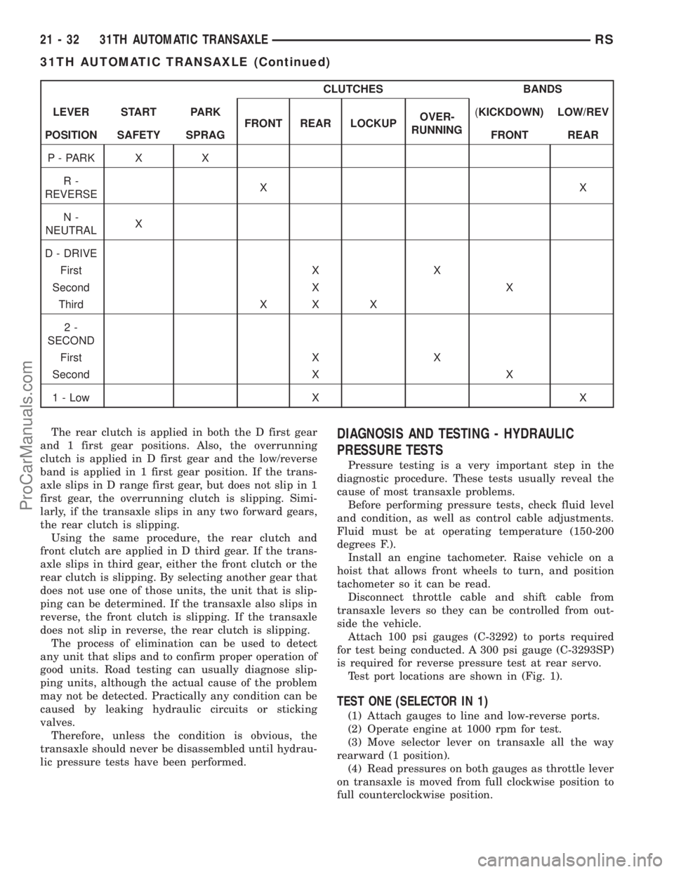
The rear clutch is applied in both the D first gear
and 1 first gear positions. Also, the overrunning
clutch is applied in D first gear and the low/reverse
band is applied in 1 first gear position. If the trans-
axle slips in D range first gear, but does not slip in 1
first gear, the overrunning clutch is slipping. Simi-
larly, if the transaxle slips in any two forward gears,
the rear clutch is slipping.
Using the same procedure, the rear clutch and
front clutch are applied in D third gear. If the trans-
axle slips in third gear, either the front clutch or the
rear clutch is slipping. By selecting another gear that
does not use one of those units, the unit that is slip-
ping can be determined. If the transaxle also slips in
reverse, the front clutch is slipping. If the transaxle
does not slip in reverse, the rear clutch is slipping.
The process of elimination can be used to detect
any unit that slips and to confirm proper operation of
good units. Road testing can usually diagnose slip-
ping units, although the actual cause of the problem
may not be detected. Practically any condition can be
caused by leaking hydraulic circuits or sticking
valves.
Therefore, unless the condition is obvious, the
transaxle should never be disassembled until hydrau-
lic pressure tests have been performed.
DIAGNOSIS AND TESTING - HYDRAULIC
PRESSURE TESTS
Pressure testing is a very important step in the
diagnostic procedure. These tests usually reveal the
cause of most transaxle problems.
Before performing pressure tests, check fluid level
and condition, as well as control cable adjustments.
Fluid must be at operating temperature (150-200
degrees F.).
Install an engine tachometer. Raise vehicle on a
hoist that allows front wheels to turn, and position
tachometer so it can be read.
Disconnect throttle cable and shift cable from
transaxle levers so they can be controlled from out-
side the vehicle.
Attach 100 psi gauges (C-3292) to ports required
for test being conducted. A 300 psi gauge (C-3293SP)
is required for reverse pressure test at rear servo.
Test port locations are shown in (Fig. 1).
TEST ONE (SELECTOR IN 1)
(1) Attach gauges to line and low-reverse ports.
(2) Operate engine at 1000 rpm for test.
(3) Move selector lever on transaxle all the way
rearward (1 position).
(4) Read pressures on both gauges as throttle lever
on transaxle is moved from full clockwise position to
full counterclockwise position.
21 - 32 31TH AUTOMATIC TRANSAXLERS
31TH AUTOMATIC TRANSAXLE (Continued)
ProCarManuals.com
Page 1596 of 2399
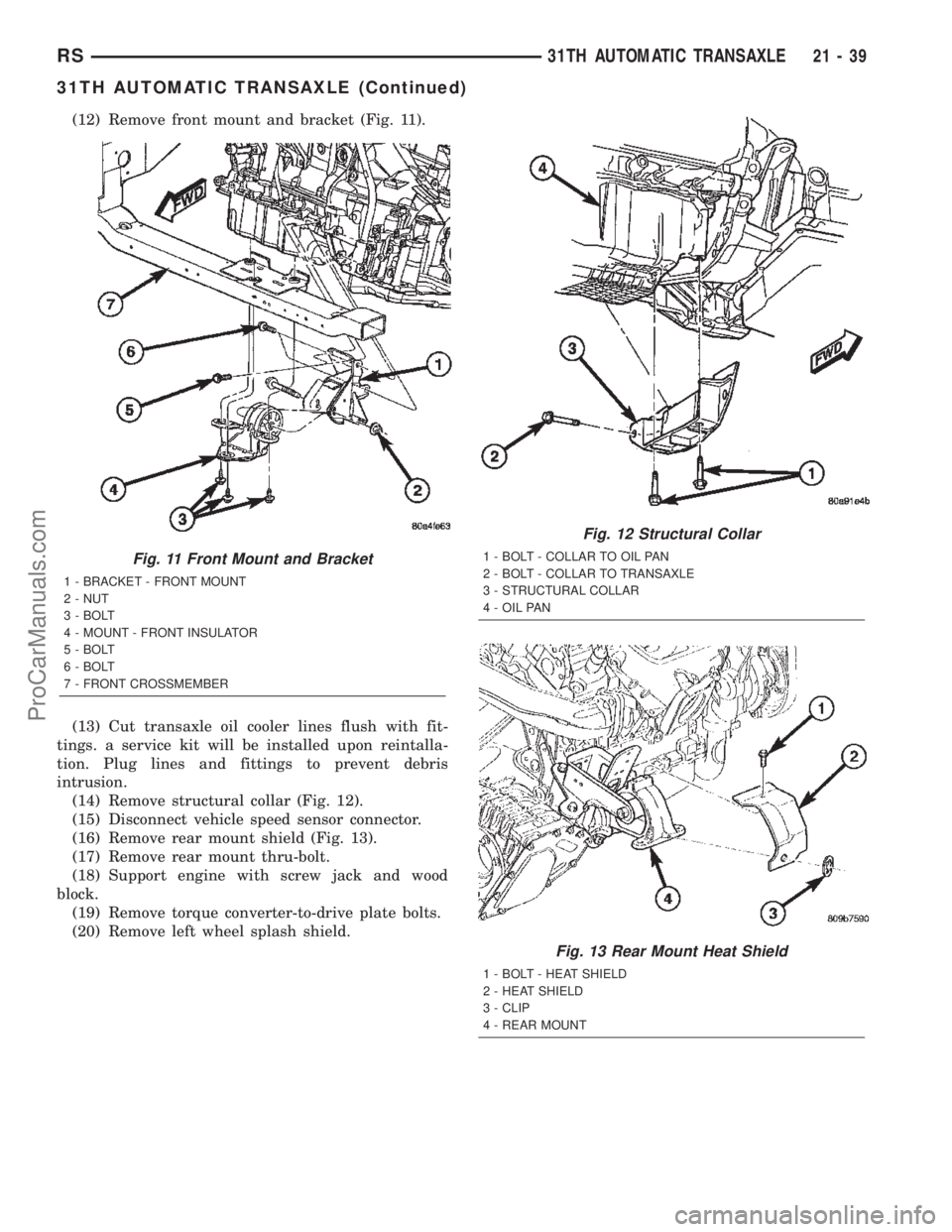
(12) Remove front mount and bracket (Fig. 11).
(13) Cut transaxle oil cooler lines flush with fit-
tings. a service kit will be installed upon reintalla-
tion. Plug lines and fittings to prevent debris
intrusion.
(14) Remove structural collar (Fig. 12).
(15) Disconnect vehicle speed sensor connector.
(16) Remove rear mount shield (Fig. 13).
(17) Remove rear mount thru-bolt.
(18) Support engine with screw jack and wood
block.
(19) Remove torque converter-to-drive plate bolts.
(20) Remove left wheel splash shield.
Fig. 11 Front Mount and Bracket
1 - BRACKET - FRONT MOUNT
2 - NUT
3 - BOLT
4 - MOUNT - FRONT INSULATOR
5 - BOLT
6 - BOLT
7 - FRONT CROSSMEMBER
Fig. 12 Structural Collar
1 - BOLT - COLLAR TO OIL PAN
2 - BOLT - COLLAR TO TRANSAXLE
3 - STRUCTURAL COLLAR
4 - OIL PAN
Fig. 13 Rear Mount Heat Shield
1 - BOLT - HEAT SHIELD
2 - HEAT SHIELD
3 - CLIP
4 - REAR MOUNT
RS31TH AUTOMATIC TRANSAXLE21-39
31TH AUTOMATIC TRANSAXLE (Continued)
ProCarManuals.com
Page 1618 of 2399

INSTALLATION
(1) Install transaxle assembly to engine using a
transmission jack and helper.
(2) Install and torque transaxle-to-engine bolts to
95 N´m (70 ft. lbs.).
(3) Using screw jack and wood block, raise engine/
transaxle assembly into position and install left
upper mount thru-bolt (Fig. 97). Torque bolt to 75
N´m (55 ft. lbs.).
(4) Install left wheel splash shield.
(5) Install torque converter-to-drive plate bolts and
torque to 88 N´m (65 ft. lbs.).
(6) Install rear mount bracket to transaxle (Fig.
98). Install bolts by hand but do not tighten at this
time.
(7) Align rear mount bracket to mount and install
thru-bolt. Do not tighten at this time.
(8) Connect vehicle speed sensor connector.
Fig. 97 Left Mount-to-Rail
1 - FRAME BRACKET
2 - FRAME RAIL - LEFT
3 - BOLT
4 - TRANSAXLE MOUNT
Fig. 98 Rear Mount Bracket
1 - BOLT - VERTICAL
2 - BRACKET - REAR MOUNT3 - BOLT - HORIZONTAL
RS31TH AUTOMATIC TRANSAXLE21-61
31TH AUTOMATIC TRANSAXLE (Continued)
ProCarManuals.com