2002 CHRYSLER CARAVAN sensor
[x] Cancel search: sensorPage 1385 of 2399
CYLINDER HEAD COVER(S)
DESCRIPTION
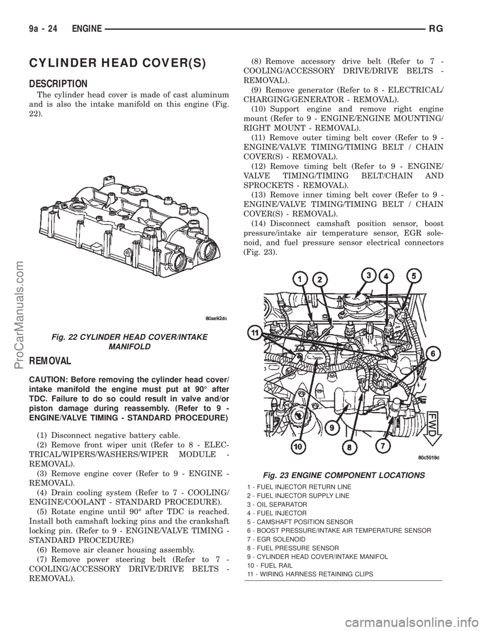
The cylinder head cover is made of cast aluminum
and is also the intake manifold on this engine (Fig.
22).
REMOVAL
CAUTION: Before removing the cylinder head cover/
intake manifold the engine must put at 90É after
TDC. Failure to do so could result in valve and/or
piston damage during reassembly. (Refer to 9 -
ENGINE/VALVE TIMING - STANDARD PROCEDURE)
(1) Disconnect negative battery cable.
(2) Remove front wiper unit (Refer to 8 - ELEC-
TRICAL/WIPERS/WASHERS/WIPER MODULE -
REMOVAL).
(3) Remove engine cover (Refer to 9 - ENGINE -
REMOVAL).
(4) Drain cooling system (Refer to 7 - COOLING/
ENGINE/COOLANT - STANDARD PROCEDURE).
(5) Rotate engine until 90É after TDC is reached.
Install both camshaft locking pins and the crankshaft
locking pin. (Refer to 9 - ENGINE/VALVE TIMING -
STANDARD PROCEDURE)
(6) Remove air cleaner housing assembly.
(7) Remove power steering belt (Refer to 7 -
COOLING/ACCESSORY DRIVE/DRIVE BELTS -
REMOVAL).(8) Remove accessory drive belt (Refer to 7 -
COOLING/ACCESSORY DRIVE/DRIVE BELTS -
REMOVAL).
(9) Remove generator (Refer to 8 - ELECTRICAL/
CHARGING/GENERATOR - REMOVAL).
(10) Support engine and remove right engine
mount (Refer to 9 - ENGINE/ENGINE MOUNTING/
RIGHT MOUNT - REMOVAL).
(11) Remove outer timing belt cover (Refer to 9 -
ENGINE/VALVE TIMING/TIMING BELT / CHAIN
COVER(S) - REMOVAL).
(12) Remove timing belt (Refer to 9 - ENGINE/
VALVE TIMING/TIMING BELT/CHAIN AND
SPROCKETS - REMOVAL).
(13) Remove inner timing belt cover (Refer to 9 -
ENGINE/VALVE TIMING/TIMING BELT / CHAIN
COVER(S) - REMOVAL).
(14) Disconnect camshaft position sensor, boost
pressure/intake air temperature sensor, EGR sole-
noid, and fuel pressure sensor electrical connectors
(Fig. 23).
Fig. 22 CYLINDER HEAD COVER/INTAKE
MANIFOLD
Fig. 23 ENGINE COMPONENT LOCATIONS
1 - FUEL INJECTOR RETURN LINE
2 - FUEL INJECTOR SUPPLY LINE
3 - OIL SEPARATOR
4 - FUEL INJECTOR
5 - CAMSHAFT POSITION SENSOR
6 - BOOST PRESSURE/INTAKE AIR TEMPERATURE SENSOR
7 - EGR SOLENOID
8 - FUEL PRESSURE SENSOR
9 - CYLINDER HEAD COVER/INTAKE MANIFOL
10 - FUEL RAIL
11 - WIRING HARNESS RETAINING CLIPS
9a - 24 ENGINERG
ProCarManuals.com
Page 1387 of 2399
NOTE: Be sure to lubricate cylinder head cover/in-
take manifold retaining bolts with engine oil before
assembly. If new bolts are being installed, DO NOT
lubricate before assembly.
(6) Install two cylinder head cover/intake manifold
retaining bolts and tighten finger tight.
(7) Remove alignment studs and install remaining
retaining bolts (Fig. 24). Tighten retaining bolts fin-
ger tight.
(8) Torque cylinder head cover/intake manifold
retaining bolts following procedure below.
CYLINDER HEAD COVER/INTAKE MANIFOLD
TIGHTENING PROCEDURE
(1) Coat all bolts being reused with clean engine
oil.
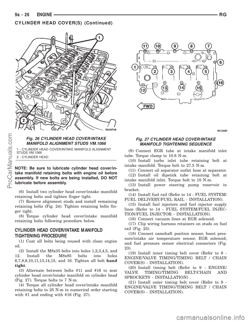
(2) Install the M8x35 bolts into holes 1,2,3,4,5, and
12. Install the M8x85 bolts into holes
6,7,8,9,10,11,13,14,15, and 16. Tighten all bolthand
tight.
(3) Alternate between bolts #11 and #16 to seat
cylinder head cover/intake manifold on cylinder head
(Fig. 27). Torque bolts to 7 N´m.
(4) Torque all cylinder head cover/intake manifold
retaining bolts to 25 N´m in numerical order starting
with #1 and ending with #16 (Fig. 27).(9) Connect EGR tube at intake manifold inlet
tube. Torque clamp to 10.8 N´m.
(10) Install turbo inlet tube retaining bolt at
intake manifold. Torque bolt to 27.5 N´m.
(11) Connect oil separator outlet hose at separator.
(12) Install oil dipstick tube retaining bolt at
intake manifold inlet. Torque bolt to 10 N´m.
(13) Install power steering pump reservoir in
bracket.
(14) Install fuel rail (Refer to 14 - FUEL SYSTEM/
FUEL DELIVERY/FUEL RAIL - INSTALLATION).
(15) Install fuel injectors and fuel injector supply
lines (Refer to 14 - FUEL SYSTEM/FUEL INJEC-
TION/FUEL INJECTOR - INSTALLATION).
(16) Connect vacuum lines at EGR solenoid.
(17) Clip wiring harness retainers on studs on fuel
rail (Fig. 23).
(18) Connect camshaft position sensor, boost pres-
sure/intake air temperature sensor, EGR solenoid,
and fuel pressure sensor electrical connectors (Fig.
23).
(19) Install inner timing belt cover (Refer to 9 -
ENGINE/VALVE TIMING/TIMING BELT / CHAIN
COVER(S) - INSTALLATION).
(20) Install timing belt (Refer to 9 - ENGINE/
VALVE TIMING/TIMING BELT/CHAIN AND
SPROCKETS - INSTALLATION) .
(21) Install outer timing belt cover (Refer to 9 -
ENGINE/VALVE TIMING/TIMING BELT / CHAIN
COVER(S) - INSTALLATION).
Fig. 26 CYLINDER HEAD COVER/INTAKE
MANIFOLD ALIGNMENT STUDS VM.1066
1 - CYLINDER HEAD COVER/INTAKE MANIFOLD ALIGNMENT
STUDS VM.1066
2 - CYLINDER HEAD
Fig. 27 CYLINDER HEAD COVER/INTAKE
MANIFOLD TIGHTENING SEQUENCE
9a - 26 ENGINERG
CYLINDER HEAD COVER(S) (Continued)
ProCarManuals.com
Page 1389 of 2399
(2) Remove front wiper unit (Refer to 8 - ELEC-
TRICAL/WIPERS/WASHERS/WIPER MODULE -
REMOVAL).
(3) Remove air cleaner housing assembly.
(4) Support engine and remove right engine mount
(Refer to 9 - ENGINE/ENGINE MOUNTING/RIGHT
MOUNT - REMOVAL).
(5) Remove outer timing belt cover (Refer to 9 -
ENGINE/VALVE TIMING/TIMING BELT / CHAIN
COVER(S) - REMOVAL).
(6) Remove timing belt (Refer to 9 - ENGINE/
VALVE TIMING/TIMING BELT/CHAIN AND
SPROCKETS - REMOVAL).
(7) Remove inner timing belt cover (Refer to 9 -
ENGINE/VALVE TIMING/TIMING BELT / CHAIN
COVER(S) - REMOVAL).
(8) Remove cylinder head cover/intake manifold
(Refer to 9 - ENGINE/CYLINDER HEAD/CYLIN-
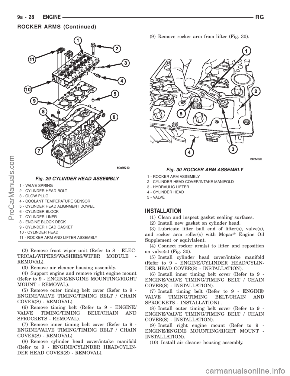
DER HEAD COVER(S) - REMOVAL).(9) Remove rocker arm from lifter (Fig. 30).
INSTALLATION
(1) Clean and inspect gasket sealing surfaces.
(2) Install new gasket on cylinder head.
(3) Lubricate lifter ball end of lifter(s), valve(s),
and rocker arm roller(s) with MopartEngine Oil
Supplement or equivlalent.
(4) Connect rocker arm(s) to lifter and reposition
on valve(s) (Fig. 30).
(5) Install cylinder head cover/intake manifold
(Refer to 9 - ENGINE/CYLINDER HEAD/CYLIN-
DER HEAD COVER(S) - INSTALLATION).
(6) Install inner timing belt cover (Refer to 9 -
ENGINE/VALVE TIMING/TIMING BELT / CHAIN
COVER(S) - INSTALLATION).
(7) Install timing belt (Refer to 9 - ENGINE/
VALVE TIMING/TIMING BELT/CHAIN AND
SPROCKETS - INSTALLATION) .
(8) Install outer timing belt cover (Refer to 9 -
ENGINE/VALVE TIMING/TIMING BELT / CHAIN
COVER(S) - INSTALLATION).
(9) Install right engine mount (Refer to 9 -
ENGINE/ENGINE MOUNTING/RIGHT MOUNT -
INSTALLATION).
(10) Install air cleaner housing assembly.
Fig. 29 CYLINDER HEAD ASSEMBLY
1 - VALVE SPRING
2 - CYLINDER HEAD BOLT
3 - GLOW PLUG
4 - COOLANT TEMPERATURE SENSOR
5 - CYLINDER HEAD ALIGNMENT DOWEL
6 - CYLINDER BLOCK
7 - CYLINDER LINER
8 - ENGINE BLOCK DECK
9 - CYLINDER HEAD GASKET
10 - CYLINDER HEAD
11 - ROCKER ARM AND LIFTER ASSEMBLY
Fig. 30 ROCKER ARM ASSEMBLY
1 - ROCKER ARM ASSEMBLY
2 - CYLINDER HEAD COVER/INTAKE MANIFOLD
3 - HYDRAULIC LIFTER
4 - CYLINDER HEAD
5 - VALVE
9a - 28 ENGINERG
ROCKER ARMS (Continued)
ProCarManuals.com
Page 1390 of 2399
(11) Install front wiper unit (Refer to 8 - ELEC-
TRICAL/WIPERS/WASHERS/WIPER MODULE -
INSTALLATION).
(12) Connect negative battery cable.
HYDRAULIC LIFTERS
DESCRIPTION
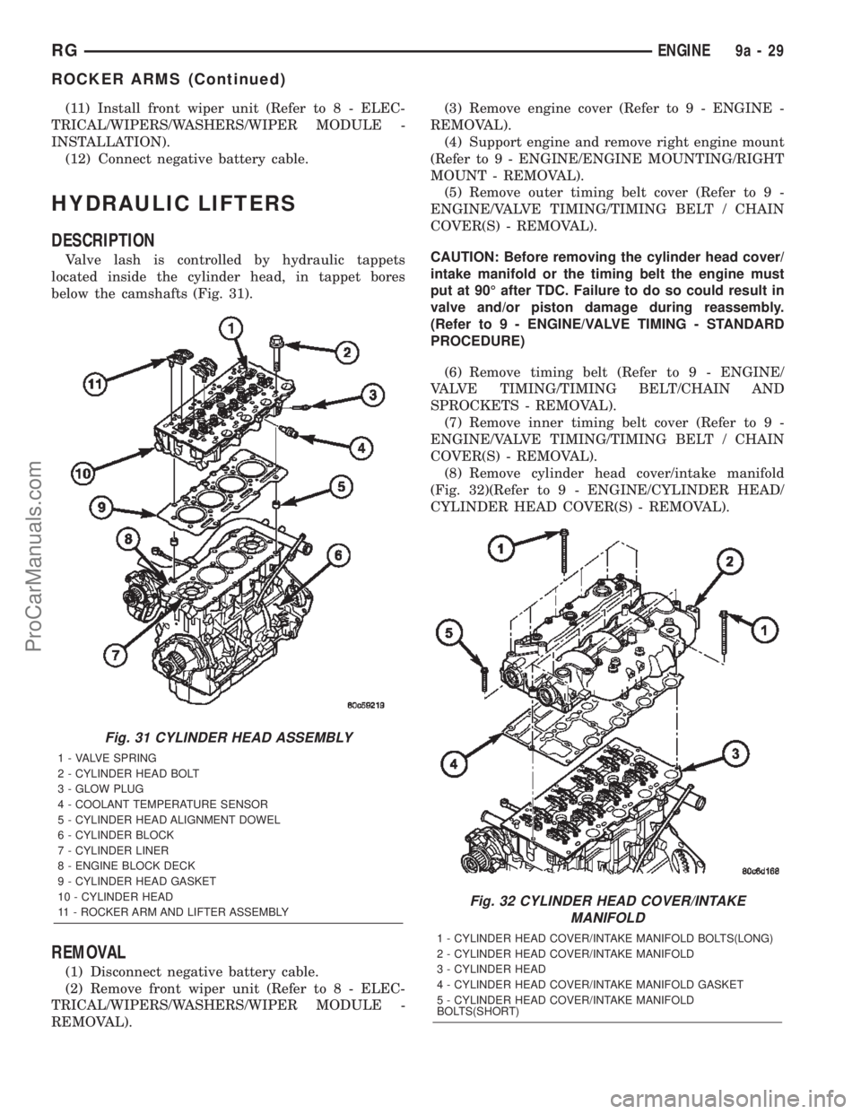
Valve lash is controlled by hydraulic tappets
located inside the cylinder head, in tappet bores
below the camshafts (Fig. 31).
REMOVAL
(1) Disconnect negative battery cable.
(2) Remove front wiper unit (Refer to 8 - ELEC-
TRICAL/WIPERS/WASHERS/WIPER MODULE -
REMOVAL).(3) Remove engine cover (Refer to 9 - ENGINE -
REMOVAL).
(4) Support engine and remove right engine mount
(Refer to 9 - ENGINE/ENGINE MOUNTING/RIGHT
MOUNT - REMOVAL).
(5) Remove outer timing belt cover (Refer to 9 -
ENGINE/VALVE TIMING/TIMING BELT / CHAIN
COVER(S) - REMOVAL).
CAUTION: Before removing the cylinder head cover/
intake manifold or the timing belt the engine must
put at 90É after TDC. Failure to do so could result in
valve and/or piston damage during reassembly.
(Refer to 9 - ENGINE/VALVE TIMING - STANDARD
PROCEDURE)
(6) Remove timing belt (Refer to 9 - ENGINE/
VALVE TIMING/TIMING BELT/CHAIN AND
SPROCKETS - REMOVAL).
(7) Remove inner timing belt cover (Refer to 9 -
ENGINE/VALVE TIMING/TIMING BELT / CHAIN
COVER(S) - REMOVAL).
(8) Remove cylinder head cover/intake manifold
(Fig. 32)(Refer to 9 - ENGINE/CYLINDER HEAD/
CYLINDER HEAD COVER(S) - REMOVAL).
Fig. 31 CYLINDER HEAD ASSEMBLY
1 - VALVE SPRING
2 - CYLINDER HEAD BOLT
3 - GLOW PLUG
4 - COOLANT TEMPERATURE SENSOR
5 - CYLINDER HEAD ALIGNMENT DOWEL
6 - CYLINDER BLOCK
7 - CYLINDER LINER
8 - ENGINE BLOCK DECK
9 - CYLINDER HEAD GASKET
10 - CYLINDER HEAD
11 - ROCKER ARM AND LIFTER ASSEMBLY
Fig. 32 CYLINDER HEAD COVER/INTAKE
MANIFOLD
1 - CYLINDER HEAD COVER/INTAKE MANIFOLD BOLTS(LONG)
2 - CYLINDER HEAD COVER/INTAKE MANIFOLD
3 - CYLINDER HEAD
4 - CYLINDER HEAD COVER/INTAKE MANIFOLD GASKET
5 - CYLINDER HEAD COVER/INTAKE MANIFOLD
BOLTS(SHORT)
RGENGINE9a-29
ROCKER ARMS (Continued)
ProCarManuals.com
Page 1407 of 2399
CRANKSHAFT OIL SEAL -
REAR
REMOVAL
This must be done with either the engine or trans-
mission removed from vehicle.
(1) Remove flywheel assembly.
(2) Pry out old crankshaft oil seal.
INSTALLATION
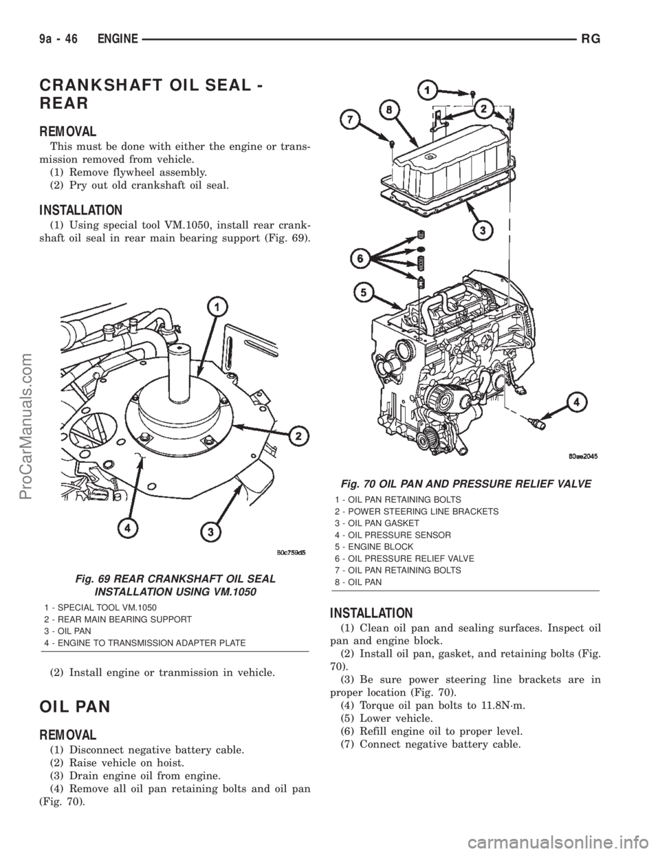
(1) Using special tool VM.1050, install rear crank-
shaft oil seal in rear main bearing support (Fig. 69).
(2) Install engine or tranmission in vehicle.
OIL PAN
REMOVAL
(1) Disconnect negative battery cable.
(2) Raise vehicle on hoist.
(3) Drain engine oil from engine.
(4) Remove all oil pan retaining bolts and oil pan
(Fig. 70).
INSTALLATION
(1) Clean oil pan and sealing surfaces. Inspect oil
pan and engine block.
(2) Install oil pan, gasket, and retaining bolts (Fig.
70).
(3) Be sure power steering line brackets are in
proper location (Fig. 70).
(4) Torque oil pan bolts to 11.8N´m.
(5) Lower vehicle.
(6) Refill engine oil to proper level.
(7) Connect negative battery cable.
Fig. 69 REAR CRANKSHAFT OIL SEAL
INSTALLATION USING VM.1050
1 - SPECIAL TOOL VM.1050
2 - REAR MAIN BEARING SUPPORT
3 - OIL PAN
4 - ENGINE TO TRANSMISSION ADAPTER PLATE
Fig. 70 OIL PAN AND PRESSURE RELIEF VALVE
1 - OIL PAN RETAINING BOLTS
2 - POWER STEERING LINE BRACKETS
3 - OIL PAN GASKET
4 - OIL PRESSURE SENSOR
5 - ENGINE BLOCK
6 - OIL PRESSURE RELIEF VALVE
7 - OIL PAN RETAINING BOLTS
8 - OIL PAN
9a - 46 ENGINERG
ProCarManuals.com
Page 1409 of 2399
(3) Install oil pump retaining bolts (Fig. 71).
Torque bolts to 10.8N´m.
(4) Install crankshaft sprocket (Fig. 71). Torque
bolts to 10.8N´m.
(5) Install front engine cover (Refer to 9 -
ENGINE/ENGINE BLOCK/ENGINE COVER -
INSTALLATION).
(6) Install timing belt inner cover (Refer to 9 -
ENGINE/VALVE TIMING/TIMING BELT / CHAIN
COVER(S) - INSTALLATION).
(7) Install timing belt (Refer to 9 - ENGINE/
VALVE TIMING/TIMING BELT/CHAIN AND
SPROCKETS - INSTALLATION) .
(8) Install timing belt outer cover (Refer to 9 -
ENGINE/VALVE TIMING/TIMING BELT / CHAIN
COVER(S) - INSTALLATION).
(9) Install accessory drive belt (Refer to 7 - COOL-
ING/ACCESSORY DRIVE/DRIVE BELTS - INSTAL-
LATION).
(10) Install power steering belt (Refer to 7 -
COOLING/ACCESSORY DRIVE/DRIVE BELTS -
INSTALLATION).
(11) Connect negative battery cable.
INSTALLATION
(1) Lubricate o-ring on oil pump pickup tube with
engine oil.
(2) Install pickup tube in engine block and install
retaining bolt (Fig. 72). Torque bolt to 32.4N´m.
(3) Install oil pan (Refer to 9 - ENGINE/LUBRI-
CATION/OIL PAN - INSTALLATION).
(4) Refill engine oil to proper level.
(5) Connect negative battery cable.
OIL PRESSURE SENSOR/
SWITCH
DESCRIPTION
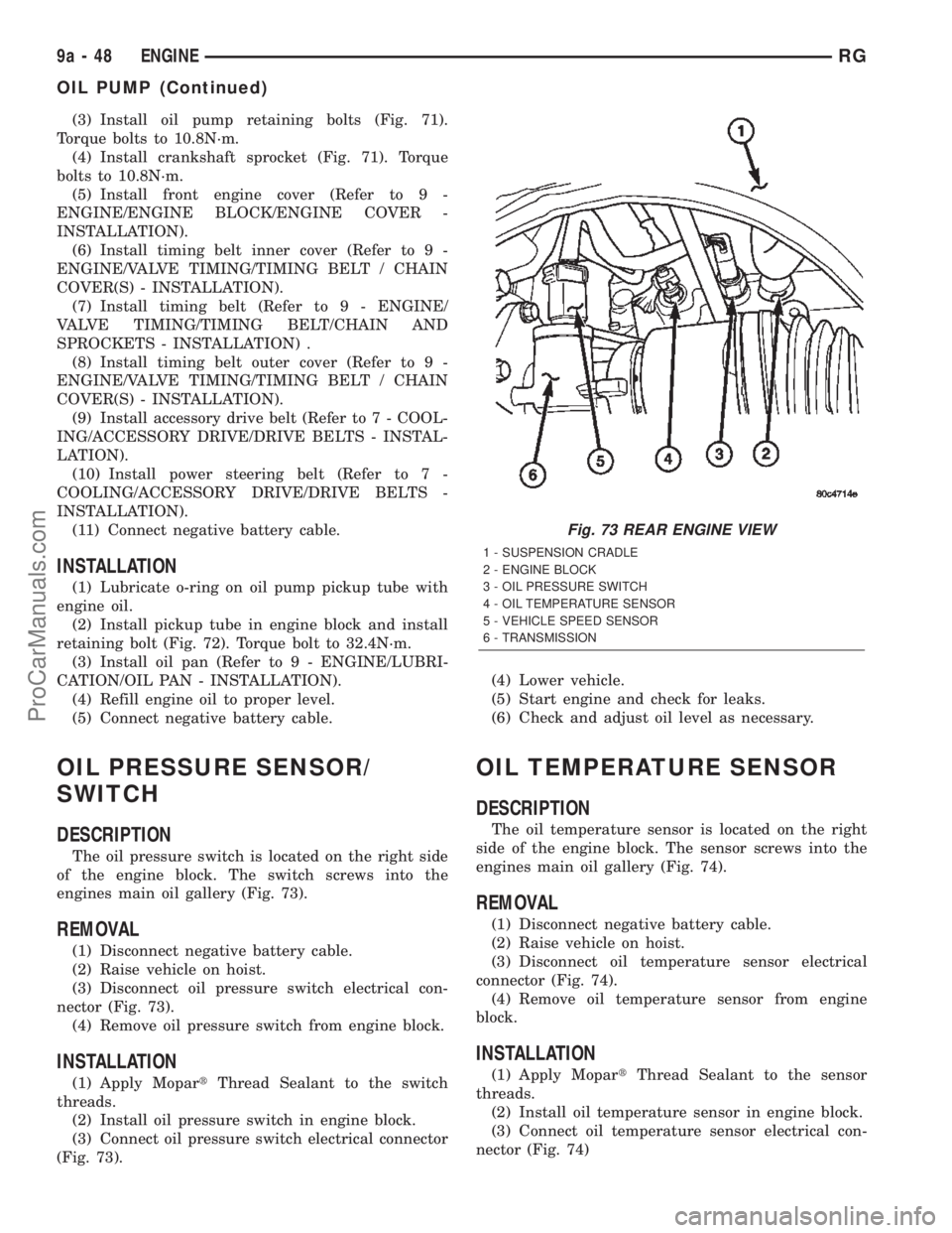
The oil pressure switch is located on the right side
of the engine block. The switch screws into the
engines main oil gallery (Fig. 73).
REMOVAL
(1) Disconnect negative battery cable.
(2) Raise vehicle on hoist.
(3) Disconnect oil pressure switch electrical con-
nector (Fig. 73).
(4) Remove oil pressure switch from engine block.
INSTALLATION
(1) Apply MopartThread Sealant to the switch
threads.
(2) Install oil pressure switch in engine block.
(3) Connect oil pressure switch electrical connector
(Fig. 73).(4) Lower vehicle.
(5) Start engine and check for leaks.
(6) Check and adjust oil level as necessary.
OIL TEMPERATURE SENSOR
DESCRIPTION
The oil temperature sensor is located on the right
side of the engine block. The sensor screws into the
engines main oil gallery (Fig. 74).
REMOVAL
(1) Disconnect negative battery cable.
(2) Raise vehicle on hoist.
(3) Disconnect oil temperature sensor electrical
connector (Fig. 74).
(4) Remove oil temperature sensor from engine
block.
INSTALLATION
(1) Apply MopartThread Sealant to the sensor
threads.
(2) Install oil temperature sensor in engine block.
(3) Connect oil temperature sensor electrical con-
nector (Fig. 74)
Fig. 73 REAR ENGINE VIEW
1 - SUSPENSION CRADLE
2 - ENGINE BLOCK
3 - OIL PRESSURE SWITCH
4 - OIL TEMPERATURE SENSOR
5 - VEHICLE SPEED SENSOR
6 - TRANSMISSION
9a - 48 ENGINERG
OIL PUMP (Continued)
ProCarManuals.com
Page 1410 of 2399
(4) Lower vehicle.
(5) Start engine and check for leaks.
(6) Check and adjust oil level as necessary.
OIL PRESSURE RELIEF VALVE
DESCRIPTION
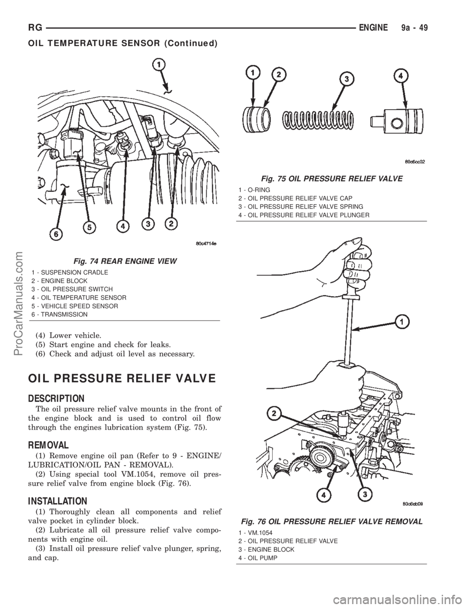
The oil pressure relief valve mounts in the front of
the engine block and is used to control oil flow
through the engines lubrication system (Fig. 75).
REMOVAL
(1) Remove engine oil pan (Refer to 9 - ENGINE/
LUBRICATION/OIL PAN - REMOVAL).
(2) Using special tool VM.1054, remove oil pres-
sure relief valve from engine block (Fig. 76).
INSTALLATION
(1) Thoroughly clean all components and relief
valve pocket in cylinder block.
(2) Lubricate all oil pressure relief valve compo-
nents with engine oil.
(3) Install oil pressure relief valve plunger, spring,
and cap.
Fig. 74 REAR ENGINE VIEW
1 - SUSPENSION CRADLE
2 - ENGINE BLOCK
3 - OIL PRESSURE SWITCH
4 - OIL TEMPERATURE SENSOR
5 - VEHICLE SPEED SENSOR
6 - TRANSMISSION
Fig. 75 OIL PRESSURE RELIEF VALVE
1 - O-RING
2 - OIL PRESSURE RELIEF VALVE CAP
3 - OIL PRESSURE RELIEF VALVE SPRING
4 - OIL PRESSURE RELIEF VALVE PLUNGER
Fig. 76 OIL PRESSURE RELIEF VALVE REMOVAL
1 - VM.1054
2 - OIL PRESSURE RELIEF VALVE
3 - ENGINE BLOCK
4 - OIL PUMP
RGENGINE9a-49
OIL TEMPERATURE SENSOR (Continued)
ProCarManuals.com
Page 1426 of 2399

(1) Disconnect and remove the upstream (before
catalytic converter) oxygen sensor. (Refer to 14 -
FUEL SYSTEM/FUEL INJECTION/O2 SENSOR -
REMOVAL)
(2) Install the Exhaust Back Pressure Fitting
Adaptor CH8519.
(3) Connect the Low Pressure Sensor (15 psi)
CH7063 to the back pressure fitting.
(4) Following the PEP module instruction manual,
connect all required cables to the DRB IIItand PEP
module. Select the available menu options on the
DRBIIItdisplay screen for using the digital pressure
gauge function.
(5) Apply the park brake and start the engine.
(6) With transmission in Park or Neutral, raise
engine speed to 2000 RPM. Monitor the pressure
readings on the DRBIIIt. Back pressure should not
exceed specified limit. Refer to specification in table
below EXHAUST BACK PRESSURE LIMITS .
NOTE: For applications with dual catalytic convert-
ers, repeat test on opposite converter using the
previous steps.
(7) If pressure exceeds maximum limits, inspect
exhaust system for restricted component. For further
catalytic converter inspection procedures, (Refer to 11
- EXHAUST SYSTEM/CATALYTIC CONVERTER -
INSPECTION). Replace component(s) as necessary.
EXHAUST BACK PRESSURE LIMITS
Exhaust Back Pressure Limit (Max)
Vehicle in Park/Neutral
(no load) RPM3.45 Kpa (0.5 psi)
INSPECTION
Inspect the exhaust pipes, catalytic converters,
muffler, and resonators for cracked joints, broken
welds and corrosion damage that would result in a
leaking exhaust system. Inspect the clamps, support
brackets, and insulators for cracks and corrosion
damage.
NOTE: Slip joint band clamps are spot welded to
exhaust system. If a band clamp must be replaced,
the spot weld must be ground off.
ADJUSTMENTS
A misaligned exhaust system is usually indicated
by a vibration, rattling noise, or binding of exhaust
system components. These noises are sometimes hard
to distinguish from other chassis noises. Inspect
exhaust system for broken, damaged or loose compo-
nents such as; clamps, heat shields, isolators, andhanger brackets. Replace or tighten as necessary. It
is important that exhaust system clearances and
alignment be maintained.
Perform the following procedures to align the
exhaust system:
(1) Loosen band clamp at catalytic converter pipe
to muffler/resonator assembly.
(2) Align the exhaust system by inserting pipe
inward or outward until specification is achieved as
shown in (Fig. 2).
(3) Tighten band clamp to 54 N´m (40 ft. lbs.).
SPECIFICATIONS
TORQUE
DESCRIPTION N´mFt.
Lbs.In.
Lbs.
Band Clamp 54 40 Ð
Cross-over PipeÐFastener 41 30 Ð
Exhaust Manifold FlangeÐFastener 37 Ð 325
Heat Shield (Muffler)ÐFastener 2.6 Ð 23
Heat Shield (Toe Board)ÐFastener 2.6 Ð 23
Heat Shield (Resonator Pipe)Ð
Fastener2.6 Ð 23
Insulator Mounting BracketÐBolts 28 Ð 250
Fig. 2 Exhaust System Alignment
1 - HANGER BRACKET TO BODY
2 - ISOLATOR
3 - HANGER - MUFFLER/RESONATOR SUPPORT
4-6mm(0.25 in.)
RSEXHAUST SYSTEM11-3
EXHAUST SYSTEM (Continued)
ProCarManuals.com