2002 CHRYSLER CARAVAN air condition
[x] Cancel search: air conditionPage 2351 of 2399
INSTALLATION
INSTALLATION - REAR HEATER LINES
(1) Install line into underbody straps.
(2) Install line into front hose and install hose
clamp.
(3) Connect quick fitting at rear of line.
(4) Lower vehicle.
(5) Fill cooling system (Refer to 7 - COOLING -
STANDARD PROCEDURE).
INSTALLATION - REAR AIR CONDITIONING
LINES
(1) Before installation, replace all O-rings and gas-
kets. Coat all sealing surfaces with approved wax-
free refrigerant oil.
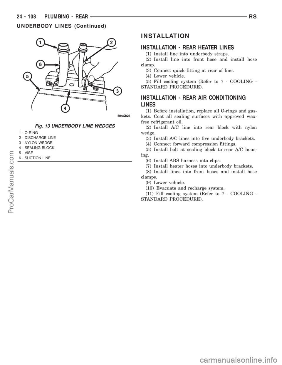
(2) Install A/C line into rear block with nylon
wedge.
(3) Install A/C lines into five underbody brackets.
(4) Connect forward compression fittings.
(5) Install bolt at sealing block to rear A/C hous-
ing.
(6) Install ABS harness into clips.
(7) Install heater hoses into underbody brackets.
(8) Install lines into front hoses and install hose
clamps.
(9) Lower vehicle.
(10) Evacuate and recharge system.
(11) Fill cooling system (Refer to 7 - COOLING -
STANDARD PROCEDURE).
Fig. 13 UNDERBODY LINE WEDGES
1 - O-RING
2 - DISCHARGE LINE
3 - NYLON WEDGE
4 - SEALING BLOCK
5 - VISE
6 - SUCTION LINE
24 - 108 PLUMBING - REARRS
UNDERBODY LINES (Continued)
ProCarManuals.com
Page 2353 of 2399
DIAGNOSIS AND TESTING - DIESEL
SUPPLEMENTAL HEATER - DCHA
The following table lists possible fault symptoms of
diesel fueled heaters.
SYMPTOM POSSIBLE CAUSES
Smell of diesel fuel Check heater system integration in vehicle's fuel system. Check fuel
lines for leakage, kinks or obstructions. If OK, Inspect the inlet muffler,
drain as necessary. Re-test the unit and re-inspect. Inspect the
exhaust tube and heater unit for the presence of external fuel. If a
volume is observed on the unit or in the exhaust tube or after draining
and testing. Remove heater unit from vehicle and repair or replace
components as required.
Heater does not achieve full load
operation.Check heater operation with DRB-III and replace components as
required.
Continuous white smoke from heater
exhaust during combustion operation.Check heater operation with DRB-III and replace components as
required. White smoke is typical in extreme weather conditions.
Heater can not be switched off. Check heater operation with DRB-III and replace components as
required.
Heater does not operate. Diagnosis cabin heater ECU using the DRB-III and the procedures
listed in Vehicle Performance under Cabin Heater Diagnosis in Group
18.
Loss of coolant (Leakage) or heater
develops smoke during combustion
operation and exhaust has an
extremely sweet smell.Inspect coolant hoses for leakage, kinks or loose hose connection.
Inspect the exhaust tube assembly for continuous flow, if OK there is
an internal heater leak and unit should be inspected and components
should be replaced as required.
Loss of fuel (dripping). Check heater system integration in vehicles fuel system. Check fuel
line connection for leakage. If OK there is an internal leak and unit
should be inspected and replaced as required.
EXHAUST TUBE
REMOVAL
WARNING: THERE IS A POTENTIAL DANGER OF
SKIN BURNS AS THE HEATER AND ITS COMPO-
NENTS MAY BE VERY HOT. MAKE SURE THE
HEATER IS ALLOWED TO COOL DOWN BEFORE
ANY SERVICE WORK IS ATTEMPTED.
WARNING: THERE IS A POTENTIAL DANGER OF
SKIN BURNS AS THE EXHAUST SYSTEM MAY BE
VERY HOT. MAKE SURE THE EXHAUST SYSTEM IS
ALLOWED TO COOL DOWN BEFORE ANY SERVICE
WORK IS ATTEMPTED ON THE CABIN HEATER.
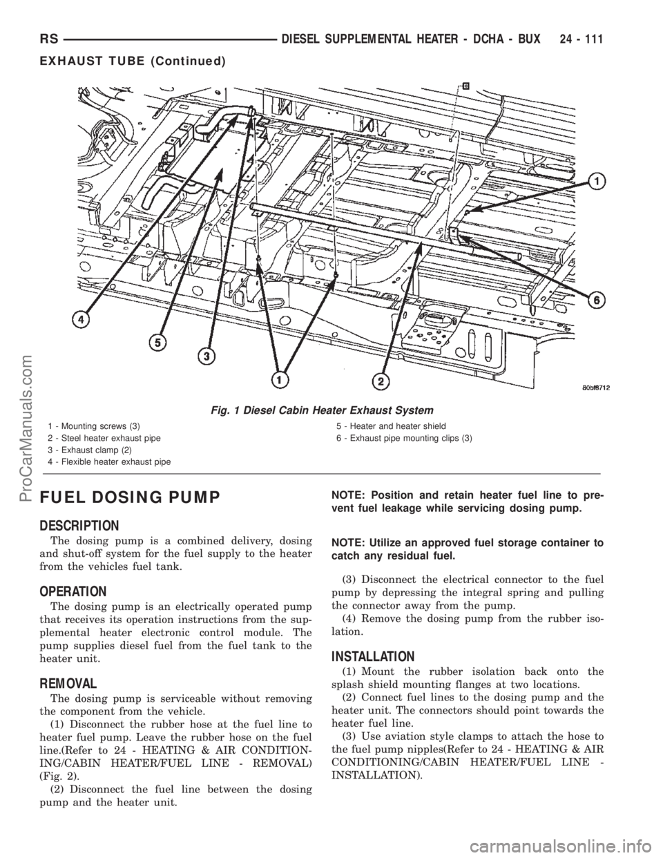
(1) Elevate vehicle on a lift taking note of the
exhaust tube flexible section.
(2) Remove the exhaust clamp at the flexible pipe
and steel pipe connection (Fig. 1).
(3) Remove the clamp at the flexible pipe connec-
tion and the heater unit housing (if required).(4) Remove the three screws holding the exhaust
pipe to the body.
(5) Remove the steel exhaust pipe from the vehi-
cle.
(6) Remove the flexible exhaust pipe from the
vehicle (if required).
INSTALLATION
(1) Install the flexible exhaust pipe to the heater
unit. Tighten mounting clamp.
(2) Position the steel exhaust pipe to the flexible
exhaust and install and tighten the mounting clamp.
(3) Install the three exhaust pipe screws, adjust
pipe placement as needed and tighten the screws.
(4) Install the clamp to connect the steel exhaust
pipe to the flexible exhaust pipe and tighten clamp.
(5) Check exhaust pipe exhaust end placement and
make any final adjustments.
(6) Lower vehicle from lift.
24 - 110 DIESEL SUPPLEMENTAL HEATER - DCHA - BUXRS
DIESEL SUPPLEMENTAL HEATER - DCHA - BUX (Continued)
ProCarManuals.com
Page 2354 of 2399
FUEL DOSING PUMP
DESCRIPTION
The dosing pump is a combined delivery, dosing
and shut-off system for the fuel supply to the heater
from the vehicles fuel tank.
OPERATION
The dosing pump is an electrically operated pump
that receives its operation instructions from the sup-
plemental heater electronic control module. The
pump supplies diesel fuel from the fuel tank to the
heater unit.
REMOVAL
The dosing pump is serviceable without removing
the component from the vehicle.
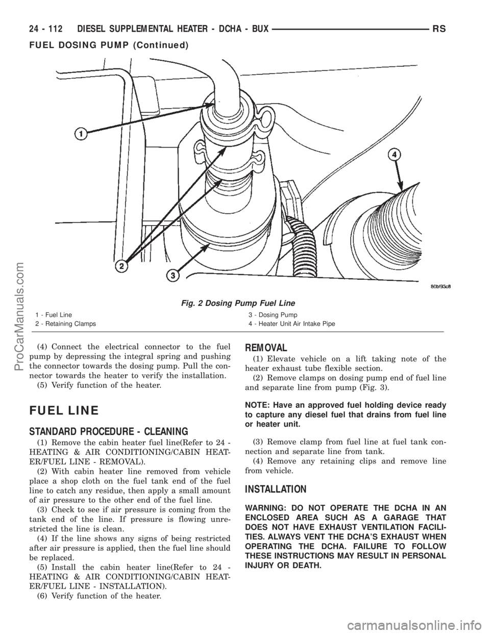
(1) Disconnect the rubber hose at the fuel line to
heater fuel pump. Leave the rubber hose on the fuel
line.(Refer to 24 - HEATING & AIR CONDITION-
ING/CABIN HEATER/FUEL LINE - REMOVAL)
(Fig. 2).
(2) Disconnect the fuel line between the dosing
pump and the heater unit.NOTE: Position and retain heater fuel line to pre-
vent fuel leakage while servicing dosing pump.
NOTE: Utilize an approved fuel storage container to
catch any residual fuel.
(3) Disconnect the electrical connector to the fuel
pump by depressing the integral spring and pulling
the connector away from the pump.
(4) Remove the dosing pump from the rubber iso-
lation.
INSTALLATION
(1) Mount the rubber isolation back onto the
splash shield mounting flanges at two locations.
(2) Connect fuel lines to the dosing pump and the
heater unit. The connectors should point towards the
heater fuel line.
(3) Use aviation style clamps to attach the hose to
the fuel pump nipples(Refer to 24 - HEATING & AIR
CONDITIONING/CABIN HEATER/FUEL LINE -
INSTALLATION).
Fig. 1 Diesel Cabin Heater Exhaust System
1 - Mounting screws (3)
2 - Steel heater exhaust pipe
3 - Exhaust clamp (2)
4 - Flexible heater exhaust pipe5 - Heater and heater shield
6 - Exhaust pipe mounting clips (3)
RSDIESEL SUPPLEMENTAL HEATER - DCHA - BUX24 - 111
EXHAUST TUBE (Continued)
ProCarManuals.com
Page 2355 of 2399
(4) Connect the electrical connector to the fuel
pump by depressing the integral spring and pushing
the connector towards the dosing pump. Pull the con-
nector towards the heater to verify the installation.
(5) Verify function of the heater.
FUEL LINE
STANDARD PROCEDURE - CLEANING
(1) Remove the cabin heater fuel line(Refer to 24 -
HEATING & AIR CONDITIONING/CABIN HEAT-
ER/FUEL LINE - REMOVAL).
(2) With cabin heater line removed from vehicle
place a shop cloth on the fuel tank end of the fuel
line to catch any residue, then apply a small amount
of air pressure to the other end of the fuel line.
(3) Check to see if air pressure is coming from the
tank end of the line. If pressure is flowing unre-
stricted the line is clean.
(4) If the line shows any signs of being restricted
after air pressure is applied, then the fuel line should
be replaced.
(5) Install the cabin heater line(Refer to 24 -
HEATING & AIR CONDITIONING/CABIN HEAT-
ER/FUEL LINE - INSTALLATION).
(6) Verify function of the heater.
REMOVAL
(1) Elevate vehicle on a lift taking note of the
heater exhaust tube flexible section.
(2) Remove clamps on dosing pump end of fuel line
and separate line from pump (Fig. 3).
NOTE: Have an approved fuel holding device ready
to capture any diesel fuel that drains from fuel line
or heater unit.
(3) Remove clamp from fuel line at fuel tank con-
nection and separate line from tank.
(4) Remove any retaining clips and remove line
from vehicle.
INSTALLATION
WARNING: DO NOT OPERATE THE DCHA IN AN
ENCLOSED AREA SUCH AS A GARAGE THAT
DOES NOT HAVE EXHAUST VENTILATION FACILI-
TIES. ALWAYS VENT THE DCHA'S EXHAUST WHEN
OPERATING THE DCHA. FAILURE TO FOLLOW
THESE INSTRUCTIONS MAY RESULT IN PERSONAL
INJURY OR DEATH.
Fig. 2 Dosing Pump Fuel Line
1 - Fuel Line
2 - Retaining Clamps3 - Dosing Pump
4 - Heater Unit Air Intake Pipe
24 - 112 DIESEL SUPPLEMENTAL HEATER - DCHA - BUXRS
FUEL DOSING PUMP (Continued)
ProCarManuals.com
Page 2357 of 2399
(7) With the DRBIIItin Cabin Heater, select Sys-
tem Tests and Dosing Pump Prime. Allow the Dosing
Pump to run for the full 45 second cycle time. When
the 45 second cycle is complete, press Page Back on
the DRBIIItkey pad to exit the Dosing Pump Prime.
The Dosing Pump priming procedure is now com-
plete.
HEATER UNIT
REMOVAL
WARNING: ALLOW THE DCHA TO COOL BEFORE
PERFORMING A COMPONENT INSPECTION/REPAIR
OR REPLACEMENT. FAILURE TO FOLLOW THESE
INSTRUCTIONS MAY RESULT IN PERSONAL
INJURY.
WARNING: ALLOW THE EXHAUST SYSTEM TO
COOL BEFORE PERFORMING A COMPONENT
INSPECTION/REPAIR OR REPLACEMENT. FAILURE
TO FOLLOW THESE INSTRUCTION MAY RESULT IN
PERSONAL INJURY.
(1) Elevate the vehicle on a hoist/lift taking note of
heater exhaust tube flexible section.
(2) Drain cooling system(Refer to 7 - COOLING -
STANDARD PROCEDURE).
(3) Carefully open one hose to the underbody tube
assembly and drain the remaining coolant. A salvage
hose is a good idea to control the residual coolant, as
flow will occur from both the heater and the hose and
tube assemblies.
(4) Remove the second hose from the underbody
hose and tube assembly.
(5) Loosen the hose and tube assembly from the
toe-board cross member at two locations.
(6) Disconnect the electrical connector from the
body harness near the toe board cross member and
rail.
(7) Remove the wiring harness from the toe board
cross member(Refer to 24 - HEATING & AIR CON-
DITIONING/CABIN HEATER/HEATER UNIT -
REMOVAL).
(8) Open the fuel fill cap. Disconnect the rubber
fuel hose between the body tube assembly and the
fuel pump nipple at the body tube joint. A minimal
amount of fuel may flow from the open port.
NOTE: Utilize an approved fuel storage container to
catch any residual fuel.
(9) Loosen the two M8 fasteners at the rail. Take
care to notice that the exhaust tube bracket tab is on
top of the heater bracket.(10) Remove the heater exhaust tube flex section
from the exhaust tube by loosening the M6 bolt of
the clamp assembly. Remove the hose from the
exhaust tube. Removal of the rail tube assembly may
aid in this service operation.(Refer to 24 - HEATING
& AIR CONDITIONING/CABIN HEATER/EXHAUST
TUBE - REMOVAL).
(11) Remove seat hex nut at the heater mounting
flange to cross member.
(12) Loosen the remaining M6 and M8 fasteners
which mount the exhaust tube assembly to the vehi-
cle.
(a) Install a suitable cabin heater support device
under the cabin heater and secure the cabin heater
to the device.
(13) Loosen the remaining three M6 fasteners to
the cross members.
(14) Remove the loosened fasteners that support
the heater while supporting the weight of the heater.
(15) Swing the unit mounting bracket from
between the exhaust bracket and rail mounting loca-
tion. Drain any residual coolant from the heater unit.
(16) Lower the cabin heater and remove from the
supporting device and place on a suitable work area.
INSTALLATION
(1) Install the unit mounting bracket between the
exhaust bracket and the rail mounting location.
(2) Install the fasteners that support the heater
while supporting the weight of the heater.
(3) Install the three M6 fasteners to the cross
members. Tighten the M6 fasteners to 7 Nm (5 ft.
lbs.).
(4) Tighten the remaining M6 fasteners to 7 Nm (5
ft. lbs.) and the M8 fasteners to 23 Nm (17 ft. lbs.)
which mount the exhaust tube assembly to the vehi-
cle.
(5) Install the seat hex nut at the heater mounting
flange to the cross members. Tighten to 60 Nm (44 ft.
lbs.)
(6) Install the heater exhaust tube flex section to
the exhaust tube by tightening the M6 bolt of the
clamp assembly. Install the hose to the exhaust tube.
(7) Tighten the two M8 fasteners at the rail to 23
Nm (17 ft. lbs.). Taking care so that the exhaust tube
bracket tab is on the top of the heater bracket.
(8) Install the wiring harness(Refer to 24 - HEAT-
ING & AIR CONDITIONING/CABIN HEATER/
HEATER UNIT - INSTALLATION).
(9) Tighten the hose and tube assembly to the toe-
board cross member at two locations.
(10) Install the second hose to the underbody hose
and tube assembly.
(11) Connect the rubber fuel hose between the
body tube assembly and the fuel pump nipple at the
body tube joint. Close the fuel fill cap.
24 - 114 DIESEL SUPPLEMENTAL HEATER - DCHA - BUXRS
FUEL LINE (Continued)
ProCarManuals.com
Page 2358 of 2399
(12) Remove the heater unit support device from
under the vehicle.
(13) Lower vehicle from lift.
(14) Refill cooling system(Refer to 7 - COOLING -
STANDARD PROCEDURE).
(15) Verify function of the cabin heater.
SUPPLEMENTAL DIESEL
HEATER WIRING
REMOVAL
(1) Elevate vehicle on a lift taking note of the
exhaust tube flexible section.
(2) Unplug connector from vehicle wiring harness
to cabin heater harness.
(3) Unplug connector from cabin heater harness to
dosing pump connector.
(4) Unplug two connectors from cabin heater har-
ness to cabin heater controller connectors.
(5) Remove two wiring harness connectors from
underbody.
(6) Remove two wiring harness connectors from
cabin heater shield.
(7) Carefully route the cabin heater harness to the
left side between the cabin heater unit and the cabin
heater shield.
INSTALLATION
(1) Carefully route the cabin heater harness from
the left side of the cabin heater between the cabin
heater unit and the cabin heater shield.
(2) Install the two wiring harness retaining con-
nectors to the cabin heater shield.
(3) Route the wiring harness along the underside
of the vehicle and install the two wiring harness
retaining connectors.
(4) Plug the two connectors from the cabin heater
harness to the cabin heater controller.
(5) Plug the connector to the cabin heater harness
to the dosing pump connector.
(6) Plug the connector from the vehicle wiring har-
ness to the cabin heater harness.
(7) Lower the vehicle.
(8) Verify function of the cabin heater.
AIR INTAKE PIPE
REMOVAL
NOTE: Heater air intake tube is part of an assembly
that includes the heater cooling intake and return
pipes. If heater air intake tube requires removal or
replacement the entire assembly will require remov-
al/replacement.
(1) Drain cooling system(Refer to 7 - COOLING -
STANDARD PROCEDURE).
(2) Remove clamps from the heater tubes at the
lower heater port and the lower EGR connector
which are located under the hood.
(3) Remove the retaining clamp at the heater air
intake muffler connection(Refer to 24 - HEATING &
AIR CONDITIONING/CABIN HEATER/INLET
MUFFLER - REMOVAL).
(4) Remove the clamp at the flexible tube to steel
tube connection (Fig. 4).
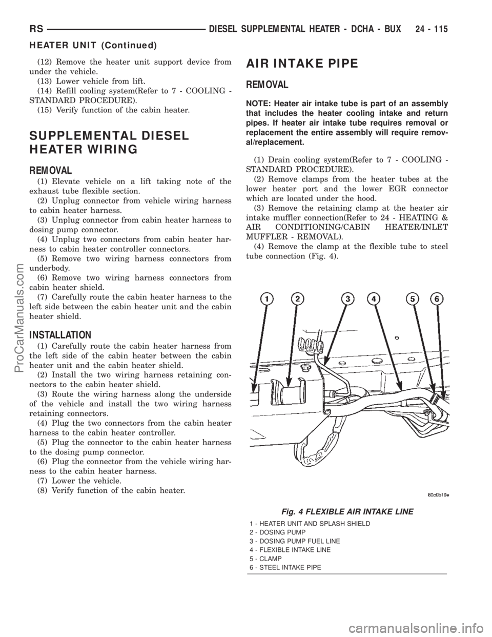
Fig. 4 FLEXIBLE AIR INTAKE LINE
1 - HEATER UNIT AND SPLASH SHIELD
2 - DOSING PUMP
3 - DOSING PUMP FUEL LINE
4 - FLEXIBLE INTAKE LINE
5 - CLAMP
6 - STEEL INTAKE PIPE
RSDIESEL SUPPLEMENTAL HEATER - DCHA - BUX24 - 115
HEATER UNIT (Continued)
ProCarManuals.com
Page 2360 of 2399
EMISSIONS CONTROL
TABLE OF CONTENTS
page page
EMISSIONS CONTROL
DESCRIPTION
DESCRIPTION - VEHICLE EMISSION
CONTROL INFORMATION LABEL..........1
DESCRIPTION - TRIP DEFINITION.........1
DESCRIPTION - MONITORED COMPONENT . 1
OPERATION - NON-MONITORED CIRCUITS . . 5
DESCRIPTION - MONITORED SYSTEMS....6DESCRIPTION - HIGH AND LOW LIMITS....9
OPERATION
OPERATION - SYSTEM..................9
DRB IIITSTATE DISPLAY TEST MODE.....10
EVAPORATIVE EMISSIONS................11
EXHAUST GAS RECIRCULATION...........20
ON-BOARD DIAGNOSTICS................24
EMISSIONS CONTROL
DESCRIPTION
DESCRIPTION - VEHICLE EMISSION CONTROL
INFORMATION LABEL
All models have a Vehicle Emission Control Infor-
mation (VECI) Label. Chrysler permanently attaches
the label in the engine compartment. It cannot be
removed without defacing information and destroying
the label.
The label contains the vehicle's emission specifica-
tions and vacuum hose routings. All hoses must be
connected and routed according to the label.
DESCRIPTION - TRIP DEFINITION
A ªTripº means vehicle operation (following an
engine-off period) of duration and driving mode such
that all components and systems are monitored at
least once by the diagnostic system. The monitors
must successfully pass before the PCM can verify
that a previously malfunctioning component is meet-
ing the normal operating conditions of that compo-
nent. For misfire or fuel system malfunction, the
MIL may be extinguished if the fault does not recur
when monitored during three subsequent sequential
driving cycles in which conditions are similar to
those under which the malfunction was first deter-
mined.
Anytime the MIL is illuminated, a DTC is stored.
The DTC can self erase only after the MIL has been
extinguished. Once the MIL is extinguished, the
PCM must pass the diagnostic test for the most
recent DTC for 40 warm-up cycles (80 warm-up
cycles for the Fuel System Monitor and the Misfire
Monitor). A warm-up cycle can best be described by
the following:
²The engine must be running²A rise of 40ÉF in engine temperature must occur
from the time when the engine was started
²
Engine coolant temperature must crossover 160ÉF
²A ªdriving cycleº that consists of engine start up
and engine shut off.
Once the above conditions occur, the PCM is con-
sidered to have passed a warm-up cycle. Due to the
conditions required to extinguish the MIL and erase
the DTC, it is most important that after a repair has
been made, all DTC's be erased and the repair veri-
fied by running 1±good trip.
DESCRIPTION - MONITORED COMPONENT
There are several components that will affect vehi-
cle emissions if they malfunction. If one of these com-
ponents malfunctions the Malfunction Indicator
Lamp (Check Engine) will illuminate.
Some of the component monitors are checking for
proper operation of the part. Electrically operated
components now have input (rationality) and output
(functionality) checks. Previously, a component like
the Throttle Position sensor (TPS) was checked by
the PCM for an open or shorted circuit. If one of
these conditions occurred, a DTC was set. Now there
is a check to ensure that the component is working.
This is done by watching for a TPS indication of a
greater or lesser throttle opening than MAP and
engine rpm indicate. In the case of the TPS, if engine
vacuum is low and engine rpm is 1600 or greater and
the TPS indicates a small throttle opening, a DTC
will be set. The same applies to low vacuum and
1600 rpm.
Any component that has an associated limp in will
set a fault after 1 trip with the malfunction present.
Refer to the Diagnostic Trouble Codes Description
Charts (Refer to 8 - ELECTRICAL/ELECTRONIC
CONTROL MODULES/POWERTRAIN CONTROL
MODULE - DESCRIPTION) and the appropriate
Powertrain Diagnostic Procedure Manual for diag-
nostic procedures.
RSEMISSIONS CONTROL25-1
ProCarManuals.com
Page 2361 of 2399
The following is a list of the monitored compo-
nents:
²Comprehensive Components
²Oxygen Sensor Monitor
²Oxygen Sensor Heater Monitor
²Catalyst Monitor
COMPREHENSIVE COMPONENTS
Along with the major monitors, OBD II requires
that the diagnostic system monitor any component
that could affect emissions levels. In many cases,
these components were being tested under OBD I.
The OBD I requirements focused mainly on testing
emissions-related components for electrical opens and
shorts.
However, OBD II also requires that inputs from
powertrain components to the PCM be tested for
rationality, and that outputs to powertrain compo-
nents from the PCM be tested forfunctionality.
Methods for monitoring the various Comprehensive
Component monitoring include:
(1) Circuit Continuity
²Open
²Shorted high
²Shorted to ground
(2) Rationality or Proper Functioning
²Inputs tested for rationality
²Outputs tested for functionality
NOTE: Comprehensive component monitors are
continuous. Therefore, enabling conditions do not
apply.
Input RationalityÐWhile input signals to the
PCM are constantly being monitored for electrical
opens and shorts, they are also tested for rationality.
This means that the input signal is compared against
other inputs and information to see if it makes sense
under the current conditions.
PCM sensor inputs that are checked for rationality
include:
²Manifold Absolute Pressure (MAP) Sensor
²Oxygen Sensor (O2S)
²Engine Coolant Temperature (ECT) Sensor
²Camshaft Position (CMP) Sensor
²Vehicle Speed Sensor
²Crankshaft Position (CKP) Sensor
²Intake/inlet Air Temperature (IAT) Sensor
²Throttle Position (TPS) Sensor
²Ambient/Battery Temperature Sensors
²Power Steering Switch
²Oxygen Sensor Heater
²Engine Controller
²Brake Switch
²Leak Detection Pump Switch (if equipped)
²P/N Switch
²Trans ControlsOutput FunctionalityÐPCM outputs are tested
for functionality in addition to testing for opens and
shorts. When the PCM provides a voltage to an out-
put component, it can verify that the command was
carried out by monitoring specific input signals for
expected changes. For example, when the PCM com-
mands the Idle Air Control (IAC) Motor to a specific
position under certain operating conditions, it expects
to see a specific (target) idle speed (RPM). If it does
not, it stores a DTC.
PCM outputs monitored for functionality include:
²Fuel Injectors
²Ignition Coils
²Torque Converter Clutch Solenoid
²Idle Air Control
²Purge Solenoid
²EGR Solenoid (if equipped)
²LDP Solenoid (if equipped)
²Radiator Fan Control
²Trans Controls
OXYGEN SENSOR (O2S) MONITOR
DESCRIPTIONÐEffective control of exhaust
emissions is achieved by an oxygen feedback system.
The most important element of the feedback system
is the O2S. The O2S is located in the exhaust path.
Once it reaches operating temperature 300É to 350ÉC
(572É to 662ÉF), the sensor generates a voltage that
is inversely proportional to the amount of oxygen in
the exhaust. When there is a large amount of oxygen
in the exhaust caused by a lean condition, the sensor
produces a low voltage, below 450 mV. When the oxy-
gen content is lower, caused by a rich condition, the
sensor produces a higher voltage, above 450mV.
The information obtained by the sensor is used to
calculate the fuel injector pulse width. The PCM is
programmed to maintain the optimum air/fuel ratio.
At this mixture ratio, the catalyst works best to
remove hydrocarbons (HC), carbon monoxide (CO)
and nitrous oxide (NOx) from the exhaust.
The O2S is also the main sensing element for the
EGR (if equipped), Catalyst and Fuel Monitors.
The O2S may fail in any or all of the following
manners:
²Slow response rate (Big Slope)
²Reduced output voltage (Half Cycle)
²Heater Performance
Slow Response Rate (Big Slope)ÐResponse rate
is the time required for the sensor to switch from
lean to rich signal output once it is exposed to a
richer than optimum A/F mixture or vice versa. As
the PCM adjusts the air/fuel ratio, the sensor must
be able to rapidly detect the change. As the sensor
ages, it could take longer to detect the changes in the
oxygen content of the exhaust gas. The rate of
change that an oxygen sensor experiences is called
25 - 2 EMISSIONS CONTROLRS
EMISSIONS CONTROL (Continued)
ProCarManuals.com