2002 CHRYSLER CARAVAN seat adjustment
[x] Cancel search: seat adjustmentPage 1805 of 2399
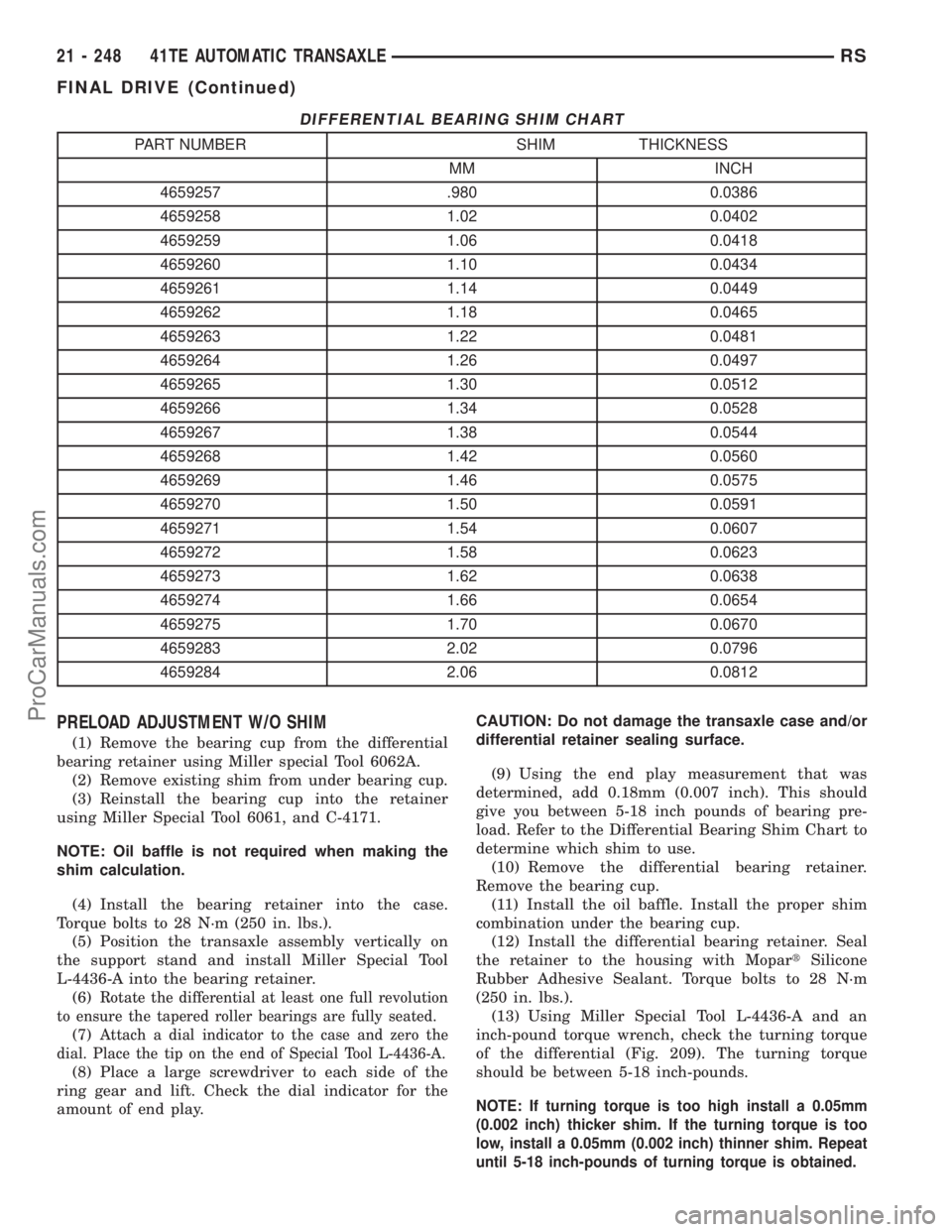
DIFFERENTIAL BEARING SHIM CHART
PART NUMBER SHIM THICKNESS
MM INCH
4659257 .980 0.0386
4659258 1.02 0.0402
4659259 1.06 0.0418
4659260 1.10 0.0434
4659261 1.14 0.0449
4659262 1.18 0.0465
4659263 1.22 0.0481
4659264 1.26 0.0497
4659265 1.30 0.0512
4659266 1.34 0.0528
4659267 1.38 0.0544
4659268 1.42 0.0560
4659269 1.46 0.0575
4659270 1.50 0.0591
4659271 1.54 0.0607
4659272 1.58 0.0623
4659273 1.62 0.0638
4659274 1.66 0.0654
4659275 1.70 0.0670
4659283 2.02 0.0796
4659284 2.06 0.0812
PRELOAD ADJUSTMENT W/O SHIM
(1) Remove the bearing cup from the differential
bearing retainer using Miller special Tool 6062A.
(2) Remove existing shim from under bearing cup.
(3) Reinstall the bearing cup into the retainer
using Miller Special Tool 6061, and C-4171.
NOTE: Oil baffle is not required when making the
shim calculation.
(4) Install the bearing retainer into the case.
Torque bolts to 28 N´m (250 in. lbs.).
(5) Position the transaxle assembly vertically on
the support stand and install Miller Special Tool
L-4436-A into the bearing retainer.
(6)
Rotate the differential at least one full revolution
to ensure the tapered roller bearings are fully seated.
(7)Attach a dial indicator to the case and zero the
dial. Place the tip on the end of Special Tool L-4436-A.
(8) Place a large screwdriver to each side of the
ring gear and lift. Check the dial indicator for the
amount of end play.CAUTION: Do not damage the transaxle case and/or
differential retainer sealing surface.
(9) Using the end play measurement that was
determined, add 0.18mm (0.007 inch). This should
give you between 5-18 inch pounds of bearing pre-
load. Refer to the Differential Bearing Shim Chart to
determine which shim to use.
(10) Remove the differential bearing retainer.
Remove the bearing cup.
(11) Install the oil baffle. Install the proper shim
combination under the bearing cup.
(12) Install the differential bearing retainer. Seal
the retainer to the housing with MopartSilicone
Rubber Adhesive Sealant. Torque bolts to 28 N´m
(250 in. lbs.).
(13) Using Miller Special Tool L-4436-A and an
inch-pound torque wrench, check the turning torque
of the differential (Fig. 209). The turning torque
should be between 5-18 inch-pounds.
NOTE: If turning torque is too high install a 0.05mm
(0.002 inch) thicker shim. If the turning torque is too
low, install a 0.05mm (0.002 inch) thinner shim. Repeat
until 5-18 inch-pounds of turning torque is obtained.
21 - 248 41TE AUTOMATIC TRANSAXLERS
FINAL DRIVE (Continued)
ProCarManuals.com
Page 1915 of 2399
ADJUSTMENT - DIFFERENTIAL SIDE GEAR
END PLAY
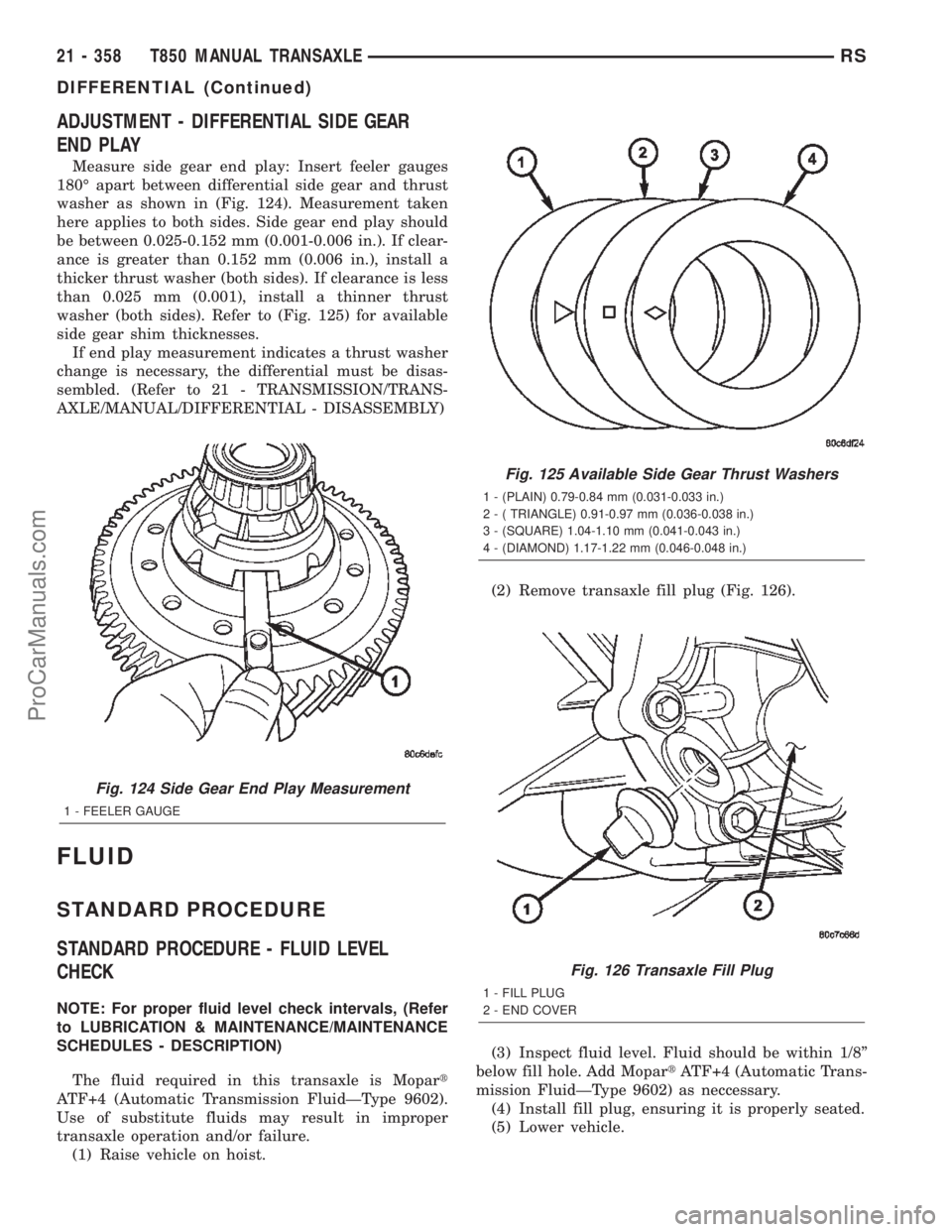
Measure side gear end play: Insert feeler gauges
180É apart between differential side gear and thrust
washer as shown in (Fig. 124). Measurement taken
here applies to both sides. Side gear end play should
be between 0.025-0.152 mm (0.001-0.006 in.). If clear-
ance is greater than 0.152 mm (0.006 in.), install a
thicker thrust washer (both sides). If clearance is less
than 0.025 mm (0.001), install a thinner thrust
washer (both sides). Refer to (Fig. 125) for available
side gear shim thicknesses.
If end play measurement indicates a thrust washer
change is necessary, the differential must be disas-
sembled. (Refer to 21 - TRANSMISSION/TRANS-
AXLE/MANUAL/DIFFERENTIAL - DISASSEMBLY)
FLUID
STANDARD PROCEDURE
STANDARD PROCEDURE - FLUID LEVEL
CHECK
NOTE: For proper fluid level check intervals, (Refer
to LUBRICATION & MAINTENANCE/MAINTENANCE
SCHEDULES - DESCRIPTION)
The fluid required in this transaxle is Mopart
ATF+4 (Automatic Transmission FluidÐType 9602).
Use of substitute fluids may result in improper
transaxle operation and/or failure.
(1) Raise vehicle on hoist.(2) Remove transaxle fill plug (Fig. 126).
(3) Inspect fluid level. Fluid should be within 1/8º
below fill hole. Add MopartATF+4 (Automatic Trans-
mission FluidÐType 9602) as neccessary.
(4) Install fill plug, ensuring it is properly seated.
(5) Lower vehicle.
Fig. 124 Side Gear End Play Measurement
1 - FEELER GAUGE
Fig. 125 Available Side Gear Thrust Washers
1 - (PLAIN) 0.79-0.84 mm (0.031-0.033 in.)
2 - ( TRIANGLE) 0.91-0.97 mm (0.036-0.038 in.)
3 - (SQUARE) 1.04-1.10 mm (0.041-0.043 in.)
4 - (DIAMOND) 1.17-1.22 mm (0.046-0.048 in.)
Fig. 126 Transaxle Fill Plug
1 - FILL PLUG
2 - END COVER
21 - 358 T850 MANUAL TRANSAXLERS
DIFFERENTIAL (Continued)
ProCarManuals.com
Page 2068 of 2399
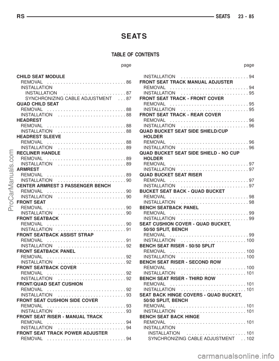
SEATS
TABLE OF CONTENTS
page page
CHILD SEAT MODULE
REMOVAL.............................86
INSTALLATION
INSTALLATION.......................87
SYNCHRONIZING CABLE ADJUSTMENT . . . 87
QUAD CHILD SEAT
REMOVAL.............................88
INSTALLATION.........................88
HEADREST
REMOVAL.............................88
INSTALLATION.........................88
HEADREST SLEEVE
REMOVAL.............................88
INSTALLATION.........................89
RECLINER HANDLE
REMOVAL.............................89
INSTALLATION.........................89
ARMREST
REMOVAL.............................89
INSTALLATION.........................90
CENTER ARMREST 3 PASSENGER BENCH
REMOVAL.............................90
INSTALLATION.........................90
FRONT SEAT
REMOVAL.............................90
INSTALLATION.........................90
FRONT SEATBACK
REMOVAL.............................90
INSTALLATION.........................91
FRONT SEATBACK ASSIST STRAP
REMOVAL.............................91
INSTALLATION.........................92
FRONT SEATBACK PANEL
REMOVAL.............................92
INSTALLATION.........................92
FRONT SEATBACK COVER
REMOVAL.............................92
INSTALLATION.........................92
FRONT/QUAD SEAT CUSHION
REMOVAL.............................92
INSTALLATION.........................93
FRONT SEAT CUSHION SIDE COVER
REMOVAL.............................93
INSTALLATION.........................93
FRONT SEAT RISER - MANUAL TRACK
REMOVAL.............................94
INSTALLATION.........................94
FRONT SEAT TRACK POWER ADJUSTER
REMOVAL.............................94INSTALLATION.........................94
FRONT SEAT TRACK MANUAL ADJUSTER
REMOVAL.............................94
INSTALLATION.........................95
FRONT SEAT TRACK - FRONT COVER
REMOVAL.............................95
INSTALLATION.........................95
FRONT SEAT TRACK - REAR COVER
REMOVAL.............................96
INSTALLATION.........................96
QUAD BUCKET SEAT SIDE SHIELD/CUP
HOLDER
REMOVAL.............................96
INSTALLATION.........................96
QUAD BUCKET SEAT SIDE SHIELD - NO CUP
HOLDER
REMOVAL.............................97
INSTALLATION.........................97
QUAD BUCKET SEAT RISER
REMOVAL.............................97
INSTALLATION.........................97
BUCKET SEAT BACK - QUAD BUCKET
REMOVAL.............................98
INSTALLATION.........................98
BENCH SEATBACK PANEL
REMOVAL.............................99
INSTALLATION.........................99
SEAT CUSHION COVER - QUAD BUCKET,
50/50 SPLIT, BENCH
REMOVAL.............................99
INSTALLATION........................100
BENCH SEAT RISER - 50/50 SPLIT
REMOVAL............................100
INSTALLATION........................100
BENCH SEAT RISER - SECOND ROW
REMOVAL............................100
INSTALLATION........................101
BENCH SEAT RISER - THIRD ROW
REMOVAL............................101
INSTALLATION........................101
SEAT BACK HINGE COVERS - QUAD BUCKET,
50/50 SPLIT, BENCH
REMOVAL............................101
INSTALLATION........................101
BENCH SEAT BACK HINGE
REMOVAL............................101
INSTALLATION
INSTALLATION......................101
SYNCHRONIZING CABLE ADJUSTMENT . . 102
RSSEATS23-85
ProCarManuals.com
Page 2070 of 2399

INSTALLATION
INSTALLATION
(1) Place child restraint seat module in position on
seat back (Fig. 4).
(2) Position seat back hinge interlock lever over
the top of the outboard child restraint seat hinge
(Fig. 5).
(3) Install screws attaching child restraint seat
module hinges to seat back frame lower rail (Fig. 1).
(4) Install screws attaching top of module to seat
back frame upper rail (Fig. 3). Tighten nuts to 7 N´m
(62 in. lbs.) torque.(5) Install push in fasteners attaching upper bol-
ster to child restraint seat module (Fig. 2).
(6) Return seat back to folded position.
(7) Install seat back cover.
(8) Verify child restraint seat operation.
SYNCHRONIZING CABLE ADJUSTMENT
NOTE:
Bench seats equipped with child restraint seats
have an interlock feature that will not allow the seat
back to fold forward with the child seat open.
If the seat back hinges do not release at the same
time the synchronizing cable must be adjusted.
(1) Remove seat from vehicle. Refer to Owner's
Manual for proper procedures.
(2) Disengage cable from the recline mechanism by
pulling the cable end toward the front of the seat
(Fig. 6).
(3) Pull U-shaped locking tab on self-adjusting
mehcanism to disengage auto-adjust feature.
(4) Reattach self-adjusting mechanism, pulling
against spring load to tighten cable.
(5) Press locking tab onto the adjusting mecha-
nism to lock into place.
Fig. 4 CHILD RESTRAINT SEAT MODULE
1 - 1ST REAR SEAT BACK
2 - CHILD RESTRAINT SEAT MODULE
3 - SEAT BACK HINGE INTERLOCK LEVER
Fig. 5 INTERLOCK LEVER
1 - CHILD RESTRAINT SEAT HINGE
2 - SEAT BACK HINGE INTERLOCK LEVER
3 - 1ST REAR SEAT BACK
4 - SEAT BACK FRAME RAIL
RSSEATS23-87
CHILD SEAT MODULE (Continued)
ProCarManuals.com
Page 2074 of 2399
(1) Remove head rest sleeves. (Refer to 23 - BODY/
SEATS/HEADREST SLEEVE - REMOVAL)
(2) Remove the armrest. (Refer to 23 - BODY/
SEATS/ARMREST - REMOVAL)
(3) Remove the seatback recliner lever.
(4) Remove the lumbar adjustment lever.
(5) Remove both seat cushion side covers. (Refer to
23 - BODY/SEATS/FRONT SEAT CUSHION SIDE
COVER - REMOVAL)
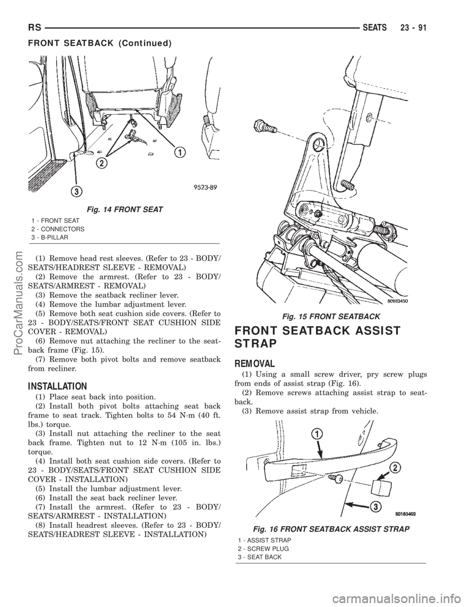
(6) Remove nut attaching the recliner to the seat-
back frame (Fig. 15).
(7) Remove both pivot bolts and remove seatback
from recliner.
INSTALLATION
(1) Place seat back into position.
(2) Install both pivot bolts attaching seat back
frame to seat track. Tighten bolts to 54 N´m (40 ft.
lbs.) torque.
(3) Install nut attaching the recliner to the seat
back frame. Tighten nut to 12 N´m (105 in. lbs.)
torque.
(4) Install both seat cushion side covers. (Refer to
23 - BODY/SEATS/FRONT SEAT CUSHION SIDE
COVER - INSTALLATION)
(5) Install the lumbar adjustment lever.
(6) Install the seat back recliner lever.
(7) Install the armrest. (Refer to 23 - BODY/
SEATS/ARMREST - INSTALLATION)
(8) Install headrest sleeves. (Refer to 23 - BODY/
SEATS/HEADREST SLEEVE - INSTALLATION)
FRONT SEATBACK ASSIST
STRAP
REMOVAL
(1) Using a small screw driver, pry screw plugs
from ends of assist strap (Fig. 16).
(2) Remove screws attaching assist strap to seat-
back.
(3) Remove assist strap from vehicle.
Fig. 14 FRONT SEAT
1 - FRONT SEAT
2 - CONNECTORS
3 - B-PILLAR
Fig. 15 FRONT SEATBACK
Fig. 16 FRONT SEATBACK ASSIST STRAP
1 - ASSIST STRAP
2 - SCREW PLUG
3 - SEAT BACK
RSSEATS23-91
FRONT SEATBACK (Continued)
ProCarManuals.com
Page 2085 of 2399
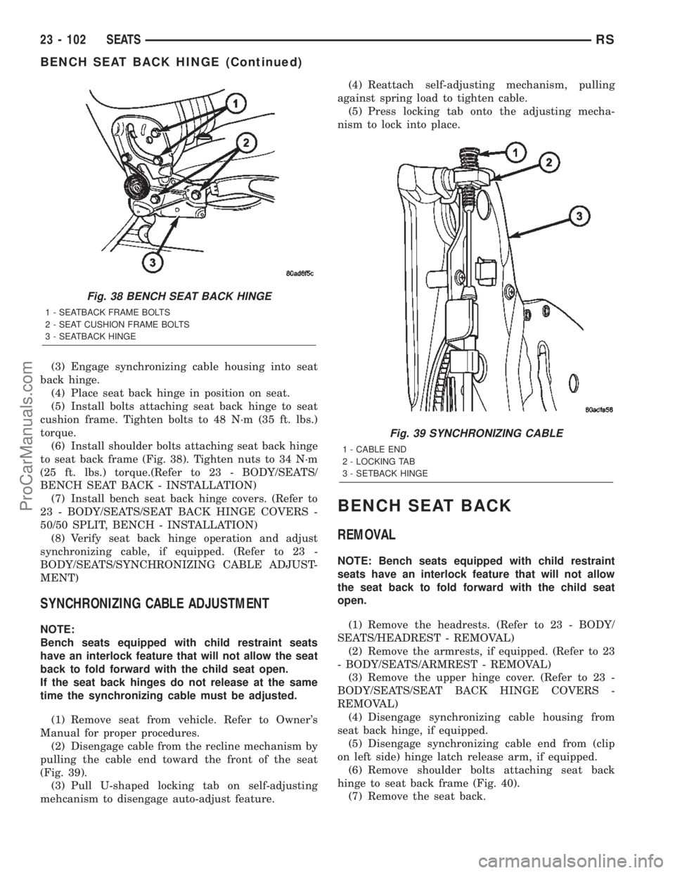
(3) Engage synchronizing cable housing into seat
back hinge.
(4) Place seat back hinge in position on seat.
(5) Install bolts attaching seat back hinge to seat
cushion frame. Tighten bolts to 48 N´m (35 ft. lbs.)
torque.
(6) Install shoulder bolts attaching seat back hinge
to seat back frame (Fig. 38). Tighten nuts to 34 N´m
(25 ft. lbs.) torque.(Refer to 23 - BODY/SEATS/
BENCH SEAT BACK - INSTALLATION)
(7) Install bench seat back hinge covers. (Refer to
23 - BODY/SEATS/SEAT BACK HINGE COVERS -
50/50 SPLIT, BENCH - INSTALLATION)
(8) Verify seat back hinge operation and adjust
synchronizing cable, if equipped. (Refer to 23 -
BODY/SEATS/SYNCHRONIZING CABLE ADJUST-
MENT)
SYNCHRONIZING CABLE ADJUSTMENT
NOTE:
Bench seats equipped with child restraint seats
have an interlock feature that will not allow the seat
back to fold forward with the child seat open.
If the seat back hinges do not release at the same
time the synchronizing cable must be adjusted.
(1) Remove seat from vehicle. Refer to Owner's
Manual for proper procedures.
(2) Disengage cable from the recline mechanism by
pulling the cable end toward the front of the seat
(Fig. 39).
(3) Pull U-shaped locking tab on self-adjusting
mehcanism to disengage auto-adjust feature.(4) Reattach self-adjusting mechanism, pulling
against spring load to tighten cable.
(5) Press locking tab onto the adjusting mecha-
nism to lock into place.
BENCH SEAT BACK
REMOVAL
NOTE: Bench seats equipped with child restraint
seats have an interlock feature that will not allow
the seat back to fold forward with the child seat
open.
(1) Remove the headrests. (Refer to 23 - BODY/
SEATS/HEADREST - REMOVAL)
(2) Remove the armrests, if equipped. (Refer to 23
- BODY/SEATS/ARMREST - REMOVAL)
(3) Remove the upper hinge cover. (Refer to 23 -
BODY/SEATS/SEAT BACK HINGE COVERS -
REMOVAL)
(4) Disengage synchronizing cable housing from
seat back hinge, if equipped.
(5) Disengage synchronizing cable end from (clip
on left side) hinge latch release arm, if equipped.
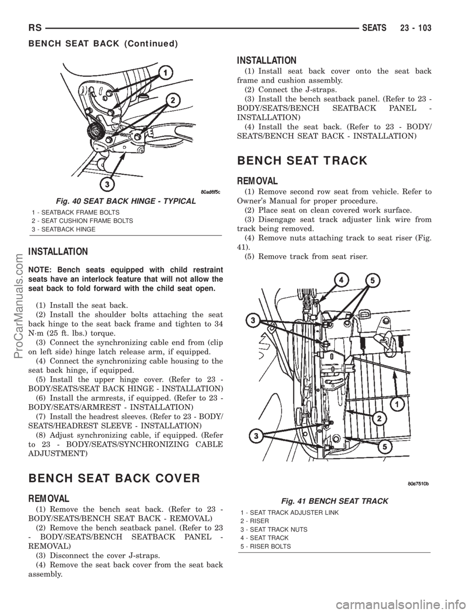
(6) Remove shoulder bolts attaching seat back
hinge to seat back frame (Fig. 40).
(7) Remove the seat back.
Fig. 38 BENCH SEAT BACK HINGE
1 - SEATBACK FRAME BOLTS
2 - SEAT CUSHION FRAME BOLTS
3 - SEATBACK HINGE
Fig. 39 SYNCHRONIZING CABLE
1 - CABLE END
2 - LOCKING TAB
3 - SETBACK HINGE
23 - 102 SEATSRS
BENCH SEAT BACK HINGE (Continued)
ProCarManuals.com
Page 2086 of 2399
INSTALLATION
NOTE: Bench seats equipped with child restraint
seats have an interlock feature that will not allow the
seat back to fold forward with the child seat open.
(1) Install the seat back.
(2) Install the shoulder bolts attaching the seat
back hinge to the seat back frame and tighten to 34
N´m (25 ft. lbs.) torque.
(3) Connect the synchronizing cable end from (clip
on left side) hinge latch release arm, if equipped.
(4) Connect the synchronizing cable housing to the
seat back hinge, if equipped.
(5)
Install the upper hinge cover. (Refer to 23 -
BODY/SEATS/SEAT BACK HINGE - INSTALLATION)
(6) Install the armrests, if equipped. (Refer to 23 -
BODY/SEATS/ARMREST - INSTALLATION)
(7)
Install the headrest sleeves. (Refer to 23 - BODY/
SEATS/HEADREST SLEEVE - INSTALLATION)
(8) Adjust synchronizing cable, if equipped. (Refer
to 23 - BODY/SEATS/SYNCHRONIZING CABLE
ADJUSTMENT)
BENCH SEAT BACK COVER
REMOVAL
(1) Remove the bench seat back. (Refer to 23 -
BODY/SEATS/BENCH SEAT BACK - REMOVAL)
(2) Remove the bench seatback panel. (Refer to 23
- BODY/SEATS/BENCH SEATBACK PANEL -
REMOVAL)
(3) Disconnect the cover J-straps.
(4) Remove the seat back cover from the seat back
assembly.
INSTALLATION
(1) Install seat back cover onto the seat back
frame and cushion assembly.
(2) Connect the J-straps.
(3) Install the bench seatback panel. (Refer to 23 -
BODY/SEATS/BENCH SEATBACK PANEL -
INSTALLATION)
(4) Install the seat back. (Refer to 23 - BODY/
SEATS/BENCH SEAT BACK - INSTALLATION)
BENCH SEAT TRACK
REMOVAL
(1) Remove second row seat from vehicle. Refer to
Owner's Manual for proper procedure.
(2) Place seat on clean covered work surface.
(3) Disengage seat track adjuster link wire from
track being removed.
(4) Remove nuts attaching track to seat riser (Fig.
41).
(5) Remove track from seat riser.
Fig. 40 SEAT BACK HINGE - TYPICAL
1 - SEATBACK FRAME BOLTS
2 - SEAT CUSHION FRAME BOLTS
3 - SEATBACK HINGE
Fig. 41 BENCH SEAT TRACK
1 - SEAT TRACK ADJUSTER LINK
2 - RISER
3 - SEAT TRACK NUTS
4 - SEAT TRACK
5 - RISER BOLTS
RSSEATS23 - 103
BENCH SEAT BACK (Continued)
ProCarManuals.com
Page 2245 of 2399
FRONT CONTROL PANEL
The front control panel and integral computer is
mounted in the instrument panel.
The instrument panel mounted control and inte-
gral computer contains:
²a power button which allows the system to be
completely turned off.
²rear window defogger on/off switch.
²slide controls for completely independent side-to-
side temperature control of the discharge air. The full
range of temperature that the system can produce in
any mode is available on either side of the vehicle by
independently positioning the slide controls on the
instrument panel.
²air recirculation button. The Recirculate button
contains an LED that illuminates to show when the
function is in operation.
²an air conditioning button that allows the com-
pressor to be turned on/off. The Snowflake button
contains an LED that illuminates to shown when the
function is in operation.
²rotary knobs for front and rear fan speed selec-
tion.
²a rotary knob for mode control.
REAR CONTROL PANEL
A rear control panel centrally mounted on the
headliner has a rotary adjustment for temperature
and fan speed control of the rear unit by intermedi-
ate seat passengers when the front control rear knob
is set to the rear position.
DESCRIPTION - THREE ZONE AUTOMATIC
TEMPERATURE CONTROL
The Three-Zone Automatic Temperature Control
(ATC) allows occupants to select a comfort tempera-
ture, which is the perceived temperature level not
the actual passenger compartment air temperature.
The Three Zone Automatic Temperature Control
system includes a dust and odor air filter. The filter
element is the same size as the air conditioning evap-
orator to ensure ample capacity. A door at the base of
the heater and air conditioning housing below the
glove box provides easy access to the filter element.
The ATC computer utilizes integrated circuitry and
information carried on the Programmable Communi-
cations Interface (PCI) data bus network to monitor
many sensors and switch inputs throughout the vehi-
cle. In response to those inputs, the internal circuitry
and programming of the ATC computer allow it to
control electronic functions and features of the ATC
system. The inputs to the ATC computer are:
²Vehicle Speed/Engine RPM± The ATC com-
puter monitors engine RPM, vehicle speed and Man-
ifold Absolute Pressure information from the PCM.²Coolant Temperature± ATC computer moni-
tors Coolant temperature received from the PCM and
converts it to degrees Fahrenheit.
²Ambient Temperature± ATC computer moni-
tors Ambient temperature from the Compass Mini
Trip Computer (CMTC) and converts it to degrees
Fahrenheit.
²Engine Miscellaneous Sensor Status±ATC
computer monitors A/C disable information from the
PCM.
²Refrigerant Pressure± ATC computer moni-
tors Barometric Pressure, Intake Air Temperature,
High Side Pressure and Methanol Content as broad-
cast by the PCM.
²Door Ajar Status± The ATC computer moni-
tors Driver Front Door, Passenger Front Door, Left
Rear Door, Right Rear Door and Liftgate ajar infor-
mation, as identified by the Body Control Module
(BCM), to determine if all in-car temperatures should
be maintained.
²Dimming± The ATC computer monitors dim-
ming status from the BCM to determine the required
level of brightness and will dim accordingly.
²Vehicle Odometer± The ATC computer moni-
tors the vehicle odometer information from the BCM
to prevent flashing the VF tube icons if the manual
motor calibration or manual cool down tests have
failed. Flashing of the display icons will cease when
the vehicle odometer is greater than 3 miles.
²English Metric± The ATC computer monitors
the English/Metric information broadcast by the
CMTC. The set temp displays for both the front and
rear control heads will be set accordingly.
²Vehicle Identification Number± The ATC
computer monitors the last eight characters of the
VIN broadcast by the PCM and compares it to the
information stored in EEPROM. If it is different, the
new number will be stored over the old one and a
motor calibration shall be initiated.
²A/C System Information± The ATC computer
will send a message for Evaporator Temperature too
Low, Fan Blower Relay status, Evaporator Sensor
Failure, Rear Window Defogger Relay and A/C Select.
FRONT CONTROL PANEL
The front control panel and integral computer is
mounted in the instrument panel.
The instrument panel mounted control and inte-
gral computer contains:
²A power button which allows the system to be
completely turned off. The display is blank when the
system is off.
²Three rocker switches that select comfort tem-
peratures from 15É to 30É C (59É to 85É F), which are
shown in the vacuum-fluorescent digital control dis-
play. If the set temp is 59 and the down button is
24 - 2 HEATING & AIR CONDITIONINGRS
HEATING & AIR CONDITIONING (Continued)
ProCarManuals.com