2002 CHRYSLER CARAVAN power steering fluid
[x] Cancel search: power steering fluidPage 1508 of 2399
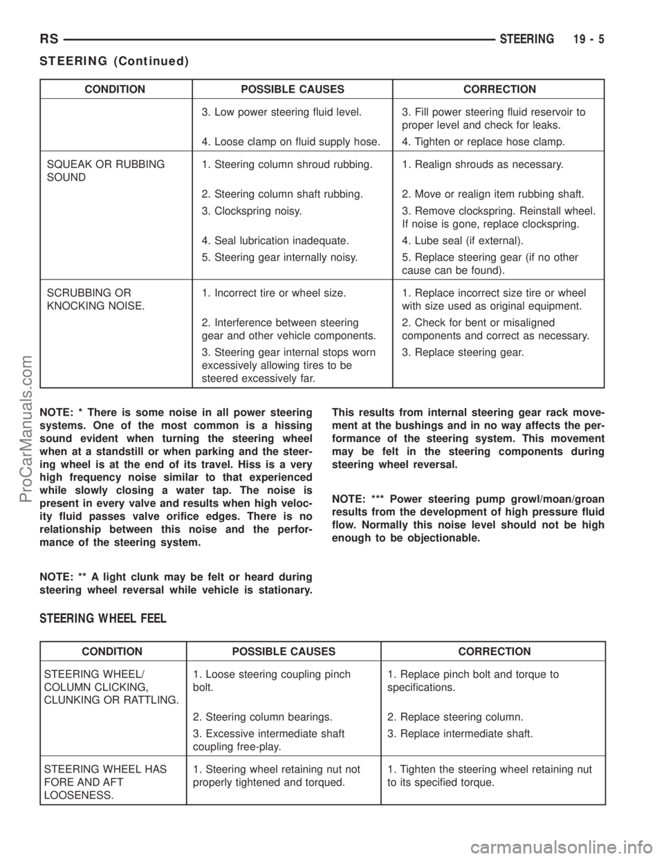
CONDITION POSSIBLE CAUSES CORRECTION
3. Low power steering fluid level. 3. Fill power steering fluid reservoir to
proper level and check for leaks.
4. Loose clamp on fluid supply hose. 4. Tighten or replace hose clamp.
SQUEAK OR RUBBING
SOUND1. Steering column shroud rubbing. 1. Realign shrouds as necessary.
2. Steering column shaft rubbing. 2. Move or realign item rubbing shaft.
3. Clockspring noisy. 3. Remove clockspring. Reinstall wheel.
If noise is gone, replace clockspring.
4. Seal lubrication inadequate. 4. Lube seal (if external).
5. Steering gear internally noisy. 5. Replace steering gear (if no other
cause can be found).
SCRUBBING OR
KNOCKING NOISE.1. Incorrect tire or wheel size. 1. Replace incorrect size tire or wheel
with size used as original equipment.
2. Interference between steering
gear and other vehicle components.2. Check for bent or misaligned
components and correct as necessary.
3. Steering gear internal stops worn
excessively allowing tires to be
steered excessively far.3. Replace steering gear.
NOTE: * There is some noise in all power steering
systems. One of the most common is a hissing
sound evident when turning the steering wheel
when at a standstill or when parking and the steer-
ing wheel is at the end of its travel. Hiss is a very
high frequency noise similar to that experienced
while slowly closing a water tap. The noise is
present in every valve and results when high veloc-
ity fluid passes valve orifice edges. There is no
relationship between this noise and the perfor-
mance of the steering system.
NOTE: ** A light clunk may be felt or heard during
steering wheel reversal while vehicle is stationary.This results from internal steering gear rack move-
ment at the bushings and in no way affects the per-
formance of the steering system. This movement
may be felt in the steering components during
steering wheel reversal.
NOTE: *** Power steering pump growl/moan/groan
results from the development of high pressure fluid
flow. Normally this noise level should not be high
enough to be objectionable.
STEERING WHEEL FEEL
CONDITION POSSIBLE CAUSES CORRECTION
STEERING WHEEL/
COLUMN CLICKING,
CLUNKING OR RATTLING.1. Loose steering coupling pinch
bolt.1. Replace pinch bolt and torque to
specifications.
2. Steering column bearings. 2. Replace steering column.
3. Excessive intermediate shaft
coupling free-play.3. Replace intermediate shaft.
STEERING WHEEL HAS
FORE AND AFT
LOOSENESS.1. Steering wheel retaining nut not
properly tightened and torqued.1. Tighten the steering wheel retaining nut
to its specified torque.
RSSTEERING19-5
STEERING (Continued)
ProCarManuals.com
Page 1509 of 2399
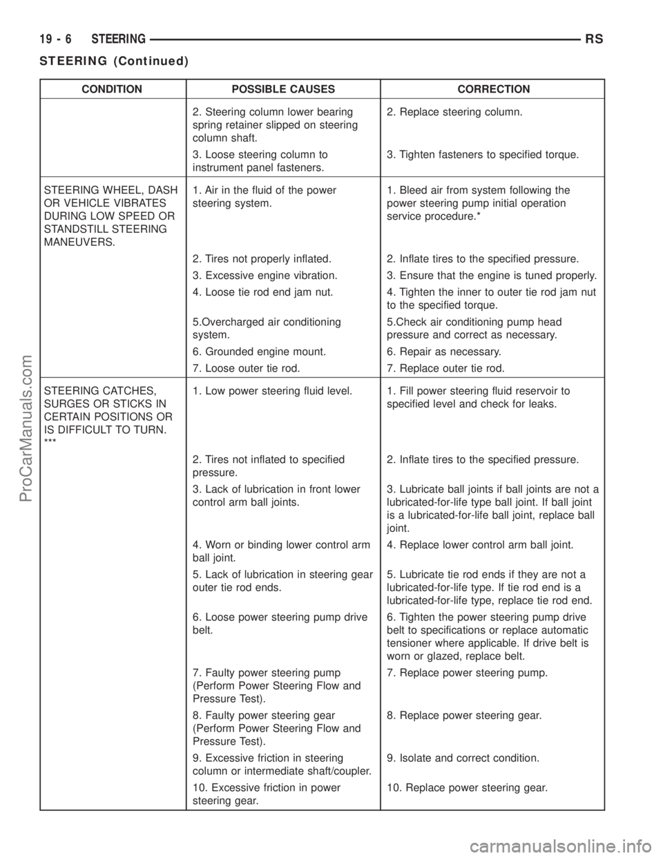
CONDITION POSSIBLE CAUSES CORRECTION
2. Steering column lower bearing
spring retainer slipped on steering
column shaft.2. Replace steering column.
3. Loose steering column to
instrument panel fasteners.3. Tighten fasteners to specified torque.
STEERING WHEEL, DASH
OR VEHICLE VIBRATES
DURING LOW SPEED OR
STANDSTILL STEERING
MANEUVERS.1. Air in the fluid of the power
steering system.1. Bleed air from system following the
power steering pump initial operation
service procedure.*
2. Tires not properly inflated. 2. Inflate tires to the specified pressure.
3. Excessive engine vibration. 3. Ensure that the engine is tuned properly.
4. Loose tie rod end jam nut. 4. Tighten the inner to outer tie rod jam nut
to the specified torque.
5.Overcharged air conditioning
system.5.Check air conditioning pump head
pressure and correct as necessary.
6. Grounded engine mount. 6. Repair as necessary.
7. Loose outer tie rod. 7. Replace outer tie rod.
STEERING CATCHES,
SURGES OR STICKS IN
CERTAIN POSITIONS OR
IS DIFFICULT TO TURN.
***1. Low power steering fluid level. 1. Fill power steering fluid reservoir to
specified level and check for leaks.
2. Tires not inflated to specified
pressure.2. Inflate tires to the specified pressure.
3. Lack of lubrication in front lower
control arm ball joints.3. Lubricate ball joints if ball joints are not a
lubricated-for-life type ball joint. If ball joint
is a lubricated-for-life ball joint, replace ball
joint.
4. Worn or binding lower control arm
ball joint.4. Replace lower control arm ball joint.
5. Lack of lubrication in steering gear
outer tie rod ends.5. Lubricate tie rod ends if they are not a
lubricated-for-life type. If tie rod end is a
lubricated-for-life type, replace tie rod end.
6. Loose power steering pump drive
belt.6. Tighten the power steering pump drive
belt to specifications or replace automatic
tensioner where applicable. If drive belt is
worn or glazed, replace belt.
7. Faulty power steering pump
(Perform Power Steering Flow and
Pressure Test).7. Replace power steering pump.
8. Faulty power steering gear
(Perform Power Steering Flow and
Pressure Test).8. Replace power steering gear.
9. Excessive friction in steering
column or intermediate shaft/coupler.9. Isolate and correct condition.
10. Excessive friction in power
steering gear.10. Replace power steering gear.
19 - 6 STEERINGRS
STEERING (Continued)
ProCarManuals.com
Page 1510 of 2399
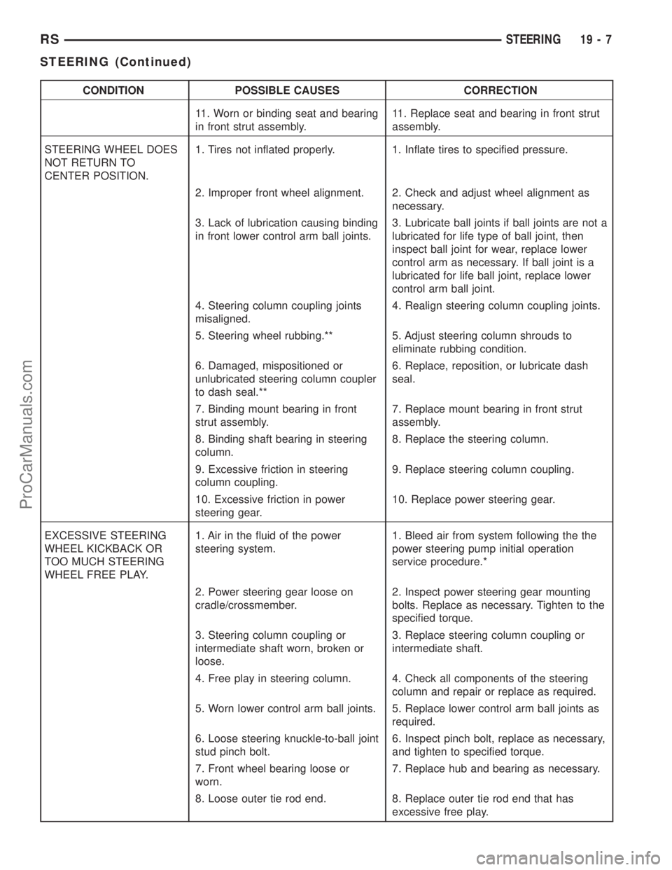
CONDITION POSSIBLE CAUSES CORRECTION
11. Worn or binding seat and bearing
in front strut assembly.11. Replace seat and bearing in front strut
assembly.
STEERING WHEEL DOES
NOT RETURN TO
CENTER POSITION.1. Tires not inflated properly. 1. Inflate tires to specified pressure.
2. Improper front wheel alignment. 2. Check and adjust wheel alignment as
necessary.
3. Lack of lubrication causing binding
in front lower control arm ball joints.3. Lubricate ball joints if ball joints are not a
lubricated for life type of ball joint, then
inspect ball joint for wear, replace lower
control arm as necessary. If ball joint is a
lubricated for life ball joint, replace lower
control arm ball joint.
4. Steering column coupling joints
misaligned.4. Realign steering column coupling joints.
5. Steering wheel rubbing.** 5. Adjust steering column shrouds to
eliminate rubbing condition.
6. Damaged, mispositioned or
unlubricated steering column coupler
to dash seal.**6. Replace, reposition, or lubricate dash
seal.
7. Binding mount bearing in front
strut assembly.7. Replace mount bearing in front strut
assembly.
8. Binding shaft bearing in steering
column.8. Replace the steering column.
9. Excessive friction in steering
column coupling.9. Replace steering column coupling.
10. Excessive friction in power
steering gear.10. Replace power steering gear.
EXCESSIVE STEERING
WHEEL KICKBACK OR
TOO MUCH STEERING
WHEEL FREE PLAY.1. Air in the fluid of the power
steering system.1. Bleed air from system following the the
power steering pump initial operation
service procedure.*
2. Power steering gear loose on
cradle/crossmember.2. Inspect power steering gear mounting
bolts. Replace as necessary. Tighten to the
specified torque.
3. Steering column coupling or
intermediate shaft worn, broken or
loose.3. Replace steering column coupling or
intermediate shaft.
4. Free play in steering column. 4. Check all components of the steering
column and repair or replace as required.
5. Worn lower control arm ball joints. 5. Replace lower control arm ball joints as
required.
6. Loose steering knuckle-to-ball joint
stud pinch bolt.6. Inspect pinch bolt, replace as necessary,
and tighten to specified torque.
7. Front wheel bearing loose or
worn.7. Replace hub and bearing as necessary.
8. Loose outer tie rod end. 8. Replace outer tie rod end that has
excessive free play.
RSSTEERING19-7
STEERING (Continued)
ProCarManuals.com
Page 1511 of 2399
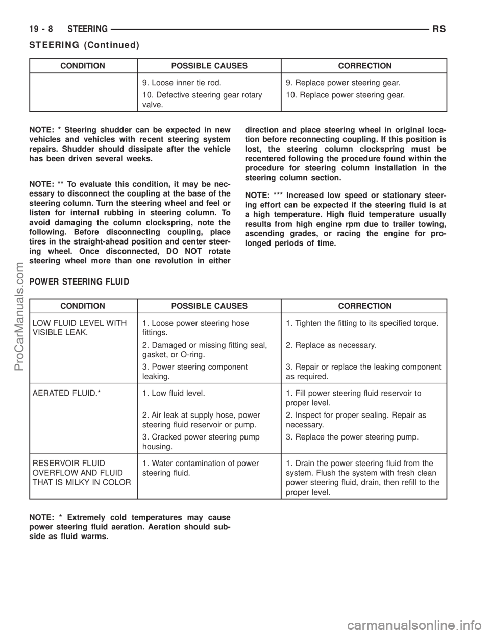
CONDITION POSSIBLE CAUSES CORRECTION
9. Loose inner tie rod. 9. Replace power steering gear.
10. Defective steering gear rotary
valve.10. Replace power steering gear.
NOTE: * Steering shudder can be expected in new
vehicles and vehicles with recent steering system
repairs. Shudder should dissipate after the vehicle
has been driven several weeks.
NOTE: ** To evaluate this condition, it may be nec-
essary to disconnect the coupling at the base of the
steering column. Turn the steering wheel and feel or
listen for internal rubbing in steering column. To
avoid damaging the column clockspring, note the
following. Before disconnecting coupling, place
tires in the straight-ahead position and center steer-
ing wheel. Once disconnected, DO NOT rotate
steering wheel more than one revolution in eitherdirection and place steering wheel in original loca-
tion before reconnecting coupling. If this position is
lost, the steering column clockspring must be
recentered following the procedure found within the
procedure for steering column installation in the
steering column section.
NOTE: *** Increased low speed or stationary steer-
ing effort can be expected if the steering fluid is at
a high temperature. High fluid temperature usually
results from high engine rpm due to trailer towing,
ascending grades, or racing the engine for pro-
longed periods of time.
POWER STEERING FLUID
CONDITION POSSIBLE CAUSES CORRECTION
LOW FLUID LEVEL WITH
VISIBLE LEAK.1. Loose power steering hose
fittings.1. Tighten the fitting to its specified torque.
2. Damaged or missing fitting seal,
gasket, or O-ring.2. Replace as necessary.
3. Power steering component
leaking.3. Repair or replace the leaking component
as required.
AERATED FLUID.* 1. Low fluid level. 1. Fill power steering fluid reservoir to
proper level.
2. Air leak at supply hose, power
steering fluid reservoir or pump.2. Inspect for proper sealing. Repair as
necessary.
3. Cracked power steering pump
housing.3. Replace the power steering pump.
RESERVOIR FLUID
OVERFLOW AND FLUID
THAT IS MILKY IN COLOR1. Water contamination of power
steering fluid.1. Drain the power steering fluid from the
system. Flush the system with fresh clean
power steering fluid, drain, then refill to the
proper level.
NOTE: * Extremely cold temperatures may cause
power steering fluid aeration. Aeration should sub-
side as fluid warms.
19 - 8 STEERINGRS
STEERING (Continued)
ProCarManuals.com
Page 1512 of 2399
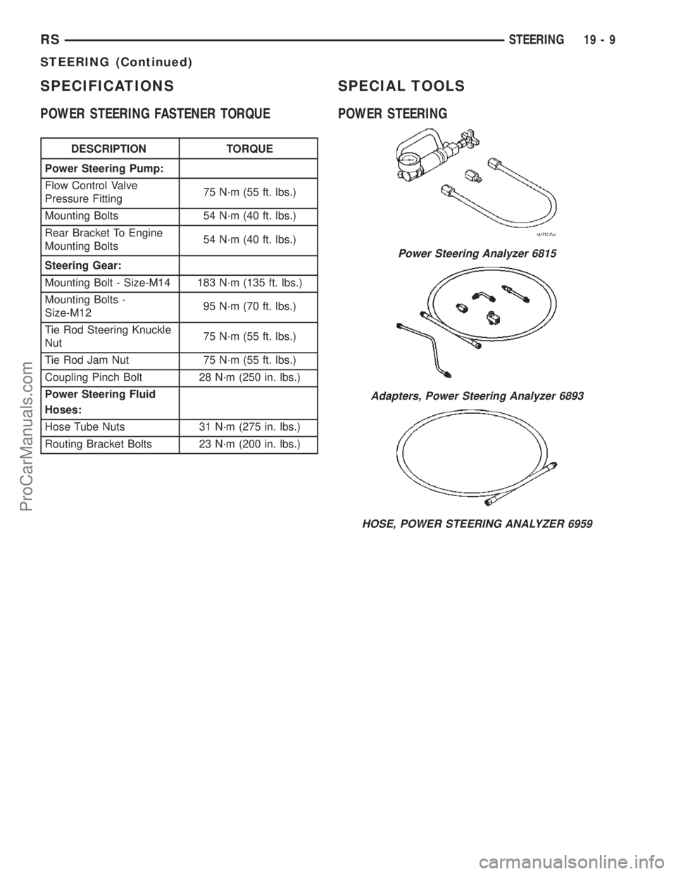
SPECIFICATIONS
POWER STEERING FASTENER TORQUE
DESCRIPTION TORQUE
Power Steering Pump:
Flow Control Valve
Pressure Fitting75 N´m (55 ft. lbs.)
Mounting Bolts 54 N´m (40 ft. lbs.)
Rear Bracket To Engine
Mounting Bolts54 N´m (40 ft. lbs.)
Steering Gear:
Mounting Bolt - Size-M14 183 N´m (135 ft. lbs.)
Mounting Bolts -
Size-M1295 N´m (70 ft. lbs.)
Tie Rod Steering Knuckle
Nut75 N´m (55 ft. lbs.)
Tie Rod Jam Nut 75 N´m (55 ft. lbs.)
Coupling Pinch Bolt 28 N´m (250 in. lbs.)
Power Steering Fluid
Hoses:
Hose Tube Nuts 31 N´m (275 in. lbs.)
Routing Bracket Bolts 23 N´m (200 in. lbs.)
SPECIAL TOOLS
POWER STEERING
Power Steering Analyzer 6815
Adapters, Power Steering Analyzer 6893
HOSE, POWER STEERING ANALYZER 6959
RSSTEERING19-9
STEERING (Continued)
ProCarManuals.com
Page 1529 of 2399
GEAR
TABLE OF CONTENTS
page page
GEAR
DESCRIPTION.........................26
OPERATION...........................26
WARNING
WARNINGS AND CAUTIONS.............26
REMOVAL
REMOVAL - LHD GEAR.................26
REMOVAL - RHD GEAR................29INSTALLATION
INSTALLATION - LHD GEAR.............32
INSTALLATION - RHD GEAR.............33
SPECIAL TOOLS
POWER STEERING GEAR..............34
OUTER TIE ROD
REMOVAL.............................34
INSTALLATION.........................34
GEAR
DESCRIPTION
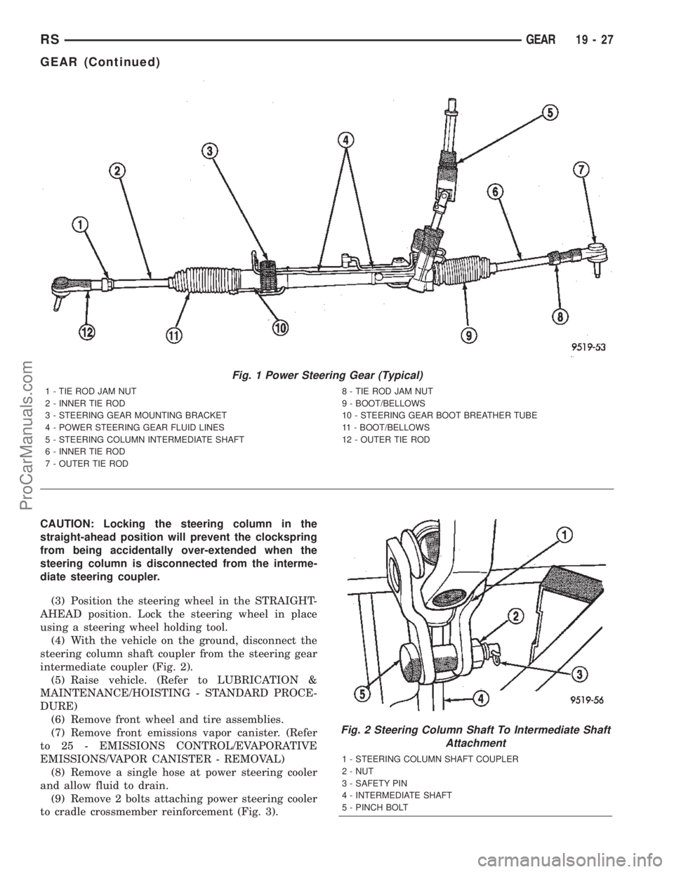
This vehicle is equipped with a rack and pinion
power steering gear (Fig. 1). It is mounted to the
underside of the front suspension cradle/crossmem-
ber.
The steering column is attached to the gear
through the use of an intermediate shaft and cou-
plers. The outer ends of the power steering gear's
outer tie rods connect to the steering knuckles.
NOTE: The power steering gear should NOT be ser-
viced or adjusted unless DaimlerChrysler Corpora-
tion authorizes. If a malfunction or oil leak occurs,
the complete steering gear should be replaced.
Only the outer tie rods may be replaced separately
from the rest of the gear.
OPERATION
Turning of the steering wheel is converted into lin-
ear (side-to-side) travel through the meshing of the
helical pinion teeth with the rack teeth in the steer-
ing gear. This travel pushes and pulls the tie rods to
change the direction of the vehicle's front wheels.
Power assist steering provided by the power steer-
ing pump is controlled by an open center, rotary type
control valve which directs oil from the pump to
either side of the integral rack piston upon demand.
Road feel is controlled by the diameter of a torsion
bar which initially steers the vehicle. As required
steering effort increases, as in a turn, the torsion bar
twists, causing relative rotary motion between the
rotary valve body and the valve spool. This move-
ment directs oil behind the integral rack piston
which, in turn, builds hydraulic pressure and assists
in the turning effort.Manual steering control of the vehicle can be main-
tained if power steering assist is lost. However,
under this condition, steering effort is significantly
increased.
WARNING
WARNINGS AND CAUTIONS
WARNING: POWER STEERING FLUID, ENGINE
PARTS AND EXHAUST SYSTEM MAY BE
EXTREMELY HOT IF ENGINE HAS BEEN RUNNING.
DO NOT START ENGINE WITH ANY LOOSE OR DIS-
CONNECTED HOSES. DO NOT ALLOW HOSES TO
TOUCH HOT EXHAUST MANIFOLD OR CATALYST.
WARNING: FLUID LEVEL SHOULD BE CHECKED
WITH THE ENGINE OFF TO PREVENT PERSONAL
INJURY FROM MOVING PARTS.
CAUTION: When the system is open, cap all open
ends of the hoses, power steering pump fittings or
power steering gear ports to prevent entry of for-
eign material into the components.
REMOVAL
REMOVAL - LHD GEAR
(1) Remove cap from power steering fluid reser-
voir.
(2) Using a siphon pump, remove as much fluid as
possible from the power steering fluid reservoir.Use
care not to damage the filter mesh below the
fluid surface.
19 - 26 GEARRS
ProCarManuals.com
Page 1530 of 2399
CAUTION: Locking the steering column in the
straight-ahead position will prevent the clockspring
from being accidentally over-extended when the
steering column is disconnected from the interme-
diate steering coupler.
(3) Position the steering wheel in the STRAIGHT-
AHEAD position. Lock the steering wheel in place
using a steering wheel holding tool.
(4) With the vehicle on the ground, disconnect the
steering column shaft coupler from the steering gear
intermediate coupler (Fig. 2).
(5) Raise vehicle. (Refer to LUBRICATION &
MAINTENANCE/HOISTING - STANDARD PROCE-
DURE)
(6) Remove front wheel and tire assemblies.
(7) Remove front emissions vapor canister. (Refer
to 25 - EMISSIONS CONTROL/EVAPORATIVE
EMISSIONS/VAPOR CANISTER - REMOVAL)
(8) Remove a single hose at power steering cooler
and allow fluid to drain.
(9) Remove 2 bolts attaching power steering cooler
to cradle crossmember reinforcement (Fig. 3).
Fig. 1 Power Steering Gear (Typical)
1 - TIE ROD JAM NUT
2 - INNER TIE ROD
3 - STEERING GEAR MOUNTING BRACKET
4 - POWER STEERING GEAR FLUID LINES
5 - STEERING COLUMN INTERMEDIATE SHAFT
6 - INNER TIE ROD
7 - OUTER TIE ROD8 - TIE ROD JAM NUT
9 - BOOT/BELLOWS
10 - STEERING GEAR BOOT BREATHER TUBE
11 - BOOT/BELLOWS
12 - OUTER TIE ROD
Fig. 2 Steering Column Shaft To Intermediate Shaft
Attachment
1 - STEERING COLUMN SHAFT COUPLER
2 - NUT
3 - SAFETY PIN
4 - INTERMEDIATE SHAFT
5 - PINCH BOLT
RSGEAR19-27
GEAR (Continued)
ProCarManuals.com
Page 1532 of 2399
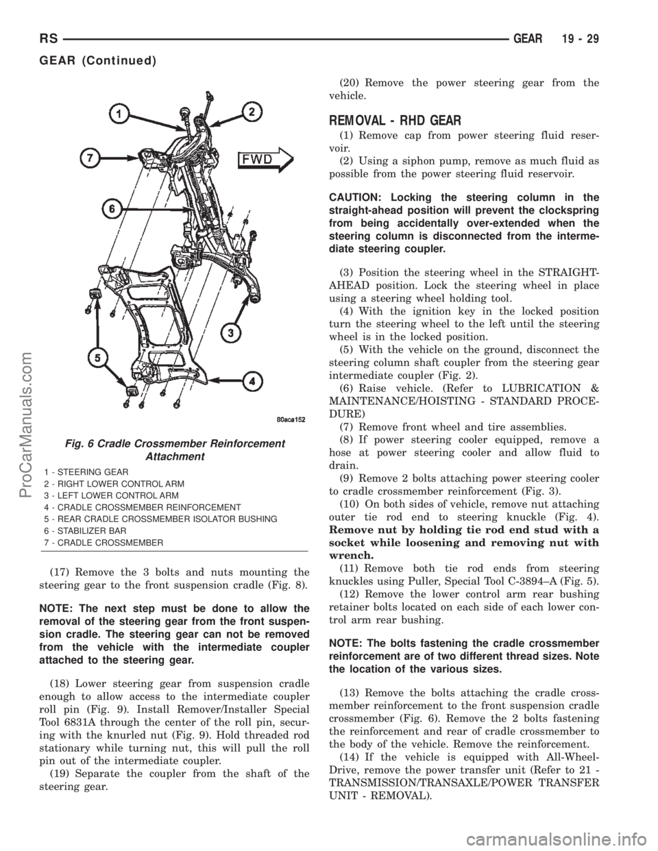
(17) Remove the 3 bolts and nuts mounting the
steering gear to the front suspension cradle (Fig. 8).
NOTE: The next step must be done to allow the
removal of the steering gear from the front suspen-
sion cradle. The steering gear can not be removed
from the vehicle with the intermediate coupler
attached to the steering gear.
(18) Lower steering gear from suspension cradle
enough to allow access to the intermediate coupler
roll pin (Fig. 9). Install Remover/Installer Special
Tool 6831A through the center of the roll pin, secur-
ing with the knurled nut (Fig. 9). Hold threaded rod
stationary while turning nut, this will pull the roll
pin out of the intermediate coupler.
(19) Separate the coupler from the shaft of the
steering gear.(20) Remove the power steering gear from the
vehicle.
REMOVAL - RHD GEAR
(1) Remove cap from power steering fluid reser-
voir.
(2) Using a siphon pump, remove as much fluid as
possible from the power steering fluid reservoir.
CAUTION: Locking the steering column in the
straight-ahead position will prevent the clockspring
from being accidentally over-extended when the
steering column is disconnected from the interme-
diate steering coupler.
(3) Position the steering wheel in the STRAIGHT-
AHEAD position. Lock the steering wheel in place
using a steering wheel holding tool.
(4) With the ignition key in the locked position
turn the steering wheel to the left until the steering
wheel is in the locked position.
(5) With the vehicle on the ground, disconnect the
steering column shaft coupler from the steering gear
intermediate coupler (Fig. 2).
(6) Raise vehicle. (Refer to LUBRICATION &
MAINTENANCE/HOISTING - STANDARD PROCE-
DURE)
(7) Remove front wheel and tire assemblies.
(8) If power steering cooler equipped, remove a
hose at power steering cooler and allow fluid to
drain.
(9) Remove 2 bolts attaching power steering cooler
to cradle crossmember reinforcement (Fig. 3).
(10) On both sides of vehicle, remove nut attaching
outer tie rod end to steering knuckle (Fig. 4).
Remove nut by holding tie rod end stud with a
socket while loosening and removing nut with
wrench.
(11) Remove both tie rod ends from steering
knuckles using Puller, Special Tool C-3894±A (Fig. 5).
(12) Remove the lower control arm rear bushing
retainer bolts located on each side of each lower con-
trol arm rear bushing.
NOTE: The bolts fastening the cradle crossmember
reinforcement are of two different thread sizes. Note
the location of the various sizes.
(13) Remove the bolts attaching the cradle cross-
member reinforcement to the front suspension cradle
crossmember (Fig. 6). Remove the 2 bolts fastening
the reinforcement and rear of cradle crossmember to
the body of the vehicle. Remove the reinforcement.
(14) If the vehicle is equipped with All-Wheel-
Drive, remove the power transfer unit (Refer to 21 -
TRANSMISSION/TRANSAXLE/POWER TRANSFER
UNIT - REMOVAL).
Fig. 6 Cradle Crossmember Reinforcement
Attachment
1 - STEERING GEAR
2 - RIGHT LOWER CONTROL ARM
3 - LEFT LOWER CONTROL ARM
4 - CRADLE CROSSMEMBER REINFORCEMENT
5 - REAR CRADLE CROSSMEMBER ISOLATOR BUSHING
6 - STABILIZER BAR
7 - CRADLE CROSSMEMBER
RSGEAR19-29
GEAR (Continued)
ProCarManuals.com