2002 CHRYSLER CARAVAN hood release
[x] Cancel search: hood releasePage 746 of 2399

8W-15 GROUND DISTRIBUTION
Component PageA/C Compressor Clutch...................8W-15-7, 8
A/C- Heater Control....................8W-15-9, 11
Adjustable Pedals Module..................8W-15-17
Airbag Control Module....................8W-15-12
Auto Temp Control.......................8W-15-9
Automatic Day/Night Mirror.................8W-15-21
Autostick Switch........................8W-15-10
Back-Up Lamp Switch....................8W-15-3, 7
Battery.............................8W-15-2, 3
Body Control Module.....................8W-15-22
Brake Fluid Level Switch...................8W-15-17
Brake Lamp Switch......................8W-15-17
Cabin Heater Assist.......................8W-15-8
Center Dome Lamp......................8W-15-21
Center High Mounted Stop Lamp..............8W-15-26
Clutch Pedal Upstop Switch.................8W-15-18
Controller Antilock Brake..................8W-15-2, 3
Crank Case Ventilation Heater................8W-15-8
Crankshaft Position Sensor..................8W-15-3
Data Link Connector..................8W-15-2, 3, 17
Dosing Pump...........................8W-15-8
Driver Door Courtesy Lamp...............8W-15-15, 20
Driver Door Lock Switch.................8W-15-15, 20
Driver Heated Seat Cushion.................8W-15-11
Driver Heated Seat Module.................8W-15-11
Driver Power Seat Switch..................8W-15-11
Driver Power Window Switch..............8W-15-15, 20
Engine Control Module.....................8W-15-3
Floor Console Lamp......................8W-15-25
Floor Console Power Outlet.................8W-15-25
Front Blower Module.....................8W-15-11
Front Cigar Lighter.......................8W-15-9
Front Control Module..................8W-15-7, 8, 18
Front Reading Lamps/Switch................8W-15-21
Fuel Heater...........................8W-15-25
Fuel Heater Relay........................8W-15-3
Fuel Pump Module.......................8W-15-25
G100..............................8W-15-2, 3
G101..............................8W-15-2, 3
G102.............................8W-15-4, 5, 6
G103..............................8W-15-7, 8
G200...........................8W-15-9, 10, 11
G201...............................8W-15-12
G202...............................8W-15-13
G300........................8W-15-14, 16, 17, 18
G301........................8W-15-19, 20, 21, 22
G302...........................8W-15-23, 24, 25
G400.............................8W-15-25, 26
Glove Box Lamp........................8W-15-10
Halo Lamp............................8W-15-10
Headlamp Switch........................8W-15-9
Headlamp Washer Pump Motor................8W-15-6
High Note Horn........................8W-15-5, 6
Hood Ajar Switch........................8W-15-18
Instrument Cluster.......................8W-15-9
Instrument Panel Switch Bank...............8W-15-10
Integrated Power Module............8W-15-2, 3, 7, 8, 18
Left B-Pillar Switch......................8W-15-17
Left Cinch/Release Motor...................8W-15-14
Left Combination Relay....................8W-15-24
Left Cylinder Lock Switch................8W-15-15, 16
Left Door Speaker.......................8W-15-13
Left Fog Lamp........................8W-15-5, 6
Left Front Door Ajar Switch.................8W-15-16
Left Front Door Lock Motor/Ajar Switch.......8W-15-15, 16
Left Front Park/Turn Signal Lamp..............8W-15-5
Left Full Open Switch.....................8W-15-14
Left Headlamp.........................8W-15-18
Left Headlamp Leveling Motor................8W-15-6
Left High Beam Lamp....................8W-15-18
Left Liftgate Flood Lamp...................8W-15-26
Left Low Beam Lamp.....................8W-15-18
Left Mid Reading Lamp....................8W-15-21
Left Park Lamp.........................8W-15-18
Left Power Mirror.......................8W-15-10
Left Rear Lamp Assembly..................8W-15-24
Left Rear Reading Lamp...................8W-15-21
Left Side Impact Airbag Control Module.........8W-15-12
Left Sliding Door Control Module..............8W-15-14
Left Sliding Door Latch Sensing Switch..........8W-15-14
Left Sliding Door Lock Motor................8W-15-14Component PageLeft Sliding Door Lock Motor/Ajar Switch.........8W-15-14
Left Sliding Door Motor....................8W-15-14
Left Stop/Turn Signal Relay.................8W-15-24
Left Turn Signal Lamp....................8W-15-18
Left Visor/Vanity Lamp....................8W-15-21
License Lamp........................8W-15-23, 26
Lift Pump Motor........................8W-15-25
Liftgate Ajar Switch......................8W-15-26
Liftgate Cinch/Release Motor................8W-15-23
Liftgate Cylinder Lock Switch................8W-15-26
Liftgate Right Pinch Sensor.................8W-15-23
Low Note Horn........................8W-15-5, 6
Memory Seat/Mirror Module.................8W-15-11
Overhead Console.......................8W-15-21
Oxygen Sensor 1/2 Downstream...............8W-15-7
Park/Neutral Position Switch.................8W-15-7
Passenger Door Courtesy Lamp............8W-15-16, 20
Passenger Door Lock Switch..............8W-15-16, 20
Passenger Heated Seat Module...............8W-15-22
Passenger Power Seat Switch................8W-15-22
Passenger Power Window Switch............8W-15-16, 20
Power Folding Mirror Switch................8W-15-11
Power Liftgate Module....................8W-15-23
Power Liftgate Motor.....................8W-15-23
Power Mirror Switch......................8W-15-11
Power Outlet...........................8W-15-9
Power Window Switch.....................8W-15-15
Powertrain Control Module..................8W-15-2
Radiator Fan No. 1.......................8W-15-4
Radiator Fan No. 2.......................8W-15-4
Radiator Fan Relay.......................8W-15-4
Radiator Fan Relay No. 3...................8W-15-4
Radio...............................8W-15-13
Rear Auto Temp Control Switch...............8W-15-17
Rear Blower Front Control Switch.............8W-15-11
Rear Blower Motor Power Module...........8W-15-11, 25
Rear Blower Rear Control Switch..............8W-15-17
Rear Dome Lamp........................8W-15-21
Rear Power Outlet.......................8W-15-25
Rear Window Defogger Grid.................8W-15-26
Rear Wiper Motor.......................8W-15-26
Remote Keyless Entry Module................8W-15-10
Right B-Pillar Switch.....................8W-15-22
Right Cinch/Release Motor..................8W-15-19
Right Combination Relay...................8W-15-24
Right Cylinder Lock Switch.................8W-15-20
Right Door Speaker......................8W-15-13
Right Fog Lamp........................8W-15-5, 6
Right Front Door Ajar Switch................8W-15-20
Right Front Door Lock Motor/Ajar Switch.........8W-15-20
Right Front Park/Turn Signal Lamp.............8W-15-5
Right Full Open Switch....................8W-15-19
Right Headlamp........................8W-15-18
Right Headlamp Leveling Motor...............8W-15-6
Right High Beam Lamp....................8W-15-18
Right Liftgate Flood Lamp..................8W-15-26
Right Low Beam Lamp....................8W-15-18
Right Mid Reading Lamp...................8W-15-21
Right Park Lamp........................8W-15-18
Right Power Mirror......................8W-15-10
Right Rear Lamp Assembly.................8W-15-25
Right Rear Reading Lamp..................8W-15-21
Right Side Impact Airbag Control Module.........8W-15-12
Right Sliding Door Control Module.............8W-15-19
Right Sliding Door Latch Sensing Switch.........8W-15-19
Right Sliding Door Lock Motor...............8W-15-19
Right Sliding Door Lock Motor/Ajar Switch........8W-15-19
Right Sliding Door Motor...................8W-15-19
Right Stop/Turn Signal Relay................8W-15-24
Right Turn Signal Lamp...................8W-15-18
Right Visor/Vanity Lamp...................8W-15-21
Sentry Key Immobilizer Module...............8W-15-10
Speed Control Servo.......................8W-15-7
Traction Control Switch....................8W-15-10
Trailer Tow Connector.....................8W-15-24
Transmission Control Module.................8W-15-2
Transmission Control Relay..................8W-15-2
Transmission Range Sensor..................8W-15-7
Washer Fluid Level Switch.................8W-15-5, 6
Wiper Module..........................8W-15-17
RS8W-15 GROUND DISTRIBUTION8W-15-1
ProCarManuals.com
Page 836 of 2399

8W-39 VEHICLE THEFT SECURITY SYSTEM
Component Page
Body Control Module......... 8W-39-2, 4, 7, 8, 9,
10, 11, 12, 13, 14, 15
Clockspring......................... 8W-39-6
Data Link Connector................. 8W-39-4
Diagnostic Junction Port............... 8W-39-4
Driver Door Lock Switch........... 8W-39-12, 13
Engine Control Module................ 8W-39-3
Front Control Module............... 8W-39-4, 6
Front Intrusion Sensor................ 8W-39-5
Fuse 8............................. 8W-39-6
Fuse 14............................ 8W-39-2
Fuse 24............................ 8W-39-2
G102.............................. 8W-39-6
G200.............................. 8W-39-3
G300............ 8W-39-7, 8, 9, 10, 11, 12, 13, 14
G301............... 8W-39-7, 8, 9, 10, 11, 12, 13
G302............................. 8W-39-15
G400.......................... 8W-39-14, 15
High Note Horn..................... 8W-39-6
Hood Ajar Switch................... 8W-39-14
Horn Relay......................... 8W-39-6
Horn Switch........................ 8W-39-6
Ignition Switch.................... 8W-39-3, 4
Integrated Power Module.......... 8W-39-2, 4, 6
Left Cylinder Lock Switch.......... 8W-39-12, 13
Left Front Door Ajar Switch............ 8W-39-7
Left Front Door Lock Motor/Ajar
Switch......................... 8W-39-7, 8
Left Sliding Door Control Module..... 8W-39-9, 10Component Page
Left Sliding Door Latch Sensing Switch . . . 8W-39-9
Left Sliding Door Lock Motor.......... 8W-39-10
Left Sliding Door Lock Motor/Ajar
Switch.......................... 8W-39-11
Liftgate Ajar Switch................. 8W-39-15
Liftgate Cinch/Release Motor.......... 8W-39-15
Liftgate Cylinder Lock Switch.......... 8W-39-14
Low Note Horn...................... 8W-39-6
Message Center..................... 8W-39-2
Passenger Door Lock Switch........ 8W-39-12, 13
Power Liftgate Module............... 8W-39-15
Powertrain Control Module............. 8W-39-3
Rear Intrusion Sensor................. 8W-39-5
Remote Keyless Entry Module.......... 8W-39-2
Right Cylinder Lock Switch......... 8W-39-12, 13
Right Front Door Ajar Switch........... 8W-39-7
Right Front Door Lock Motor/Ajar
Switch......................... 8W-39-7, 8
Right Sliding Door Control Module.... 8W-39-9, 10
Right Sliding Door Latch Sensing
Switch........................... 8W-39-9
Right Sliding Door Lock Motor......... 8W-39-10
Right Sliding Door Lock Motor/Ajar
Switch.......................... 8W-39-11
Sentry Key Immobilizer Module....... 8W-39-2, 3
Siren.............................. 8W-39-4
Thatcham Alarm Indicator............. 8W-39-5
Thatcham Alarm Module............ 8W-39-4, 5
RS8W-39 VEHICLE THEFT SECURITY SYSTEM8W-39-1
ProCarManuals.com
Page 902 of 2399

8W-45 BODY CONTROL MODULE
Component Page
A/C- Heater Control.............. 8W-45-16, 19
Auto Temp Control............... 8W-45-16, 19
Automatic Day/Night Mirror........... 8W-45-11
Body Control Module . . . 8W-45-2, 3, 4, 5, 6, 7, 8, 9,
10, 11, 12, 13, 15, 16, 17, 18, 19, 20
Center Dome Lamp................ 8W-45-9, 13
Clockspring........................ 8W-45-17
Controller Antilock Brake............. 8W-45-13
Diagnostic Junction Port.............. 8W-45-12
Driver Door Courtesy Lamp........... 8W-45-15
Driver Door Lock Switch........... 8W-45-12, 15
Driver Heated Seat Module............ 8W-45-11
Floor Console Lamp................. 8W-45-13
Front Cigar Lighter................. 8W-45-17
Front Control Module................. 8W-45-3
Front Reading Lamps/Switch........ 8W-45-8, 13
Fuel Pump Module.................. 8W-45-15
Fuse 14............................ 8W-45-3
Fuse 19............................ 8W-45-2
Fuse 20............................ 8W-45-2
Fuse 24............................ 8W-45-2
G301.......................... 8W-45-5, 6, 8
Glove Box Lamp.................... 8W-45-19
Halo Lamp........................ 8W-45-19
Headlamp Switch.............. 8W-45-11, 16, 20
Hood Ajar Switch................... 8W-45-12
Ignition Switch...................... 8W-45-3
Instrument Cluster............ 8W-45-16, 18, 19
Instrument Panel Switch
Bank.................. 8W-45-10, 11, 17, 19
Integrated Power Module..... 8W-45-2, 3, 5, 6, 13
Left B-Pillar Switch.................. 8W-45-9
Left Cylinder Lock Switch............. 8W-45-10
Left Front Door Lock Motor/Ajar
Switch......................... 8W-45-4, 7
Left Liftgate Flood Lamp............. 8W-45-12
Left Mid Reading Lamp............ 8W-45-9, 14
Left Power Mirror................... 8W-45-20
Left Rear Lamp Assembly............ 8W-45-5, 6
Left Rear Reading Lamp............ 8W-45-9, 14
Left Remote Radio Switch............. 8W-45-17
Left Repeater Lamp................. 8W-45-20
Left Sliding Door Control Module..... 8W-45-8, 10
Left Sliding Door Lock Motor........... 8W-45-7
Left Sliding Door Lock Motor/Ajar
Switch......................... 8W-45-7, 8Component Page
Left Stop/Turn Signal Relay............ 8W-45-5
Left Visor/Vanity Lamp............... 8W-45-13
License Lamp....................... 8W-45-8
Liftgate Ajar Switch................. 8W-45-12
Liftgate Cinch/Release Motor.......... 8W-45-12
Liftgate Cylinder Lock Switch.......... 8W-45-9
Memory Set Switch................... 8W-45-4
Message Center..................... 8W-45-18
Multi- Function Switch............... 8W-45-16
Name Brand Speaker Relay............ 8W-45-3
Overhead Console................. 8W-45-4, 11
Passenger Door Courtesy Lamp........ 8W-45-15
Passenger Door Lock Switch........ 8W-45-12, 15
Passenger Folding Mirror Relay........ 8W-45-20
Passenger Heated Seat Module......... 8W-45-11
Power Folding Mirror Switch.......... 8W-45-20
Power Liftgate Module................ 8W-45-8
Power Mirror Switch................. 8W-45-16
Radio............................. 8W-45-17
Rear Auto Temp Control Switch..... 8W-45-10, 19
Rear Blower Rear Control Switch....... 8W-45-10
Rear Dome Lamp.................... 8W-45-9
Rear Wiper Motor.................... 8W-45-8
Remote Keyless Entry Module....... 8W-45-4, 16
Right B-Pillar Switch................. 8W-45-9
Right Combination Relay.............. 8W-45-5
Right Cylinder Lock Switch........... 8W-45-10
Right Front Door Lock Motor/Ajar
Switch......................... 8W-45-7, 9
Right Liftgate Flood Lamp............ 8W-45-12
Right Mid Reading Lamp........... 8W-45-9, 14
Right Power Mirror.................. 8W-45-20
Right Rear Lamp Assembly........... 8W-45-5, 6
Right Rear Reading Lamp........... 8W-45-9, 14
Right Remote Radio Switch........... 8W-45-17
Right Repeater Lamp................ 8W-45-20
Right Sliding Door Control Module.... 8W-45-8, 10
Right Sliding Door Lock Motor.......... 8W-45-7
Right Sliding Door Lock Motor/Ajar
Switch......................... 8W-45-7, 8
Right Visor/Vanity Lamp.............. 8W-45-13
Thatcham Alarm Module............. 8W-45-10
Traction Control Switch.............. 8W-45-17
RS8W-45 BODY CONTROL MODULE8W-45-1
ProCarManuals.com
Page 1034 of 2399
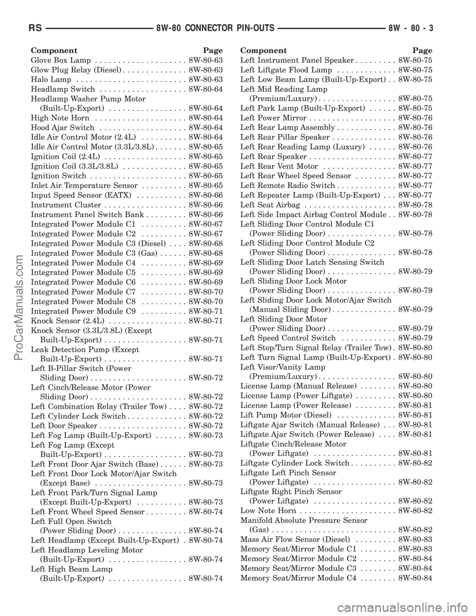
Component Page
Glove Box Lamp.................... 8W-80-63
Glow Plug Relay (Diesel).............. 8W-80-63
Halo Lamp........................ 8W-80-63
Headlamp Switch................... 8W-80-64
Headlamp Washer Pump Motor
(Built-Up-Export)................. 8W-80-64
High Note Horn.................... 8W-80-64
Hood Ajar Switch................... 8W-80-64
Idle Air Control Motor (2.4L).......... 8W-80-64
Idle Air Control Motor (3.3L/3.8L)....... 8W-80-65
Ignition Coil (2.4L).................. 8W-80-65
Ignition Coil (3.3L/3.8L).............. 8W-80-65
Ignition Switch..................... 8W-80-65
Inlet Air Temperature Sensor.......... 8W-80-65
Input Speed Sensor (EATX)........... 8W-80-66
Instrument Cluster.................. 8W-80-66
Instrument Panel Switch Bank......... 8W-80-66
Integrated Power Module C1.......... 8W-80-67
Integrated Power Module C2.......... 8W-80-67
Integrated Power Module C3 (Diesel).... 8W-80-68
Integrated Power Module C3 (Gas)...... 8W-80-68
Integrated Power Module C4.......... 8W-80-69
Integrated Power Module C5.......... 8W-80-69
Integrated Power Module C6.......... 8W-80-69
Integrated Power Module C7.......... 8W-80-70
Integrated Power Module C8.......... 8W-80-70
Integrated Power Module C9.......... 8W-80-71
Knock Sensor (2.4L)................. 8W-80-71
Knock Sensor (3.3L/3.8L) (Except
Built-Up-Export).................. 8W-80-71
Leak Detection Pump (Except
Built-Up-Export).................. 8W-80-71
Left B-Pillar Switch (Power
Sliding Door)..................... 8W-80-72
Left Cinch/Release Motor (Power
Sliding Door)..................... 8W-80-72
Left Combination Relay (Trailer Tow).... 8W-80-72
Left Cylinder Lock Switch............. 8W-80-72
Left Door Speaker................... 8W-80-72
Left Fog Lamp (Built-Up-Export)....... 8W-80-73
Left Fog Lamp (Except
Built-Up-Export).................. 8W-80-73
Left Front Door Ajar Switch (Base)...... 8W-80-73
Left Front Door Lock Motor/Ajar Switch
(Except Base).................... 8W-80-73
Left Front Park/Turn Signal Lamp
(Except Built-Up-Export)........... 8W-80-73
Left Front Wheel Speed Sensor......... 8W-80-74
Left Full Open Switch
(Power Sliding Door)............... 8W-80-74
Left Headlamp (Except Built-Up-Export) . 8W-80-74
Left Headlamp Leveling Motor
(Built-Up-Export)................. 8W-80-74
Left High Beam Lamp
(Built-Up-Export)................. 8W-80-74Component Page
Left Instrument Panel Speaker......... 8W-80-75
Left Liftgate Flood Lamp............. 8W-80-75
Left Low Beam Lamp (Built-Up-Export) . . 8W-80-75
Left Mid Reading Lamp
(Premium/Luxury)................. 8W-80-75
Left Park Lamp (Built-Up-Export)...... 8W-80-75
Left Power Mirror................... 8W-80-76
Left Rear Lamp Assembly............. 8W-80-76
Left Rear Pillar Speaker.............. 8W-80-76
Left Rear Reading Lamp (Luxury)...... 8W-80-76
Left Rear Speaker................... 8W-80-77
Left Rear Vent Motor................ 8W-80-77
Left Rear Wheel Speed Sensor......... 8W-80-77
Left Remote Radio Switch............. 8W-80-77
Left Repeater Lamp (Built-Up-Export) . . . 8W-80-77
Left Seat Airbag.................... 8W-80-78
Left Side Impact Airbag Control Module . . 8W-80-78
Left Sliding Door Control Module C1
(Power Sliding Door)............... 8W-80-78
Left Sliding Door Control Module C2
(Power Sliding Door)............... 8W-80-78
Left Sliding Door Latch Sensing Switch
(Power Sliding Door)............... 8W-80-79
Left Sliding Door Lock Motor
(Power Sliding Door)............... 8W-80-79
Left Sliding Door Lock Motor/Ajar Switch
(Manual Sliding Door).............. 8W-80-79
Left Sliding Door Motor
(Power Sliding Door)............... 8W-80-79
Left Speed Control Switch............ 8W-80-79
Left Stop/Turn Signal Relay (Trailer Tow) . 8W-80-80
Left Turn Signal Lamp (Built-Up-Export) . 8W-80-80
Left Visor/Vanity Lamp
(Premium/Luxury)................. 8W-80-80
License Lamp (Manual Release)........ 8W-80-80
License Lamp (Power Liftgate)......... 8W-80-80
License Lamp (Power Release)......... 8W-80-81
Lift Pump Motor (Diesel)............. 8W-80-81
Liftgate Ajar Switch (Manual Release) . . . 8W-80-81
Liftgate Ajar Switch (Power Release).... 8W-80-81
Liftgate Cinch/Release Motor
(Power Liftgate).................. 8W-80-81
Liftgate Cylinder Lock Switch.......... 8W-80-82
Liftgate Left Pinch Sensor
(Power Liftgate).................. 8W-80-82
Liftgate Right Pinch Sensor
(Power Liftgate).................. 8W-80-82
Low Note Horn..................... 8W-80-82
Manifold Absolute Pressure Sensor
(Gas)........................... 8W-80-82
Mass Air Flow Sensor (Diesel)......... 8W-80-83
Memory Seat/Mirror Module C1........ 8W-80-83
Memory Seat/Mirror Module C2........ 8W-80-84
Memory Seat/Mirror Module C3........ 8W-80-84
Memory Seat/Mirror Module C4........ 8W-80-84
RS8W-80 CONNECTOR PIN-OUTS8W-80-3
ProCarManuals.com
Page 1043 of 2399
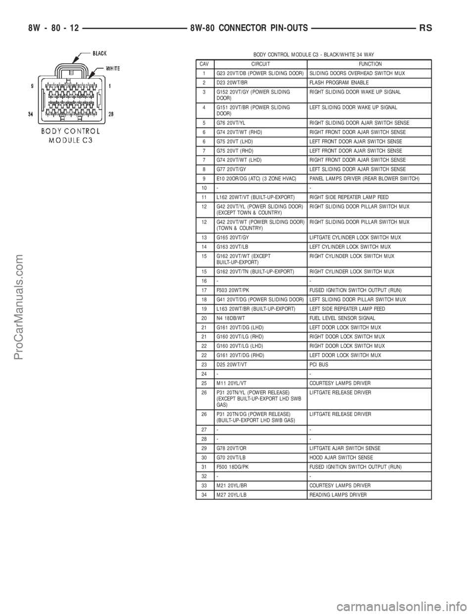
BODY CONTROL MODULE C3 - BLACK/WHITE 34 WAY
CAV CIRCUIT FUNCTION
1 G23 20VT/DB (POWER SLIDING DOOR) SLIDING DOORS OVERHEAD SWITCH MUX
2 D23 20WT/BR FLASH PROGRAM ENABLE
3 G152 20VT/GY (POWER SLIDING
DOOR)RIGHT SLIDING DOOR WAKE UP SIGNAL
4 G151 20VT/BR (POWER SLIDING
DOOR)LEFT SLIDING DOOR WAKE UP SIGNAL
5 G76 20VT/YL RIGHT SLIDING DOOR AJAR SWITCH SENSE
6 G74 20VT/WT (RHD) RIGHT FRONT DOOR AJAR SWITCH SENSE
6 G75 20VT (LHD) LEFT FRONT DOOR AJAR SWITCH SENSE
7 G75 20VT (RHD) LEFT FRONT DOOR AJAR SWITCH SENSE
7 G74 20VT/WT (LHD) RIGHT FRONT DOOR AJAR SWITCH SENSE
8 G77 20VT/GY LEFT SLIDING DOOR AJAR SWITCH SENSE
9 E10 20OR/DG (ATC) (3 ZONE HVAC) PANEL LAMPS DRIVER (REAR BLOWER SWITCH)
10 - -
11 L162 20WT/VT (BUILT-UP-EXPORT) RIGHT SIDE REPEATER LAMP FEED
12 G42 20VT/YL (POWER SLIDING DOOR)
(EXCEPT TOWN & COUNTRY)RIGHT SLIDING DOOR PILLAR SWITCH MUX
12 G42 20VT/WT (POWER SLIDING DOOR)
(TOWN & COUNTRY)RIGHT SLIDING DOOR PILLAR SWITCH MUX
13 G165 20VT/GY LIFTGATE CYLINDER LOCK SWITCH MUX
14 G163 20VT/LB LEFT CYLINDER LOCK SWITCH MUX
15 G162 20VT/WT (EXCEPT
BUILT-UP-EXPORT)RIGHT CYLINDER LOCK SWITCH MUX
15 G162 20VT/TN (BUILT-UP-EXPORT) RIGHT CYLINDER LOCK SWITCH MUX
16 - -
17 F503 20WT/PK FUSED IGNITION SWITCH OUTPUT (RUN)
18 G41 20VT/DG (POWER SLIDING DOOR) LEFT SLIDING DOOR PILLAR SWITCH MUX
19 L163 20WT/BR (BUILT-UP-EXPORT) LEFT SIDE REPEATER LAMP FEED
20 N4 18DB/WT FUEL LEVEL SENSOR SIGNAL
21 G161 20VT/DG (LHD) LEFT DOOR LOCK SWITCH MUX
21 G160 20VT/LG (RHD) RIGHT DOOR LOCK SWITCH MUX
22 G160 20VT/LG (LHD) RIGHT DOOR LOCK SWITCH MUX
22 G161 20VT/DG (RHD) LEFT DOOR LOCK SWITCH MUX
23 D25 20WT/VT PCI BUS
24 - -
25 M11 20YL/VT COURTESY LAMPS DRIVER
26 P31 20TN/YL (POWER RELEASE)
(EXCEPT BUILT-UP-EXPORT LHD SWB
GAS)LIFTGATE RELEASE DRIVER
26 P31 20TN/DG (POWER RELEASE)
(BUILT-UP-EXPORT LHD SWB GAS)LIFTGATE RELEASE DRIVER
27 - -
28 - -
29 G78 20VT/OR LIFTGATE AJAR SWITCH SENSE
30 G70 20VT/LB HOOD AJAR SWITCH SENSE
31 F500 18DG/PK FUSED IGNITION SWITCH OUTPUT (RUN)
32 - -
33 M21 20YL/BR COURTESY LAMPS DRIVER
34 M27 20YL/LB READING LAMPS DRIVER
8W - 80 - 12 8W-80 CONNECTOR PIN-OUTSRS
ProCarManuals.com
Page 1152 of 2399
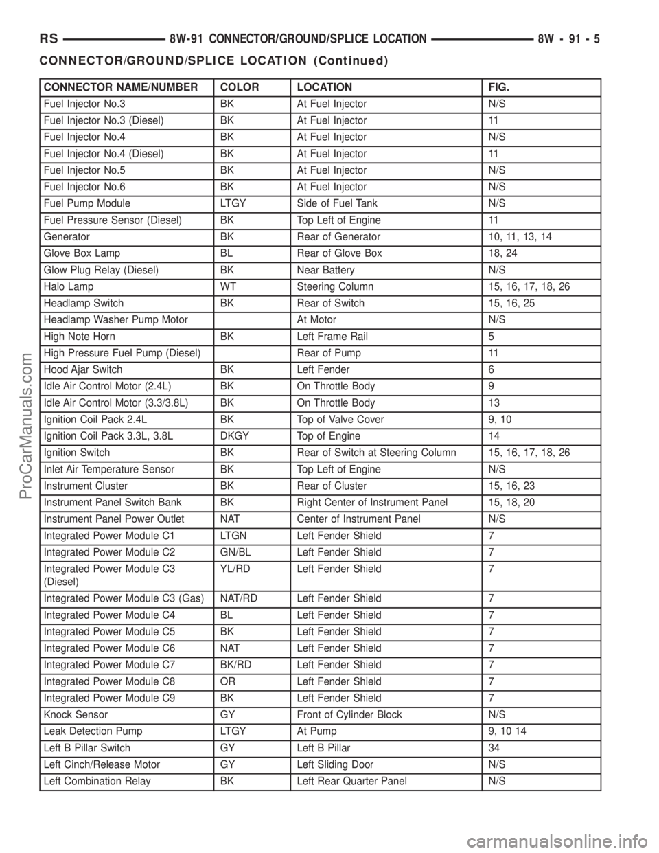
CONNECTOR NAME/NUMBER COLOR LOCATION FIG.
Fuel Injector No.3 BK At Fuel Injector N/S
Fuel Injector No.3 (Diesel) BK At Fuel Injector 11
Fuel Injector No.4 BK At Fuel Injector N/S
Fuel Injector No.4 (Diesel) BK At Fuel Injector 11
Fuel Injector No.5 BK At Fuel Injector N/S
Fuel Injector No.6 BK At Fuel Injector N/S
Fuel Pump Module LTGY Side of Fuel Tank N/S
Fuel Pressure Sensor (Diesel) BK Top Left of Engine 11
Generator BK Rear of Generator 10, 11, 13, 14
Glove Box Lamp BL Rear of Glove Box 18, 24
Glow Plug Relay (Diesel) BK Near Battery N/S
Halo Lamp WT Steering Column 15, 16, 17, 18, 26
Headlamp Switch BK Rear of Switch 15, 16, 25
Headlamp Washer Pump Motor At Motor N/S
High Note Horn BK Left Frame Rail 5
High Pressure Fuel Pump (Diesel) Rear of Pump 11
Hood Ajar Switch BK Left Fender 6
Idle Air Control Motor (2.4L) BK On Throttle Body 9
Idle Air Control Motor (3.3/3.8L) BK On Throttle Body 13
Ignition Coil Pack 2.4L BK Top of Valve Cover 9, 10
Ignition Coil Pack 3.3L, 3.8L DKGY Top of Engine 14
Ignition Switch BK Rear of Switch at Steering Column 15, 16, 17, 18, 26
Inlet Air Temperature Sensor BK Top Left of Engine N/S
Instrument Cluster BK Rear of Cluster 15, 16, 23
Instrument Panel Switch Bank BK Right Center of Instrument Panel 15, 18, 20
Instrument Panel Power Outlet NAT Center of Instrument Panel N/S
Integrated Power Module C1 LTGN Left Fender Shield 7
Integrated Power Module C2 GN/BL Left Fender Shield 7
Integrated Power Module C3
(Diesel)YL/RD Left Fender Shield 7
Integrated Power Module C3 (Gas) NAT/RD Left Fender Shield 7
Integrated Power Module C4 BL Left Fender Shield 7
Integrated Power Module C5 BK Left Fender Shield 7
Integrated Power Module C6 NAT Left Fender Shield 7
Integrated Power Module C7 BK/RD Left Fender Shield 7
Integrated Power Module C8 OR Left Fender Shield 7
Integrated Power Module C9 BK Left Fender Shield 7
Knock Sensor GY Front of Cylinder Block N/S
Leak Detection Pump LTGY At Pump 9, 10 14
Left B Pillar Switch GY Left B Pillar 34
Left Cinch/Release Motor GY Left Sliding Door N/S
Left Combination Relay BK Left Rear Quarter Panel N/S
RS8W-91 CONNECTOR/GROUND/SPLICE LOCATION8W-91-5
CONNECTOR/GROUND/SPLICE LOCATION (Continued)
ProCarManuals.com
Page 1440 of 2399
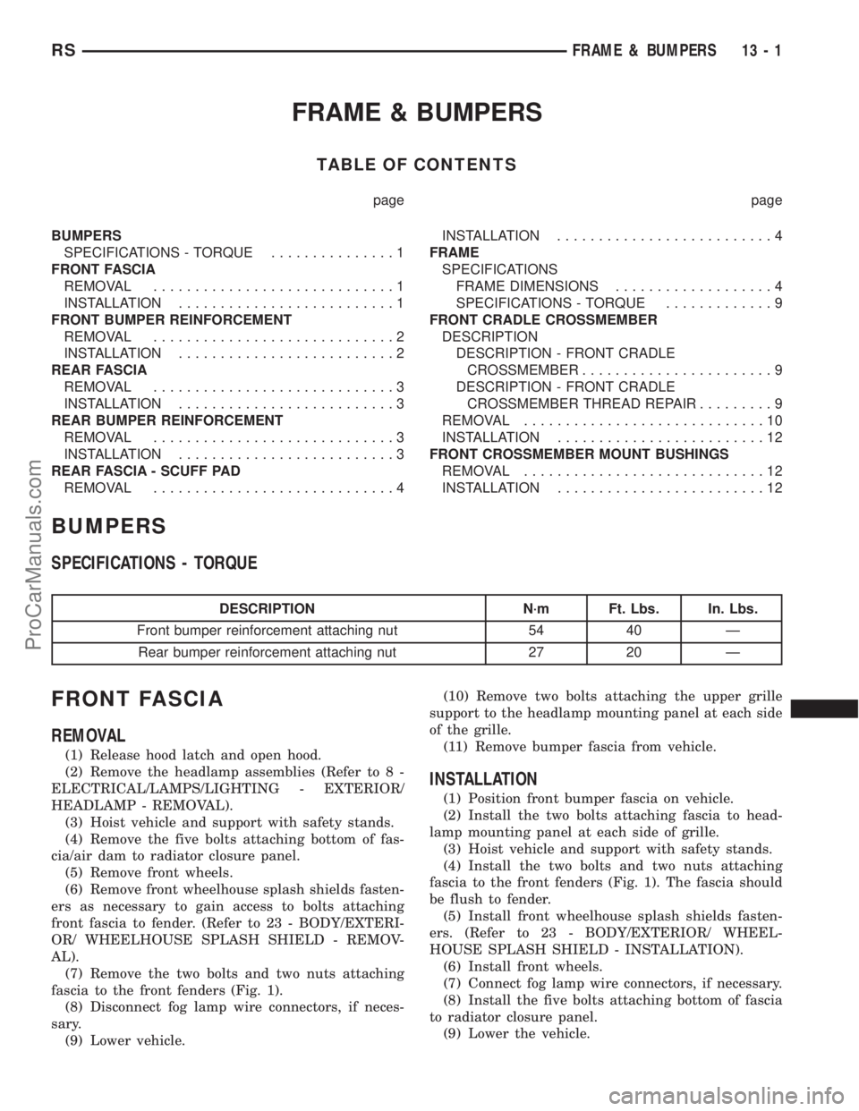
FRAME & BUMPERS
TABLE OF CONTENTS
page page
BUMPERS
SPECIFICATIONS - TORQUE...............1
FRONT FASCIA
REMOVAL.............................1
INSTALLATION..........................1
FRONT BUMPER REINFORCEMENT
REMOVAL.............................2
INSTALLATION..........................2
REAR FASCIA
REMOVAL.............................3
INSTALLATION..........................3
REAR BUMPER REINFORCEMENT
REMOVAL.............................3
INSTALLATION..........................3
REAR FASCIA - SCUFF PAD
REMOVAL.............................4INSTALLATION..........................4
FRAME
SPECIFICATIONS
FRAME DIMENSIONS...................4
SPECIFICATIONS - TORQUE.............9
FRONT CRADLE CROSSMEMBER
DESCRIPTION
DESCRIPTION - FRONT CRADLE
CROSSMEMBER.......................9
DESCRIPTION - FRONT CRADLE
CROSSMEMBER THREAD REPAIR.........9
REMOVAL.............................10
INSTALLATION.........................12
FRONT CROSSMEMBER MOUNT BUSHINGS
REMOVAL.............................12
INSTALLATION.........................12
BUMPERS
SPECIFICATIONS - TORQUE
DESCRIPTION N´m Ft. Lbs. In. Lbs.
Front bumper reinforcement attaching nut 54 40 Ð
Rear bumper reinforcement attaching nut 27 20 Ð
FRONT FASCIA
REMOVAL
(1) Release hood latch and open hood.
(2) Remove the headlamp assemblies (Refer to 8 -
ELECTRICAL/LAMPS/LIGHTING - EXTERIOR/
HEADLAMP - REMOVAL).
(3) Hoist vehicle and support with safety stands.
(4) Remove the five bolts attaching bottom of fas-
cia/air dam to radiator closure panel.
(5) Remove front wheels.
(6) Remove front wheelhouse splash shields fasten-
ers as necessary to gain access to bolts attaching
front fascia to fender. (Refer to 23 - BODY/EXTERI-
OR/ WHEELHOUSE SPLASH SHIELD - REMOV-
AL).
(7) Remove the two bolts and two nuts attaching
fascia to the front fenders (Fig. 1).
(8) Disconnect fog lamp wire connectors, if neces-
sary.
(9) Lower vehicle.(10) Remove two bolts attaching the upper grille
support to the headlamp mounting panel at each side
of the grille.
(11) Remove bumper fascia from vehicle.
INSTALLATION
(1) Position front bumper fascia on vehicle.
(2) Install the two bolts attaching fascia to head-
lamp mounting panel at each side of grille.
(3) Hoist vehicle and support with safety stands.
(4) Install the two bolts and two nuts attaching
fascia to the front fenders (Fig. 1). The fascia should
be flush to fender.
(5) Install front wheelhouse splash shields fasten-
ers. (Refer to 23 - BODY/EXTERIOR/ WHEEL-
HOUSE SPLASH SHIELD - INSTALLATION).
(6) Install front wheels.
(7) Connect fog lamp wire connectors, if necessary.
(8) Install the five bolts attaching bottom of fascia
to radiator closure panel.
(9) Lower the vehicle.
RSFRAME & BUMPERS13-1
ProCarManuals.com
Page 1520 of 2399
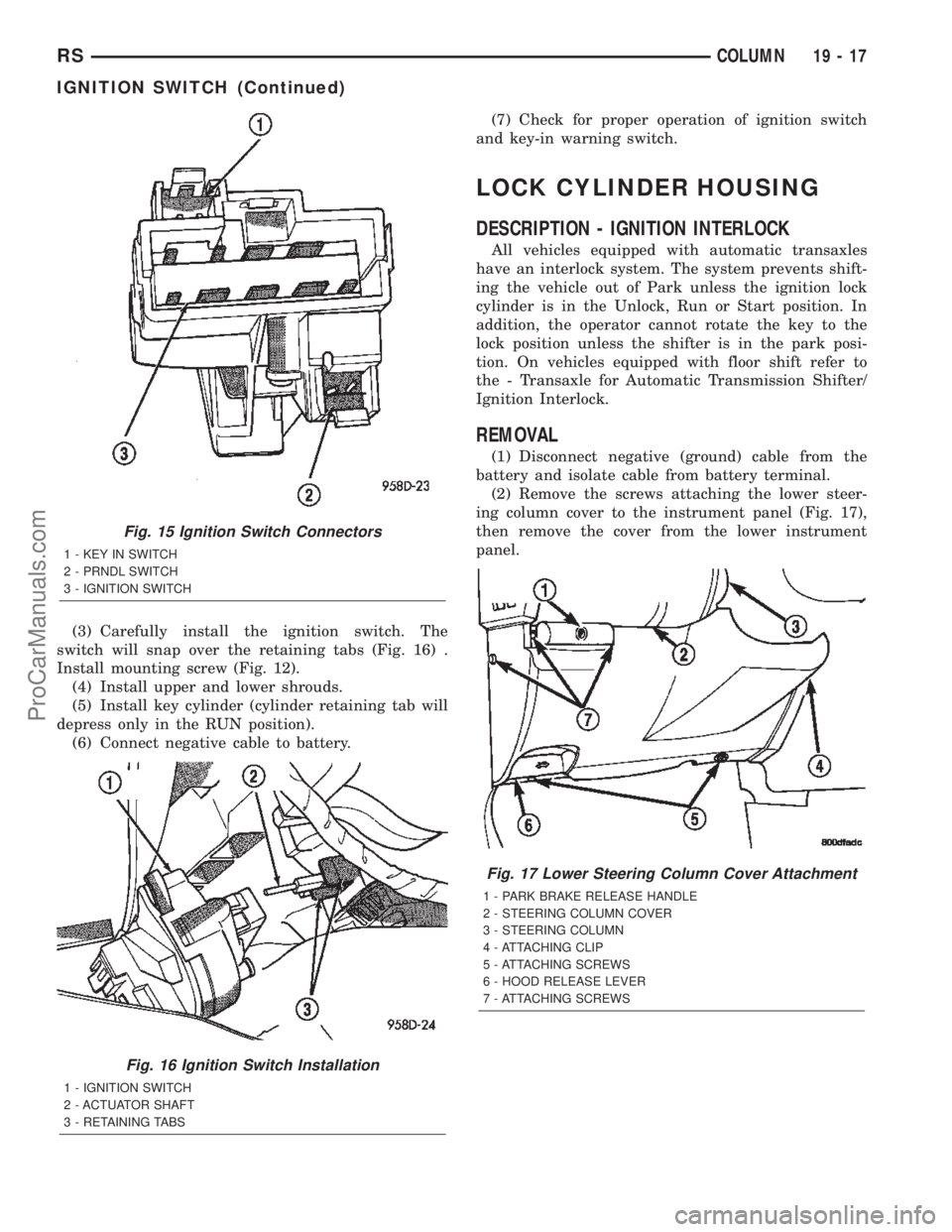
(3) Carefully install the ignition switch. The
switch will snap over the retaining tabs (Fig. 16) .
Install mounting screw (Fig. 12).
(4) Install upper and lower shrouds.
(5) Install key cylinder (cylinder retaining tab will
depress only in the RUN position).
(6) Connect negative cable to battery.(7) Check for proper operation of ignition switch
and key-in warning switch.
LOCK CYLINDER HOUSING
DESCRIPTION - IGNITION INTERLOCK
All vehicles equipped with automatic transaxles
have an interlock system. The system prevents shift-
ing the vehicle out of Park unless the ignition lock
cylinder is in the Unlock, Run or Start position. In
addition, the operator cannot rotate the key to the
lock position unless the shifter is in the park posi-
tion. On vehicles equipped with floor shift refer to
the - Transaxle for Automatic Transmission Shifter/
Ignition Interlock.
REMOVAL
(1) Disconnect negative (ground) cable from the
battery and isolate cable from battery terminal.
(2) Remove the screws attaching the lower steer-
ing column cover to the instrument panel (Fig. 17),
then remove the cover from the lower instrument
panel.
Fig. 15 Ignition Switch Connectors
1 - KEY IN SWITCH
2 - PRNDL SWITCH
3 - IGNITION SWITCH
Fig. 16 Ignition Switch Installation
1 - IGNITION SWITCH
2 - ACTUATOR SHAFT
3 - RETAINING TABS
Fig. 17 Lower Steering Column Cover Attachment
1 - PARK BRAKE RELEASE HANDLE
2 - STEERING COLUMN COVER
3 - STEERING COLUMN
4 - ATTACHING CLIP
5 - ATTACHING SCREWS
6 - HOOD RELEASE LEVER
7 - ATTACHING SCREWS
RSCOLUMN19-17
IGNITION SWITCH (Continued)
ProCarManuals.com