2002 CHRYSLER CARAVAN flat tire
[x] Cancel search: flat tirePage 652 of 2399

(12) Disconnect the reservoir from the body mount
by raising the reservoir upward slightly and then
down so that the reservoir filler neck and front
washer hose pull through the opening in the front
fender side shield.
(13) Remove pump from reservoir by pulling pump
upper retention tab away from reservoir cavity and
then lifting pump up from mounting grommet. Do
not damage reservoir/pump sealing surface or punc-
ture reservoir during removal.
(14) Remove pump grommet and discard.
INSTALLATION
(1) Use new grommet when installing a new pump
assembly.
(2) Assure pump upper retention tab is pressed
into reservoir slot and that pump is rotated flat
against the reservoir and that pump connector is fac-
ing up in the fully seated position. Assure the pump
is aligned to and fully seated in the reservoir cavity.
(3) Push filler neck and front washer hose through
the opening in the front fender side shield. Connect
the reservoir to the body mount by lowering the res-
ervoir down.
(4) Install the two reservoir mounting screws.
Torque screws to 8.5 - 11.3 N´m (75 - 100 in. lbs.).
(5) Connect the electrical body harness connectors
to the washer pump motors and the fluid level sen-
sor. Slide the red lock on the connector to the closed
or locked position.
(6) Assure that washer hose is properly routed to
prevent pinching and possible inoperative washers.
(7) Connect the left right front wheelhouse splash
shield and move aside (Refer to 23 - BODY/EXTERI-
OR/WHEELHOUSE SPLASH SHIELD - INSTALLA-
TION).
(8) Install the right front wheel and tire assembly
(Refer to 22 - TIRES/WHEELS - INSTALLATION).
(9) lower vehicle from hoist or jack stands.
(10) Install the filler tube screw. Torque screw to
8.5 - 11.3 N´m (75 - 100 in. lbs.).
(11) Connect the washer hose to the hose clip
located on the front fender side shield.
(12) Connect the washer hose at the in-line con-
nector forward of the cowl grille.(13) Install the engine fresh air housing inside the
engine compartment (Refer to 9 - ENGINE/AIR
INTAKE SYSTEM/AIR CLEANER HOUSING -
INSTALLATION).
(14) Connect the battery negative cable.
(15) Verify system operation.
REAR WIPER ARM
REMOVAL
(1) Lift and hold wiper blade away from rear win-
dow.
(2) Lift lock holding wiper arm to wiper pivot
upward.
(3) Allow wiper arm to rest against lock.
(4) Pull wiper from pivot by rocking back and forth
(Fig. 5).
INSTALLATION
(1) Position arm on pivot.
(2) Pull up on arm and release lock
(3) Allow wiper arm to rest on rear window.
Fig. 5 REAR WIPER ARM
1 - LOCK
2 - WIPER BLADE
3 - REAR WIPER ARM
RSWIPERS/WASHERS8R-15
REAR WASHER PUMP MOTOR (Continued)
ProCarManuals.com
Page 654 of 2399

(6) Hoist and support vehicle on hoist or jack
stands.
(7) Remove the right front wheel and tire assembly
(Refer to 22 - TIRES/WHEELS - REMOVAL).
(8) Disconnect the left right front wheelhouse
splash shield and move aside (Refer to 23 - BODY/
EXTERIOR/WHEELHOUSE SPLASH SHIELD -
REMOVAL).
(9) Drain washer fluid from the reservoir and into
a suitable clean container. This can be done by dis-
connecting the windshield washer hose from the
front (outboard) washer pump and allowing the
washer fluid to drain into a container through a tem-
porary jumper hose connected to the front washer
pump.
(10) Disconnect the electrical body harness connec-
tors to the washer pump motors and the fluid level
sensor. Slide the red lock on the connector to the
release position, then, depress the black tab and pull
the connector off the pump or sensor.
(11) Remove the two reservoir mounting screws.
(12) Disconnect the reservoir from the body mount
by raising the reservoir upward slightly and then
down so that the reservoir filler neck and front
washer hose pull through the opening in the front
fender side shield.
(13) Remove the sensor from reservoir by using a
side foot to gently pry the sensor from the body of
the reservoir. Do not damage the reservoir/sensor
sealing surface or puncture reservoir during removal.
CAUTION: To avoid damage to the sensor, assure
the reservoir is in an upright position before remov-
ing the sensor from the reservoir. Do not rotate the
sensor during removal.
INSTALLATION
(1) Use a new grommet when installing a new sen-
sor assembly.
(2) Assure that the flat of the sensor is aligned
under the ridge of the reservoir and that the sensor
connector is facing down in the fully seated position.
This will allow for proper operation of the sensor
float switch.
(3) Push filler neck and front washer hose through
the opening in the front fender side shield. Connect
the reservoir to the body mount by lowering the res-
ervoir down.
(4) Install the two reservoir mounting screws.
Torque screws to 8.5 - 11.3 N´m (75 - 100 in. lbs.).(5) Connect the electrical body harness connectors
to the washer pump motors and the fluid level sen-
sor. Slide the red lock on the connector to the closed
or locked position.
(6) Assure that washer hose is properly routed to
prevent pinching and possible inoperative washers.
(7) Connect the left right front wheelhouse splash
shield and move aside (Refer to 23 - BODY/EXTERI-
OR/WHEELHOUSE SPLASH SHIELD - INSTALLA-
TION).
(8) Install the right front wheel and tire assembly
(Refer to 22 - TIRES/WHEELS - INSTALLATION).
(9) lower vehicle from hoist or jack stands.
(10) Install the filler tube screw. Torque screw to
8.5 - 11.3 N´m (75 - 100 in. lbs.).
(11) Connect the washer hose to the hose clip
located on the front fender side shield.
(12) Connect the washer hose at the in-line con-
nector forward of the cowl grille.
(13) Install the engine fresh air housing inside the
engine compartment (Refer to 9 - ENGINE/AIR
INTAKE SYSTEM/AIR CLEANER HOUSING -
INSTALLATION).
(14) Connect the battery negative cable.
(15) Verify system operation.
WASHER HOSES
REMOVAL
(1) Remove washer reservoir from vehicle (Refer to
8 - ELECTRICAL/WIPERS/WASHERS/WASHER
RESERVOIR - REMOVAL).
(2) Disconnect washer hose front the reservoir cav-
ity.
(3) Disconnect the washer hose from the reservoir
pump.
(4) Remove parts as necessary to replace washer
hose (engine compartment, interior components, etc.).
INSTALLATION
(1) Install parts as necessary to after replacing
washer hose (engine compartment, interior compo-
nents, etc.).
(2) Connect the washer hose to the reservoir
pump.
(3) Connect washer hose to the reservoir cavity.
(4) Install the washer reservoir into vehicle (Refer
to 8 - ELECTRICAL/WIPERS/WASHERS/WASHER
RESERVOIR - INSTALLATION).
RSWIPERS/WASHERS8R-17
WASHER FLUID LEVEL SWITCH (Continued)
ProCarManuals.com
Page 1213 of 2399
NOTE: Multi-Layer Steel (MLS) head gaskets require
a scratch free sealing surface.
Only use the following for cleaning gasket surfaces:
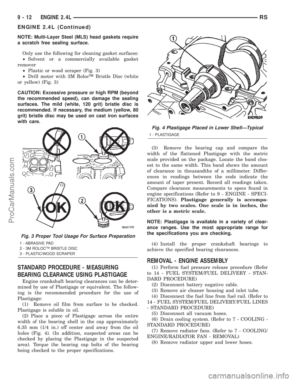
²Solvent or a commercially available gasket
remover
²Plastic or wood scraper (Fig. 3)
²Drill motor with 3M RolocŸ Bristle Disc (white
or yellow) (Fig. 3)
CAUTION: Excessive pressure or high RPM (beyond
the recommended speed), can damage the sealing
surfaces. The mild (white, 120 grit) bristle disc is
recommended. If necessary, the medium (yellow, 80
grit) bristle disc may be used on cast iron surfaces
with care.
STANDARD PROCEDURE - MEASURING
BEARING CLEARANCE USING PLASTIGAGE
Engine crankshaft bearing clearances can be deter-
mined by use of Plastigage or equivalent. The follow-
ing is the recommended procedure for the use of
Plastigage:
(1) Remove oil film from surface to be checked.
Plastigage is soluble in oil.
(2) Place a piece of Plastigage across the entire
width of the bearing shell in the cap approximately
6.35 mm (1/4 in.) off center and away from the oil
holes (Fig. 4). (In addition, suspected areas can be
checked by placing the Plastigage in the suspected
area). Torque the bearing cap bolts of the bearing
being checked to the proper specifications.(3) Remove the bearing cap and compare the
width of the flattened Plastigage with the metric
scale provided on the package. Locate the band clos-
est to the same width. This band shows the amount
of clearance in thousandths of a millimeter. Differ-
ences in readings between the ends indicate the
amount of taper present. Record all readings taken.
Compare clearance measurements to specs found in
engine specifications (Refer to 9 - ENGINE - SPECI-
FICATIONS).Plastigage generally is accompa-
nied by two scales. One scale is in inches, the
other is a metric scale.
NOTE: Plastigage is available in a variety of clear-
ance ranges. Use the most appropriate range for
the specifications you are checking.
(4) Install the proper crankshaft bearings to
achieve the specified bearing clearances.
REMOVAL - ENGINE ASSEMBLY
(1) Perform fuel pressure release procedure (Refer
to 14 - FUEL SYSTEM/FUEL DELIVERY - STAN-
DARD PROCEDURE)
(2) Disconnect battery negative cable.
(3) Remove air cleaner housing and inlet tube.
(4) Disconnect the fuel line from fuel rail. (Refer to
14 - FUEL SYSTEM/FUEL DELIVERY/FUEL LINES
- STANDARD PROCEDURE)
(5) Disconnect all vacuum hoses.
(6) Drain cooling system. (Refer to 7 - COOLING -
STANDARD PROCEDURE)
(7) Remove radiator fans. (Refer to 7 - COOLING/
ENGINE/RADIATOR FAN - REMOVAL)
(8) Remove radiator upper and lower hoses.
Fig. 3 Proper Tool Usage For Surface Preparation
1 - ABRASIVE PAD
2 - 3M ROLOCŸ BRISTLE DISC
3 - PLASTIC/WOOD SCRAPER
Fig. 4 Plastigage Placed in Lower ShellÐTypical
1 - PLASTIGAGE
9 - 12 ENGINE 2.4LRS
ENGINE 2.4L (Continued)
ProCarManuals.com
Page 1285 of 2399
Calibrate the tester according to the manufactur-
er's instructions. The shop air source for testing
should maintain 483 kPa (70 psi) minimum, 1,379
kPa (200 psi) maximum, with 552 kPa (80 psi) rec-
ommended.
Perform the test procedures on each cylinder
according to the tester manufacturer's instructions.
While testing, listen for pressurized air escaping
through the throttle body, tailpipe and oil filler cap
opening. Check for bubbles in the coolant.
All gauge pressure indications should be equal,
with no more than 25% leakage per cylinder.
FOR EXAMPLE:At 552 kPa (80 psi) input pres-
sure, a minimum of 414 kPa (60 psi) should be main-
tained in the cylinder.
STANDARD PROCEDURE
STANDARD PROCEDURE - MEASURING
BEARING CLEARANCE USING PLASTIGAGE
Engine crankshaft bearing clearances can be deter-
mined by use of Plastigage or equivalent. The follow-
ing is the recommended procedure for the use of
Plastigage:
(1) Remove oil film from surface to be checked.
Plastigage is soluble in oil.
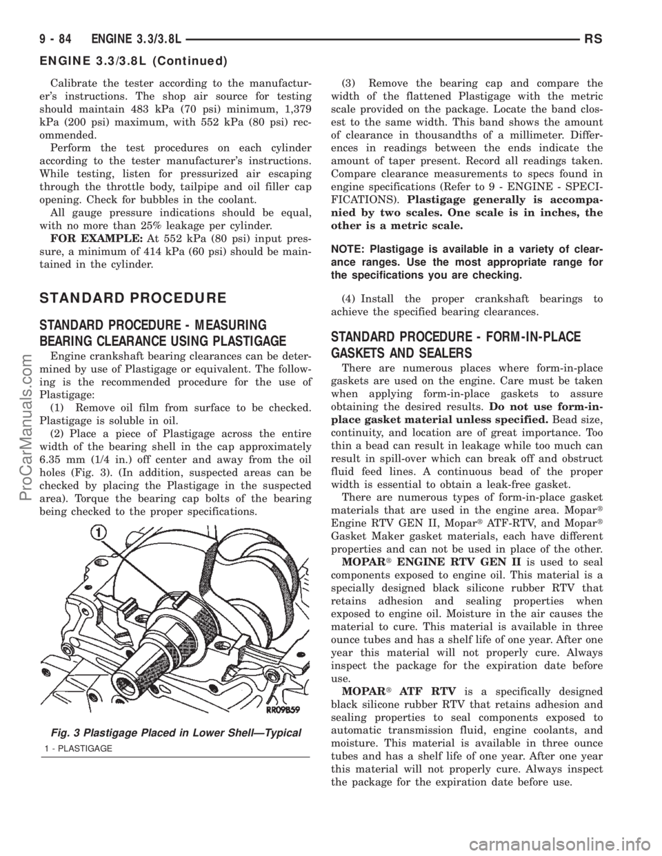
(2) Place a piece of Plastigage across the entire
width of the bearing shell in the cap approximately
6.35 mm (1/4 in.) off center and away from the oil
holes (Fig. 3). (In addition, suspected areas can be
checked by placing the Plastigage in the suspected
area). Torque the bearing cap bolts of the bearing
being checked to the proper specifications.(3) Remove the bearing cap and compare the
width of the flattened Plastigage with the metric
scale provided on the package. Locate the band clos-
est to the same width. This band shows the amount
of clearance in thousandths of a millimeter. Differ-
ences in readings between the ends indicate the
amount of taper present. Record all readings taken.
Compare clearance measurements to specs found in
engine specifications (Refer to 9 - ENGINE - SPECI-
FICATIONS).Plastigage generally is accompa-
nied by two scales. One scale is in inches, the
other is a metric scale.
NOTE: Plastigage is available in a variety of clear-
ance ranges. Use the most appropriate range for
the specifications you are checking.
(4) Install the proper crankshaft bearings to
achieve the specified bearing clearances.
STANDARD PROCEDURE - FORM-IN-PLACE
GASKETS AND SEALERS
There are numerous places where form-in-place
gaskets are used on the engine. Care must be taken
when applying form-in-place gaskets to assure
obtaining the desired results.Do not use form-in-
place gasket material unless specified.Bead size,
continuity, and location are of great importance. Too
thin a bead can result in leakage while too much can
result in spill-over which can break off and obstruct
fluid feed lines. A continuous bead of the proper
width is essential to obtain a leak-free gasket.
There are numerous types of form-in-place gasket
materials that are used in the engine area. Mopart
Engine RTV GEN II, MopartATF-RTV, and Mopart
Gasket Maker gasket materials, each have different
properties and can not be used in place of the other.
MOPARtENGINE RTV GEN IIis used to seal
components exposed to engine oil. This material is a
specially designed black silicone rubber RTV that
retains adhesion and sealing properties when
exposed to engine oil. Moisture in the air causes the
material to cure. This material is available in three
ounce tubes and has a shelf life of one year. After one
year this material will not properly cure. Always
inspect the package for the expiration date before
use.
MOPARtATF RTVis a specifically designed
black silicone rubber RTV that retains adhesion and
sealing properties to seal components exposed to
automatic transmission fluid, engine coolants, and
moisture. This material is available in three ounce
tubes and has a shelf life of one year. After one year
this material will not properly cure. Always inspect
the package for the expiration date before use.
Fig. 3 Plastigage Placed in Lower ShellÐTypical
1 - PLASTIGAGE
9 - 84 ENGINE 3.3/3.8LRS
ENGINE 3.3/3.8L (Continued)
ProCarManuals.com
Page 1317 of 2399
(3) Place a piece of Plastigage across the entire
width of the bearing shell in the bearing cap approx-
imately 6.35 mm (1/4 in.) off center and away from
the oil hole. In addition, suspect areas can be
checked by placing Plastigage in that area.
(4) Assemble the rod cap with Plastigage in place.
Tighten the rod cap to the specified torque.Do not
rotate the crankshaft while assembling the cap
or the Plastigage may be smeared, giving inac-
curate results.
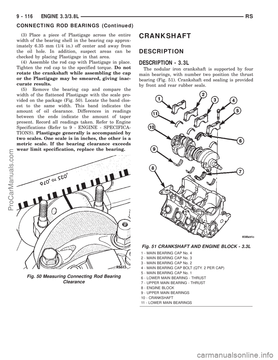
(5) Remove the bearing cap and compare the
width of the flattened Plastigage with the scale pro-
vided on the package (Fig. 50). Locate the band clos-
est to the same width. This band indicates the
amount of oil clearance. Differences in readings
between the ends indicate the amount of taper
present. Record all readings taken. Refer to Engine
Specifications (Refer to 9 - ENGINE - SPECIFICA-
TIONS).Plastigage generally is accompanied by
two scales. One scale is in inches, the other is a
metric scale. If the bearing clearance exceeds
wear limit specification, replace the bearing.CRANKSHAFT
DESCRIPTION
DESCRIPTION - 3.3L
The nodular iron crankshaft is supported by four
main bearings, with number two position the thrust
bearing (Fig. 51). Crankshaft end sealing is provided
by front and rear rubber seals.
Fig. 50 Measuring Connecting Rod Bearing
Clearance
Fig. 51 CRANKSHAFT AND ENGINE BLOCK - 3.3L
1 - MAIN BEARING CAP No. 4
2 - MAIN BEARING CAP No. 3
3 - MAIN BEARING CAP No. 2
4 - MAIN BEARING CAP BOLT (QTY. 2 PER CAP)
5 - MAIN BEARING CAP No. 1
6 - LOWER MAIN BEARING - THRUST
7 - UPPER MAIN BEARING - THRUST
8 - ENGINE BLOCK
9 - UPPER MAIN BEARINGS
10 - CRANKSHAFT
11 - LOWER MAIN BEARINGS
9 - 116 ENGINE 3.3/3.8LRS
CONNECTING ROD BEARINGS (Continued)
ProCarManuals.com
Page 1321 of 2399
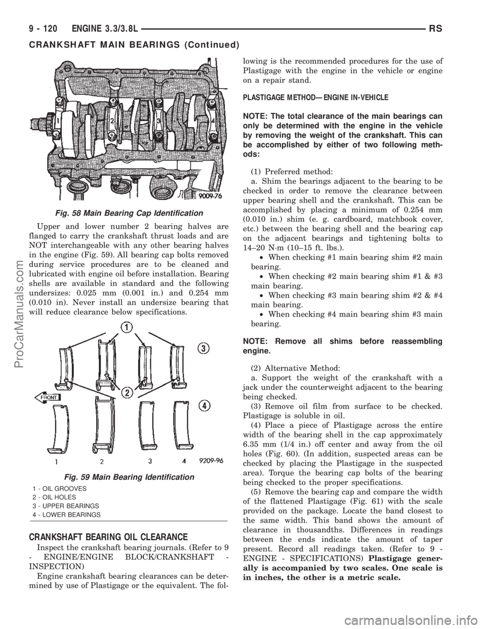
Upper and lower number 2 bearing halves are
flanged to carry the crankshaft thrust loads and are
NOT interchangeable with any other bearing halves
in the engine (Fig. 59). All bearing cap bolts removed
during service procedures are to be cleaned and
lubricated with engine oil before installation. Bearing
shells are available in standard and the following
undersizes: 0.025 mm (0.001 in.) and 0.254 mm
(0.010 in). Never install an undersize bearing that
will reduce clearance below specifications.
CRANKSHAFT BEARING OIL CLEARANCE
Inspect the crankshaft bearing journals. (Refer to 9
- ENGINE/ENGINE BLOCK/CRANKSHAFT -
INSPECTION)
Engine crankshaft bearing clearances can be deter-
mined by use of Plastigage or the equivalent. The fol-lowing is the recommended procedures for the use of
Plastigage with the engine in the vehicle or engine
on a repair stand.
PLASTIGAGE METHODÐENGINE IN-VEHICLE
NOTE: The total clearance of the main bearings can
only be determined with the engine in the vehicle
by removing the weight of the crankshaft. This can
be accomplished by either of two following meth-
ods:
(1) Preferred method:
a. Shim the bearings adjacent to the bearing to be
checked in order to remove the clearance between
upper bearing shell and the crankshaft. This can be
accomplished by placing a minimum of 0.254 mm
(0.010 in.) shim (e. g. cardboard, matchbook cover,
etc.) between the bearing shell and the bearing cap
on the adjacent bearings and tightening bolts to
14±20 N´m (10±15 ft. lbs.).
²When checking #1 main bearing shim #2 main
bearing.
²When checking #2 main bearing shim #1 & #3
main bearing.
²When checking #3 main bearing shim #2 & #4
main bearing.
²When checking #4 main bearing shim #3 main
bearing.
NOTE: Remove all shims before reassembling
engine.
(2) Alternative Method:
a. Support the weight of the crankshaft with a
jack under the counterweight adjacent to the bearing
being checked.
(3) Remove oil film from surface to be checked.
Plastigage is soluble in oil.
(4) Place a piece of Plastigage across the entire
width of the bearing shell in the cap approximately
6.35 mm (1/4 in.) off center and away from the oil
holes (Fig. 60). (In addition, suspected areas can be
checked by placing the Plastigage in the suspected
area). Torque the bearing cap bolts of the bearing
being checked to the proper specifications.
(5) Remove the bearing cap and compare the width
of the flattened Plastigage (Fig. 61) with the scale
provided on the package. Locate the band closest to
the same width. This band shows the amount of
clearance in thousandths. Differences in readings
between the ends indicate the amount of taper
present. Record all readings taken. (Refer to 9 -
ENGINE - SPECIFICATIONS)Plastigage gener-
ally is accompanied by two scales. One scale is
in inches, the other is a metric scale.
Fig. 58 Main Bearing Cap Identification
Fig. 59 Main Bearing Identification
1 - OIL GROOVES
2 - OIL HOLES
3 - UPPER BEARINGS
4 - LOWER BEARINGS
9 - 120 ENGINE 3.3/3.8LRS
CRANKSHAFT MAIN BEARINGS (Continued)
ProCarManuals.com
Page 1509 of 2399
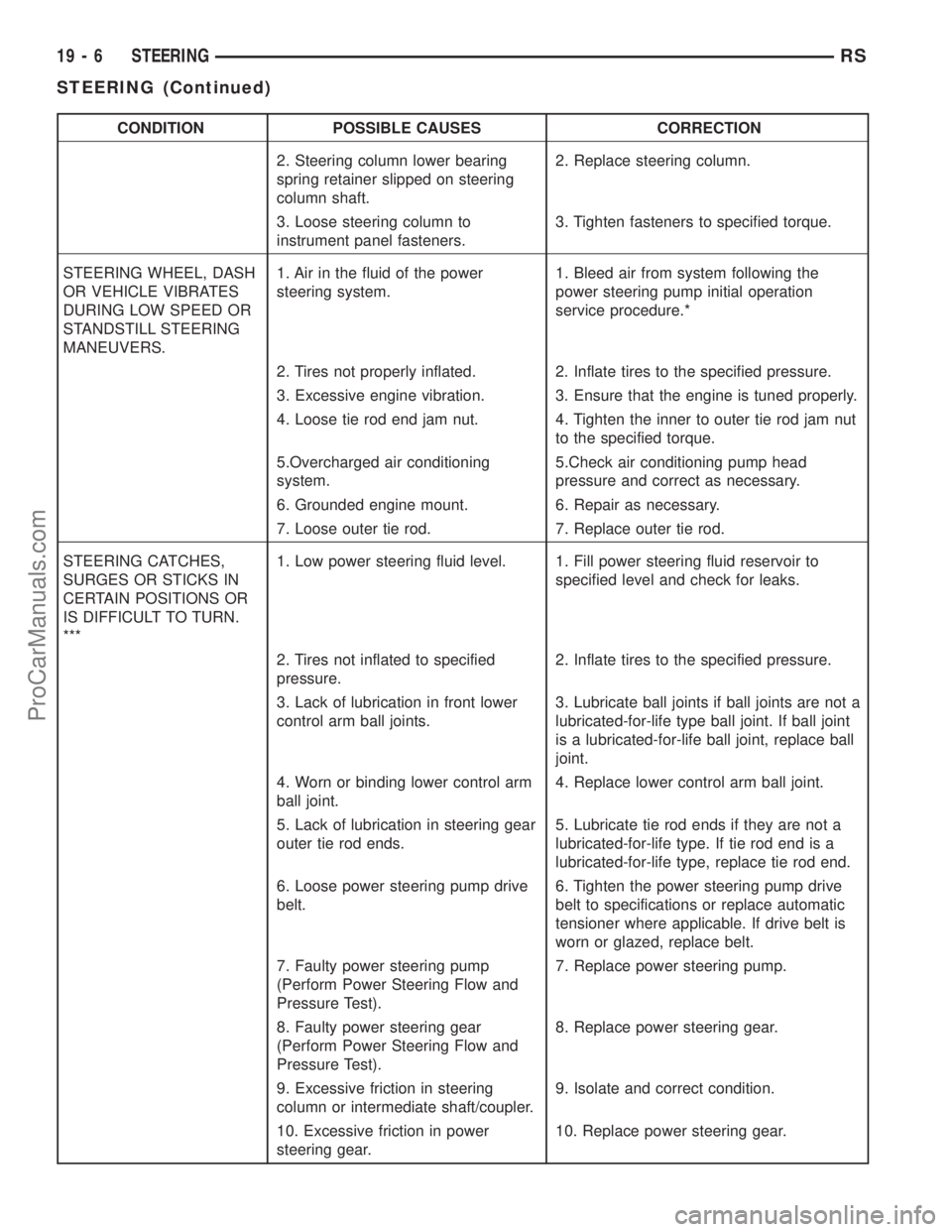
CONDITION POSSIBLE CAUSES CORRECTION
2. Steering column lower bearing
spring retainer slipped on steering
column shaft.2. Replace steering column.
3. Loose steering column to
instrument panel fasteners.3. Tighten fasteners to specified torque.
STEERING WHEEL, DASH
OR VEHICLE VIBRATES
DURING LOW SPEED OR
STANDSTILL STEERING
MANEUVERS.1. Air in the fluid of the power
steering system.1. Bleed air from system following the
power steering pump initial operation
service procedure.*
2. Tires not properly inflated. 2. Inflate tires to the specified pressure.
3. Excessive engine vibration. 3. Ensure that the engine is tuned properly.
4. Loose tie rod end jam nut. 4. Tighten the inner to outer tie rod jam nut
to the specified torque.
5.Overcharged air conditioning
system.5.Check air conditioning pump head
pressure and correct as necessary.
6. Grounded engine mount. 6. Repair as necessary.
7. Loose outer tie rod. 7. Replace outer tie rod.
STEERING CATCHES,
SURGES OR STICKS IN
CERTAIN POSITIONS OR
IS DIFFICULT TO TURN.
***1. Low power steering fluid level. 1. Fill power steering fluid reservoir to
specified level and check for leaks.
2. Tires not inflated to specified
pressure.2. Inflate tires to the specified pressure.
3. Lack of lubrication in front lower
control arm ball joints.3. Lubricate ball joints if ball joints are not a
lubricated-for-life type ball joint. If ball joint
is a lubricated-for-life ball joint, replace ball
joint.
4. Worn or binding lower control arm
ball joint.4. Replace lower control arm ball joint.
5. Lack of lubrication in steering gear
outer tie rod ends.5. Lubricate tie rod ends if they are not a
lubricated-for-life type. If tie rod end is a
lubricated-for-life type, replace tie rod end.
6. Loose power steering pump drive
belt.6. Tighten the power steering pump drive
belt to specifications or replace automatic
tensioner where applicable. If drive belt is
worn or glazed, replace belt.
7. Faulty power steering pump
(Perform Power Steering Flow and
Pressure Test).7. Replace power steering pump.
8. Faulty power steering gear
(Perform Power Steering Flow and
Pressure Test).8. Replace power steering gear.
9. Excessive friction in steering
column or intermediate shaft/coupler.9. Isolate and correct condition.
10. Excessive friction in power
steering gear.10. Replace power steering gear.
19 - 6 STEERINGRS
STEERING (Continued)
ProCarManuals.com
Page 1510 of 2399
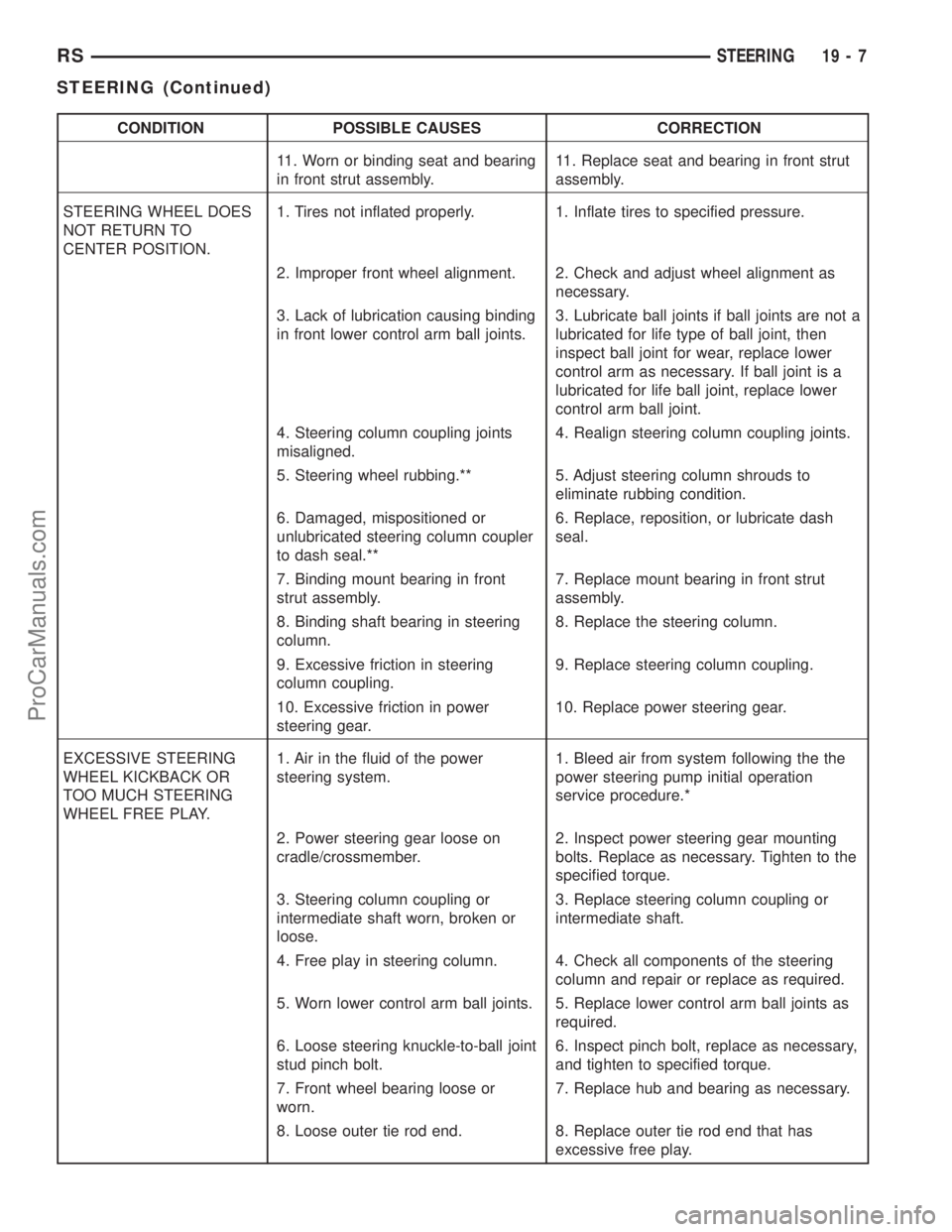
CONDITION POSSIBLE CAUSES CORRECTION
11. Worn or binding seat and bearing
in front strut assembly.11. Replace seat and bearing in front strut
assembly.
STEERING WHEEL DOES
NOT RETURN TO
CENTER POSITION.1. Tires not inflated properly. 1. Inflate tires to specified pressure.
2. Improper front wheel alignment. 2. Check and adjust wheel alignment as
necessary.
3. Lack of lubrication causing binding
in front lower control arm ball joints.3. Lubricate ball joints if ball joints are not a
lubricated for life type of ball joint, then
inspect ball joint for wear, replace lower
control arm as necessary. If ball joint is a
lubricated for life ball joint, replace lower
control arm ball joint.
4. Steering column coupling joints
misaligned.4. Realign steering column coupling joints.
5. Steering wheel rubbing.** 5. Adjust steering column shrouds to
eliminate rubbing condition.
6. Damaged, mispositioned or
unlubricated steering column coupler
to dash seal.**6. Replace, reposition, or lubricate dash
seal.
7. Binding mount bearing in front
strut assembly.7. Replace mount bearing in front strut
assembly.
8. Binding shaft bearing in steering
column.8. Replace the steering column.
9. Excessive friction in steering
column coupling.9. Replace steering column coupling.
10. Excessive friction in power
steering gear.10. Replace power steering gear.
EXCESSIVE STEERING
WHEEL KICKBACK OR
TOO MUCH STEERING
WHEEL FREE PLAY.1. Air in the fluid of the power
steering system.1. Bleed air from system following the the
power steering pump initial operation
service procedure.*
2. Power steering gear loose on
cradle/crossmember.2. Inspect power steering gear mounting
bolts. Replace as necessary. Tighten to the
specified torque.
3. Steering column coupling or
intermediate shaft worn, broken or
loose.3. Replace steering column coupling or
intermediate shaft.
4. Free play in steering column. 4. Check all components of the steering
column and repair or replace as required.
5. Worn lower control arm ball joints. 5. Replace lower control arm ball joints as
required.
6. Loose steering knuckle-to-ball joint
stud pinch bolt.6. Inspect pinch bolt, replace as necessary,
and tighten to specified torque.
7. Front wheel bearing loose or
worn.7. Replace hub and bearing as necessary.
8. Loose outer tie rod end. 8. Replace outer tie rod end that has
excessive free play.
RSSTEERING19-7
STEERING (Continued)
ProCarManuals.com