2002 CHRYSLER CARAVAN audio
[x] Cancel search: audioPage 341 of 2399

interior lamps after 15 minutes after the ignition is
turned off, if they are not turned off by the driver.
²Chime Driver
²Compass/Mini-Trip support.
²Interior Lighting (Courtesy/Reading Lamps)
²BCM Diagnostic Reporting
²Electronic Liftgate Release (with Power Door
Locks)
²Exterior Lighting
²Headlamp Time Delay (with/without Automatic
Headlamps)
²Illuminated Entry
²Fade to Off Interior Lamps - This feature dims
the interior lighting (courtesy lamps) gradually if theBCM does not receive any new inputs that would
cause the interior lamps to remain on.
²Pulse Width Modulated Instrument Panel Dim-
ming
²Door Lock Inhibit - This feature disables the
door lock functions if the key is in the ignition and
either front door is ajar. Pressing the Remote Keyless
Entry (RKE) lock/unlock button under these condi-
tions result in normal lock/unlock activation.
The BCM has the ability to LEARN additional fea-
tures in the vehicle, provided the appropriate switch
input and PCI data bus messages are received. Refer
to the LEARNED FEATURES table.
LEARNED FEATURES
FEATURE LEARNING KEY
CENTRAL LOCKING (WITH VTSS ONLY) DRIVER/PASSENGER KEY CYLINDER SWITCH
PRESENT
AUTOMATIC HEADLAMPS PCI MESSAGE FROM OVERHEAD OR HEADLAMP
SWITCH POSITION (AUTO)
REMOTE KEYLESS ENTRY RKE MESSAGE RECEIVED FROM MODULE
FRONT FOG LAMPS HEADLAMP SWITCH POSITION (PARK W/FRONT
FOG LAMPS)
POWER SLIDING DOOR PCI IFR RECEIVED FROM MODULE
THE BCM HAS FOUR SWITCH INPUTS FOR THE POWER SLIDING DOOR FEATURE; LOCATED IN THE
OVERHEAD CONSOLE ARE THE LEFT AND RIGHT SIDE SLIDING DOOR SWITCHES TO ACTIVATE EITHER
OR BOTH SLIDING DOORS UNDER THE PROPER CONDITIONS. ALSO ARE B-PILLAR SWITCHES LOCATED
ON THE LEFT AND RIGHT B-PILLAR POSTS.
POWER LIFTGATE PCI IFR RECEIVED FROM MODULE
THE BCM HAS ONE LIFTGATE INPUT LOCATED IN THE OVERHEAD CONSOLE.
POWER LOCKOUT SWITCH INPUT
THE BCM HAS ONE LOCKOUT SWITCH INPUT THAT WHEN ENABLED WILL DISABLE THE B-PILLAR
SLIDING DOOR SWITCHES FROM ACTIVATING EITHER SLIDING DOOR WHEN DEPRESSED.
PCI AUDIO SYSTEM PCI MESSAGE RECEIVED FROM MODULE
NOTE: SWAPPING OUT A HIGHLINE RADIO FOR A NON-PCI BUS RADIO (RAS) WILL RESULT IN IMPROPER
HARDWIRE COMMUNICATION BETWEEN THE BCM AND THE NEW RAS RADIO. THE LCD DISPLAY WILL
NOT ILLUMINATE PROPERLY DUE TO THE BCM LEARNING THAT A PCI RADIO EXISTS. HOWEVER, THE
BCM CAN RE-INITIALIZE LEARNED FEATURES VIA THE USE OF THE DRB IIITSCAN TOOL.
REMOTE RADIO CONTROLS REMOTE RADIO SWITCHES PRESENT
VEHICLE THEFT SECURITY DRIVER/PASSENGER DOOR CYLINDER LOCK
SWITCH
MEMORY SEAT AND MIRRORS MEMORY SEAT SWITCH PRESENT AND OR PCI
MESSAGE RECEIVED FROM MEMORY MODULE
ABS W/TRACTION CONTROL PCI MESSAGE RECEIVED FROM CAB
SENTRY KEY IMMOBILIZER SYSTEM PCI MESSAGE RECEIVED FROM SKIM OR VTSS
PRESENT
ADJUSTABLE PEDAL MODULE PCI MESSAGE RECEIVED FROM ADJUSTABLE
PEDAL MODULE (APM)
8E - 4 ELECTRONIC CONTROL MODULESRS
BODY CONTROL MODULE (Continued)
ProCarManuals.com
Page 345 of 2399

²Back-Up switch
²Brake Fluid Level
²B+ Connection Detection
²Engine Crank Signal (Diesel Engine Vehicles)
²Horn Input
²Ignition Switch Start Only
²Ignition Switch Run and Start Only
²Stop Lamp Sense
²Washer Fluid Level
²Windshield Wiper Park
DIAGNOSIS AND TESTING - FRONT CONTROL
MODULE
The Front Control Module (FCM) is a printed cir-
cuit board based module with a on-board micro-pro-
cessor. The FCM interfaces with other electronic
modules in the vehicle via the Programmable Com-
munications Interface (PCI) data bus. In order to
obtain conclusive testing the PCI data bus and all of
the electronic modules that provide inputs to, or
receive outputs from the FCM must be checked. All
PCI communication faults must be resolved prior to
further diagnosing any front control module related
issues.
The FCM was designed to be diagnosed with an
appropriate diagnostic scan tool, such as the DRB
IIIt. The most reliable, efficient, and accurate means
to diagnose the front control module requires the use
of a DRB IIItscan tool and the proper Body Diag-
nostic Procedures manual.
Before any testing of the FCM is attempted, the
battery should be fully charged and all wire harness
and ground connections inspected around the affected
areas on the vehicle.
REMOVAL
(1) Disconnect the positive and negative battery
cables from the battery.
(2) Remove the battery from the vehicle. Refer to
the procedure in Battery Systems.
(3) Using a long flat-bladed screwdriver, gently
twist the Integrated Power Module (IPM) retaining
clip outboard to free the IPM from its mounting
bracket (Fig. 6). Rotate IPM upward to access the
Front Control Module (FCM) retaining screws.
(4) Remove the front control module retaining
screws.
(5) Using both hands, pull the FCM straight from
the IPM assembly to disconnect the 49-way electrical
connector (Fig. 7) and remove the front control mod-
ule from the vehicle.
INSTALLATION
NOTE: Front Control Module must be programmed
to the correct radio EQ curve using the DRB IIIT.This will ensure that the audio system is operating
correctly.
(1) Install the Front Control Module (FCM) in the
Integrated Power Module (IPM) assembly by pushing
the 49-way electrical connector straight in.
(2) Install the FCM retaining screws. Torque the
screws to 1 N´m (7 in. lbs).
(3) Rotate the IPM assembly downward to secure
in mounting bracket.
Fig. 6 REMOVING INTELLIGENT POWER MODULE
Fig. 7 FRONT CONTROL MODULE
1 - FRONT CONTROL MODULE
8E - 8 ELECTRONIC CONTROL MODULESRS
FRONT CONTROL MODULE (Continued)
ProCarManuals.com
Page 658 of 2399

WIRING
TABLE OF CONTENTS
page page
WIRING DIAGRAM INFORMATION....... 8W-01-1
COMPONENT INDEX.................. 8W-02-1
POWER DISTRIBUTION............... 8W-10-1
GROUND DISTRIBUTION.............. 8W-15-1
BUS COMMUNICATIONS.............. 8W-18-1
CHARGING SYSTEM.................. 8W-20-1
STARTING SYSTEM.................. 8W-21-1
FUEL/IGNITION SYSTEM.............. 8W-30-1
TRANSMISSION CONTROL SYSTEM..... 8W-31-1
VEHICLE SPEED CONTROL............ 8W-33-1
ANTILOCK BRAKES................... 8W-35-1
VEHICLE THEFT SECURITY SYSTEM..... 8W-39-1
INSTRUMENT CLUSTER............... 8W-40-1
HORN/CIGAR LIGHTER/POWER OUTLET . . 8W-41-1
AIR CONDITIONING-HEATER........... 8W-42-1
AIRBAG SYSTEM.................... 8W-43-1
INTERIOR LIGHTING.................. 8W-44-1
BODY CONTROL MODULE............. 8W-45-1MESSAGE CENTER................... 8W-46-1
AUDIO SYSTEM..................... 8W-47-1
REAR WINDOW DEFOGGER............ 8W-48-1
OVERHEAD CONSOLE................. 8W-49-1
FRONT LIGHTING.................... 8W-50-1
REAR LIGHTING..................... 8W-51-1
TURN SIGNALS...................... 8W-52-1
WIPERS............................ 8W-53-1
TRAILER TOW....................... 8W-54-1
POWER WINDOWS................... 8W-60-1
POWER DOOR LOCKS................ 8W-61-1
POWER MIRRORS................... 8W-62-1
POWER SEATS...................... 8W-63-1
SPLICE INFORMATION................ 8W-70-1
CONNECTOR PIN-OUTS............... 8W-80-1
CONNECTOR/GROUND/SPLICE
LOCATION........................ 8W-91-1
POWER DISTRIBUTION SYSTEM........ 8W-97-1 RSWIRING
8W-1
ProCarManuals.com
Page 665 of 2399

DESCRIPTION - CIRCUIT FUNCTIONS
All circuits in the diagrams use an alpha/numeric
code to identify the wire and it's function. To identify
which circuit code applies to a system, refer to the
Circuit Identification Code Chart. This chart shows
the main circuits only and does not show the second-
ary codes that may apply to some models.
CIRCUIT IDENTIFICATION CODE CHART
CIRCUIT FUNCTION
A BATTERY FEED
B BRAKE CONTROLS
C CLIMATE CONTROLS
D DIAGNOSTIC CIRCUITS
E DIMMING ILLUMINATION
CIRCUITS
F FUSED CIRCUITS
G MONITORING CIRCUITS
(GAUGES)
H OPEN
I NOT USED
J OPEN
K POWERTRAIN CONTROL
MODULE
L EXTERIOR LIGHTING
M INTERIOR LIGHTING
N NOT USED
O NOT USED
P POWER OPTION (BATTERY
FEED)
Q POWER OPTIONS (IGNITION
FEED)
R PASSIVE RESTRAINT
S SUSPENSION/STEERING
T TRANSMISSION/TRANSAXLE/
TRANSFER CASE
U OPEN
V SPEED CONTROL, WIPER/
WASHER
W OPEN
X AUDIO SYSTEMS
Y OPEN
Z GROUNDS
DESCRIPTION - SECTION IDENTIFICATION AND
INFORMATION
The wiring diagrams are grouped into individual
sections. If a component is most likely found in a par-
ticular group, it will be shown complete (all wires,
connectors, and pins) within that group. For exam-
ple, the Auto Shutdown Relay is most likely to be
found in Group 30, so it is shown there complete. It
can, however, be shown partially in another group if
it contains some associated wiring.
Splice diagrams in Section 8W-70 show the entire
splice and provide references to other sections the
splices serves. Section 8W-70 only contains splice dia-
grams that are not shown in their entirety some-
where else in the wiring diagrams.
Section 8W-80 shows each connector and the cir-
cuits involved with that connector. The connectors
are identified using the name/number on the dia-
gram pages.
WIRING SECTION CHART
GROUP TOPIC
8W-01 thru
8W-09General information and Diagram
Overview
8W-10 thru
8W-19Main Sources of Power and
Vehicle Grounding
8W-20 thru
8W-29Starting and Charging
8W-30 thru
8W-39Powertrain/Drivetrain Systems
8W-40 thru
8W-49Body Electrical items and A/C
8W-50 thru
8W-59Exterior Lighting, Wipers and
Trailer Tow
8W-60 thru
8W-69Power Accessories
8W-70 Splice Information
8W-80 Connector Pin Outs
8W-91 Connector, Ground and Splice
Locations
8W - 01 - 6 8W-01 WIRING DIAGRAM INFORMATIONRS
WIRING DIAGRAM INFORMATION (Continued)
ProCarManuals.com
Page 924 of 2399

8W-47 AUDIO SYSTEM
Component Page
Accessory Relay................... 8W-47-2, 5
Antenna........................... 8W-47-5
Body Control Module............. 8W-47-2, 5, 7
CD Changer....................... 8W-47-11
Clockspring......................... 8W-47-7
Diagnostic Junction Port............. 8W-47-2, 5
Front Cigar Lighter................ 8W-47-2, 5
Front Control Module............. 8W-47-2, 5, 6
Fuse 5........................... 8W-47-2, 5
Fuse 14.......................... 8W-47-2, 6
G202....................... 8W-47-2, 5, 9, 10
Integrated Power Module.......... 8W-47-2, 5, 6
Left Door Speaker................ 8W-47-3, 8, 9Component Page
Left Instrument Panel Speaker........ 8W-47-3, 8
Left Rear Pillar Speaker.............. 8W-47-10
Left Rear Speaker............... 8W-47-4, 6, 10
Left Remote Radio Switch.............. 8W-47-7
Name Brand Speaker Relay............ 8W-47-6
Radio.............. 8W-47-2, 3, 4, 5, 6, 9, 10, 11
Radio Choke........................ 8W-47-6
Right Door Speaker............... 8W-47-3, 8, 9
Right Instrument Panel Speaker...... 8W-47-3, 8
Right Rear Pillar Speaker............. 8W-47-10
Right Rear Speaker.............. 8W-47-4, 6, 10
Right Remote Radio Switch............ 8W-47-7
RS8W-47 AUDIO SYSTEM8W-47-1
ProCarManuals.com
Page 1074 of 2399

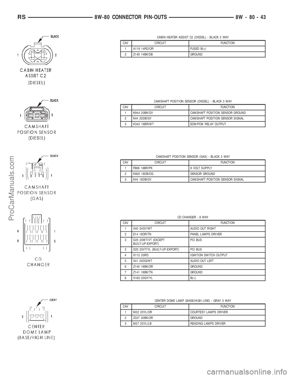
CABIN HEATER ASSIST C2 (DIESEL) - BLACK 2 WAY
CAV CIRCUIT FUNCTION
1 A119 14RD/OR FUSED B(+)
2 Z149 14BK/DB GROUND
CAMSHAFT POSITION SENSOR (DIESEL) - BLACK 3 WAY
CAV CIRCUIT FUNCTION
1 K944 20BK/GY CAMSHAFT POSITION SENSOR GROUND
2 K44 20DB/GY CAMSHAFT POSITION SENSOR SIGNAL
3 K342 16BR/WT ECM/PCM RELAY OUTPUT
CAMSHAFT POSITION SENSOR (GAS) - BLACK 3 WAY
CAV CIRCUIT FUNCTION
1 F888 18BR/PK 8 VOLT SUPPLY
2 K900 18DB/DG SENSOR GROUND
3 K44 18DB/GY CAMSHAFT POSITION SENSOR SIGNAL
CD CHANGER-8WAY
CAV CIRCUIT FUNCTION
1 X40 24GY/WT AUDIO OUT RIGHT
2 E14 18OR/TN PANEL LAMPS DRIVER
3 D25 20WT/VT (EXCEPT
BUILT-UP-EXPORT)PCI BUS
3 D25 20VT/YL (BUILT-UP-EXPORT) PCI BUS
4 X112 20RD IGNITION SWITCH OUTPUT
5 X41 20DG/WT AUDIO OUT LEFT
6 Z140 18BK/OR GROUND
7 Z141 18BK/TN GROUND
8 X160 20GY/YL B(+)
CENTER DOME LAMP (BASE/HIGH LINE) - GRAY 3 WAY
CAV CIRCUIT FUNCTION
1 M22 20YL/OR COURTESY LAMPS DRIVER
2 Z327 20BK/OR GROUND
3 M27 20YL/LB READING LAMPS DRIVER
RS8W-80 CONNECTOR PIN-OUTS8W-80-43
ProCarManuals.com
Page 1129 of 2399

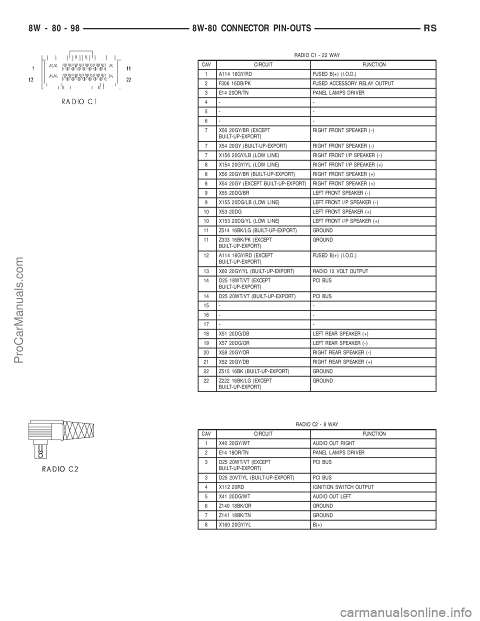
RADIO C1 - 22 WAY
CAV CIRCUIT FUNCTION
1 A114 16GY/RD FUSED B(+) (I.O.D.)
2 F306 16DB/PK FUSED ACCESSORY RELAY OUTPUT
3 E14 20OR/TN PANEL LAMPS DRIVER
4- -
5- -
6- -
7 X56 20GY/BR (EXCEPT
BUILT-UP-EXPORT)RIGHT FRONT SPEAKER (-)
7 X54 20GY (BUILT-UP-EXPORT) RIGHT FRONT SPEAKER (-)
7 X156 20GY/LB (LOW LINE) RIGHT FRONT I/P SPEAKER (-)
8 X154 20GY/YL (LOW LINE) RIGHT FRONT I/P SPEAKER (+)
8 X56 20GY/BR (BUILT-UP-EXPORT) RIGHT FRONT SPEAKER (+)
8 X54 20GY (EXCEPT BUILT-UP-EXPORT) RIGHT FRONT SPEAKER (+)
9 X55 20DG/BR LEFT FRONT SPEAKER (-)
9 X155 20DG/LB (LOW LINE) LEFT FRONT I/P SPEAKER (-)
10 X53 20DG LEFT FRONT SPEAKER (+)
10 X153 20DG/YL (LOW LINE) LEFT FRONT I/P SPEAKER (+)
11 Z514 16BK/LG (BUILT-UP-EXPORT) GROUND
11 Z333 16BK/PK (EXCEPT
BUILT-UP-EXPORT)GROUND
12 A114 16GY/RD (EXCEPT
BUILT-UP-EXPORT)FUSED B(+) (I.O.D.)
13 X60 20GY/YL (BUILT-UP-EXPORT) RADIO 12 VOLT OUTPUT
14 D25 18WT/VT (EXCEPT
BUILT-UP-EXPORT)PCI BUS
14 D25 20WT/VT (BUILT-UP-EXPORT) PCI BUS
15 - -
16 - -
17 - -
18 X51 20DG/DB LEFT REAR SPEAKER (+)
19 X57 20DG/OR LEFT REAR SPEAKER (-)
20 X58 20GY/OR RIGHT REAR SPEAKER (-)
21 X52 20GY/DB RIGHT REAR SPEAKER (+)
22 Z515 16BK (BUILT-UP-EXPORT) GROUND
22 Z222 16BK/LG (EXCEPT
BUILT-UP-EXPORT)GROUND
RADIO C2-8WAY
CAV CIRCUIT FUNCTION
1 X40 20GY/WT AUDIO OUT RIGHT
2 E14 18OR/TN PANEL LAMPS DRIVER
3 D25 20WT/VT (EXCEPT
BUILT-UP-EXPORT)PCI BUS
3 D25 20VT/YL (BUILT-UP-EXPORT) PCI BUS
4 X112 20RD IGNITION SWITCH OUTPUT
5 X41 20DG/WT AUDIO OUT LEFT
6 Z140 18BK/OR GROUND
7 Z141 18BK/TN GROUND
8 X160 20GY/YL B(+)
8W - 80 - 98 8W-80 CONNECTOR PIN-OUTSRS
ProCarManuals.com