2002 CHRYSLER CARAVAN ECU
[x] Cancel search: ECUPage 2279 of 2399
INFRARED TEMPERATURE
SENSOR
DESCRIPTION
The rear infrared temperature sensor consists of
an infrared transducer that is concealed behind the
lens of the rear heater-A/C control in the headliner.
This sensor is used only on models equipped with the
optional Automatic Temperature Control (ATC) heat-
ing and air conditioning system. The rear infrared
temperature sensor is integral to the rear heater-A/C
control. The infrared sensor cannot be adjusted or
repaired and, if faulty or damaged, the rear heater-
A/C control unit must be replaced.
OPERATION
The rear infrared temperature sensor provides an
independent measurement input to the Automatic
Temperature Control (ATC) heater-A/C control mod-
ule that indicates the surface temperature of the rear
seat occupants. By using a surface temperature mea-
surement, rather than an air temperature measure-
ment, the ATC system is able to adjust itself to the
comfort level as perceived by the occupant. This
allows the system to detect and compensate for other
ambient conditions affecting comfort levels, such as
solar heat gain or evaporative heat loss. The ATC
system logic responds to the infrared sensor input by
calculating and adjusting the air flow temperature
and air flow rate needed to properly obtain and
maintain the selected comfort level temperatures for
the rear seat occupants. The ATC heater-A/C control
module continually monitors the infrared sensor cir-
cuit, and will store a Diagnostic Trouble Code (DTC)
for any problem it detects. This DTC information can
be retrieved and the infrared temperature sensor
diagnosed using a DRBIIItscan tool. Refer to the
appropriate diagnostic information.
MODE DOOR ACTUATOR
REMOVAL
(1) Disconnect and isolate the battery negative
cable.
(2) Remove the right quarter trim panel and right
D-pillar trim panel from the quarter inner panel.
(Refer to 23 - BODY/INTERIOR/QUARTER TRIM
PANEL - REMOVAL).
(3) Remove the two screws that secure the top of
the quarter trim panel attaching bracket to the quar-
ter inner panel.
(4) Remove the screw that secures the back of the
rear heater-A/C unit housing to the right D-pillar.(5) Remove the screw that secures the front of the
rear heater-A/C unit housing to the right quarter
inner panel.
(6) Carefully pull the top of the rear heater-A/C
unit housing away from the right quarter inner panel
far enough to reach between the rear heater-A/C unit
housing and the quarter inner panel to access the
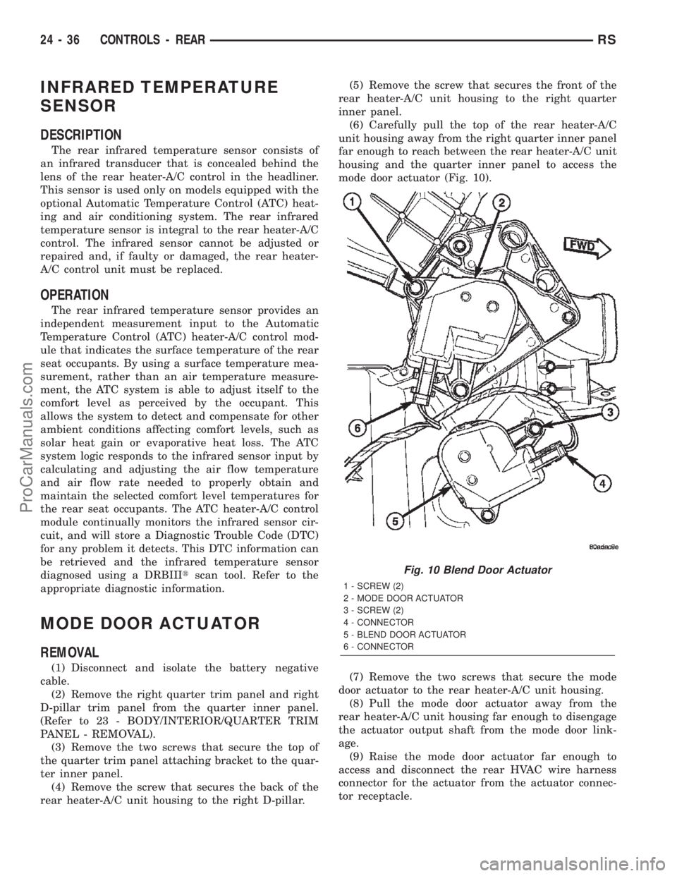
mode door actuator (Fig. 10).
(7) Remove the two screws that secure the mode
door actuator to the rear heater-A/C unit housing.
(8) Pull the mode door actuator away from the
rear heater-A/C unit housing far enough to disengage
the actuator output shaft from the mode door link-
age.
(9) Raise the mode door actuator far enough to
access and disconnect the rear HVAC wire harness
connector for the actuator from the actuator connec-
tor receptacle.
Fig. 10 Blend Door Actuator
1 - SCREW (2)
2 - MODE DOOR ACTUATOR
3 - SCREW (2)
4 - CONNECTOR
5 - BLEND DOOR ACTUATOR
6 - CONNECTOR
24 - 36 CONTROLS - REARRS
ProCarManuals.com
Page 2280 of 2399
(10) Remove the mode door actuator from between
the rear heater-A/C unit housing and the quarter
inner panel.
INSTALLATION
(1) Position the mode door actuator between the
rear heater-A/C unit housing and the quarter inner
panel.
(2) Reconnect the rear HVAC wire harness connec-
tor for the mode door actuator to the actuator connec-
tor receptacle.
(3) Position the mode door actuator onto the rear
heater-A/C unit housing. If necessary, rotate the
actuator slightly to align the splines on the actuator
output shaft with those in the mode door linkage.
(4) Install and tighten the two screws that secure
the mode door actuator to the rear heater-A/C unit
housing. Tighten the screws to 2 N´m (18 in. lbs.).
(5) Push the top of the rear heater-A/C unit hous-
ing back into position against the right quarter inner
panel.
(6) Install and tighten the screw that secures the
front of the rear heater-A/C unit housing to the right
quarter inner panel. Tighten the screw to 11 N´m (97
in. lbs.).
(7) Install and tighten the screw that secures the
back of the rear heater-A/C unit housing to the right
D-pillar. Tighten the screw to 11 N´m (97 in. lbs.).
(8) Install and tighten the two screws that secure
the top of the quarter trim panel attaching bracket to
the quarter inner panel. Tighten the screws to 1.7
N´m (15 in. lbs.).
(9) Reinstall the right quarter trim panel and
right D-pillar trim panel onto the quarter inner
panel. (Refer to 23 - BODY/INTERIOR/QUARTER
TRIM PANEL - INSTALLATION).
(10) Reconnect the battery negative cable.
(11) Perform the heater-A/C control calibration
procedure. (Refer to 24 - HEATING & AIR CONDI-
TIONING/CONTROLS - FRONT/A/C-HEATER CON-
TROL - STANDARD PROCEDURE - HEATER-A/C
CONTROL CALIBRATION).
POWER MODULE
DESCRIPTION
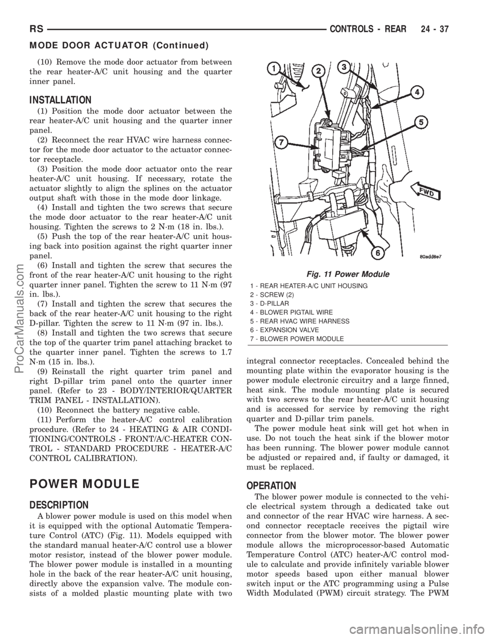
A blower power module is used on this model when
it is equipped with the optional Automatic Tempera-
ture Control (ATC) (Fig. 11). Models equipped with
the standard manual heater-A/C control use a blower
motor resistor, instead of the blower power module.
The blower power module is installed in a mounting
hole in the back of the rear heater-A/C unit housing,
directly above the expansion valve. The module con-
sists of a molded plastic mounting plate with twointegral connector receptacles. Concealed behind the
mounting plate within the evaporator housing is the
power module electronic circuitry and a large finned,
heat sink. The module mounting plate is secured
with two screws to the rear heater-A/C unit housing
and is accessed for service by removing the right
quarter and D-pillar trim panels.
The power module heat sink will get hot when in
use. Do not touch the heat sink if the blower motor
has been running. The blower power module cannot
be adjusted or repaired and, if faulty or damaged, it
must be replaced.
OPERATION
The blower power module is connected to the vehi-
cle electrical system through a dedicated take out
and connector of the rear HVAC wire harness. A sec-
ond connector receptacle receives the pigtail wire
connector from the blower motor. The blower power
module allows the microprocessor-based Automatic
Temperature Control (ATC) heater-A/C control mod-
ule to calculate and provide infinitely variable blower
motor speeds based upon either manual blower
switch input or the ATC programming using a Pulse
Width Modulated (PWM) circuit strategy. The PWM
Fig. 11 Power Module
1 - REAR HEATER-A/C UNIT HOUSING
2 - SCREW (2)
3 - D-PILLAR
4 - BLOWER PIGTAIL WIRE
5 - REAR HVAC WIRE HARNESS
6 - EXPANSION VALVE
7 - BLOWER POWER MODULE
RSCONTROLS - REAR24-37
MODE DOOR ACTUATOR (Continued)
ProCarManuals.com
Page 2281 of 2399
voltage is applied to a comparator circuit which com-
pares the PWM signal voltage to the blower motor
feedback voltage. The resulting output drives the
power module circuitry, which adjusts the voltage
output received from the blower motor relay to
change or maintain the desired blower speed. The
blower power module is diagnosed using a DRBIIIt
scan tool. Refer to the appropriate diagnostic infor-
mation.
REMOVAL
(1) Disconnect and isolate the battery negative
cable.
(2) Remove the right quarter trim panel and right
D-pillar trim panel from the quarter inner panel.
(Refer to 23 - BODY/INTERIOR/QUARTER TRIM
PANEL - REMOVAL).
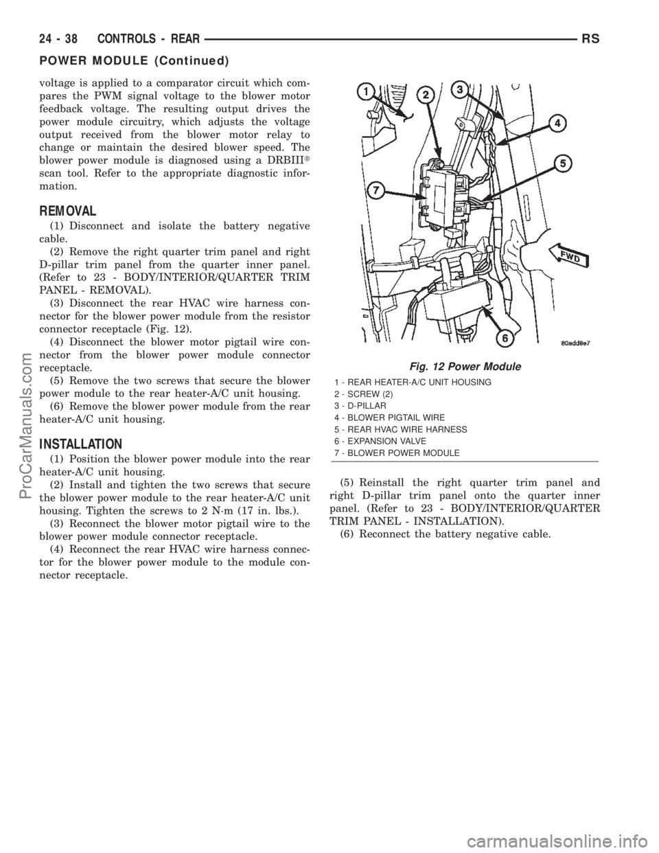
(3) Disconnect the rear HVAC wire harness con-
nector for the blower power module from the resistor
connector receptacle (Fig. 12).
(4) Disconnect the blower motor pigtail wire con-
nector from the blower power module connector
receptacle.
(5) Remove the two screws that secure the blower
power module to the rear heater-A/C unit housing.
(6) Remove the blower power module from the rear
heater-A/C unit housing.
INSTALLATION
(1) Position the blower power module into the rear
heater-A/C unit housing.
(2) Install and tighten the two screws that secure
the blower power module to the rear heater-A/C unit
housing. Tighten the screws to 2 N´m (17 in. lbs.).
(3) Reconnect the blower motor pigtail wire to the
blower power module connector receptacle.
(4) Reconnect the rear HVAC wire harness connec-
tor for the blower power module to the module con-
nector receptacle.(5) Reinstall the right quarter trim panel and
right D-pillar trim panel onto the quarter inner
panel. (Refer to 23 - BODY/INTERIOR/QUARTER
TRIM PANEL - INSTALLATION).
(6) Reconnect the battery negative cable.
Fig. 12 Power Module
1 - REAR HEATER-A/C UNIT HOUSING
2 - SCREW (2)
3 - D-PILLAR
4 - BLOWER PIGTAIL WIRE
5 - REAR HVAC WIRE HARNESS
6 - EXPANSION VALVE
7 - BLOWER POWER MODULE
24 - 38 CONTROLS - REARRS
POWER MODULE (Continued)
ProCarManuals.com
Page 2284 of 2399
or damaged, the instrument panel top cover must be
replaced.
²Demister Outlets- There are two side window
demisters that aid in defogging and defrosting the
front door windows. One demister outlet is located at
each outboard end of the instrument panel top pad,
near the belt line at the A-pillars. The demister out-
lets can be removed from the top pad individually for
service replacement.
²Instrument Panel Outlets- There are five
panel outlets in the instrument panel, one located
near each outboard end of the instrument panel fac-
ing the rear of the vehicle, and three located near the
top of the instrument panel center bezel. On models
with manual temperature control, all five of these
outlets are fully adjustable. On models with Auto-
matic Temperature Control (ATC), the center outlet
in the center bezel has fixed vanes because it also
houses the remote infrared temperature sensors for
the front seat positions. The outboard outlets can be
removed individually for service replacement. The
center bezel outlets are serviced as a gang of three
outlets and, on models with ATC, also includes the
infrared sensors.
²Front Door Rear Outlets- A fully adjustable
outlet located at the rear of each front door trim
panel supplies only cooled air to the intermediate
seat passengers. Air is supplied to these outlets from
the instrument panel through ducts in the doors that
use molded seals at the instrument panel to prevent
air leakage. The door ducts are integral to the front
door trim panels. These outlets also incorporate a red
reflector to improve the safety and visibility of an
opened front door to traffic approaching the vehicle
from the rear at night. These outlets can be removed
from the door trim panels for service replacement.
²Front Floor Outlets- There are two front floor
outlets, one located above each side of the floor panel
center tunnel below the instrument panel. These out-
lets are integral to the front heater-A/C unit distri-
bution housing.
²Rear Floor Outlets- Wide rear floor outlets
located under each front seat have integral, fixed
directional dividers to distribute heated air across
the floor for intermediate seat passengers. These out-
lets are integral to the floor distribution ducts routed
under the front floor carpet from an outlet nozzle on
the bottom of the front heater-A/C unit distribution
housing.
REMOVAL
REMOVAL - CENTER BEZEL OUTLETS
The three outlets located near the top of the
instrument panel center bezel are serviced only as a
set of all three outlets. If the vehicle is equipped withthe optional Automatic Temperature Control (ATC)
system, the center outlet of the three has fixed vanes
and also houses the remote front infrared tempera-
ture sensors.
WARNING: ON VEHICLES EQUIPPED WITH AIR-
BAGS, DISABLE THE AIRBAG SYSTEM BEFORE
ATTEMPTING ANY STEERING WHEEL, STEERING
COLUMN, OR INSTRUMENT PANEL COMPONENT
DIAGNOSIS OR SERVICE. DISCONNECT AND ISO-
LATE THE BATTERY NEGATIVE (GROUND) CABLE,
THEN WAIT TWO MINUTES FOR THE AIRBAG SYS-
TEM CAPACITOR TO DISCHARGE BEFORE PER-
FORMING FURTHER DIAGNOSIS OR SERVICE. THIS
IS THE ONLY SURE WAY TO DISABLE THE AIRBAG
SYSTEM. FAILURE TO TAKE THE PROPER PRE-
CAUTIONS COULD RESULT IN ACCIDENTAL AIR-
BAG DEPLOYMENT AND POSSIBLE PERSONAL
INJURY.
(1) Disconnect and isolate the battery negative
cable.
(2) Remove the center bezel from the instrument
panel. (Refer to 23 - BODY/INSTRUMENT PANEL/
INSTRUMENT PANEL CENTER BEZEL - REMOV-
AL).
(3) Place the center bezel face down on a suitable
work surface. Be certain to take the proper precau-
tions to protect the face of the center bezel from cos-
metic damage.
(4) If the vehicle is equipped with the optional
ATC system, disconnect the ATC remote infrared
temperature sensor jumper harness from the sensor
connector receptacle located on the bottom of the cen-
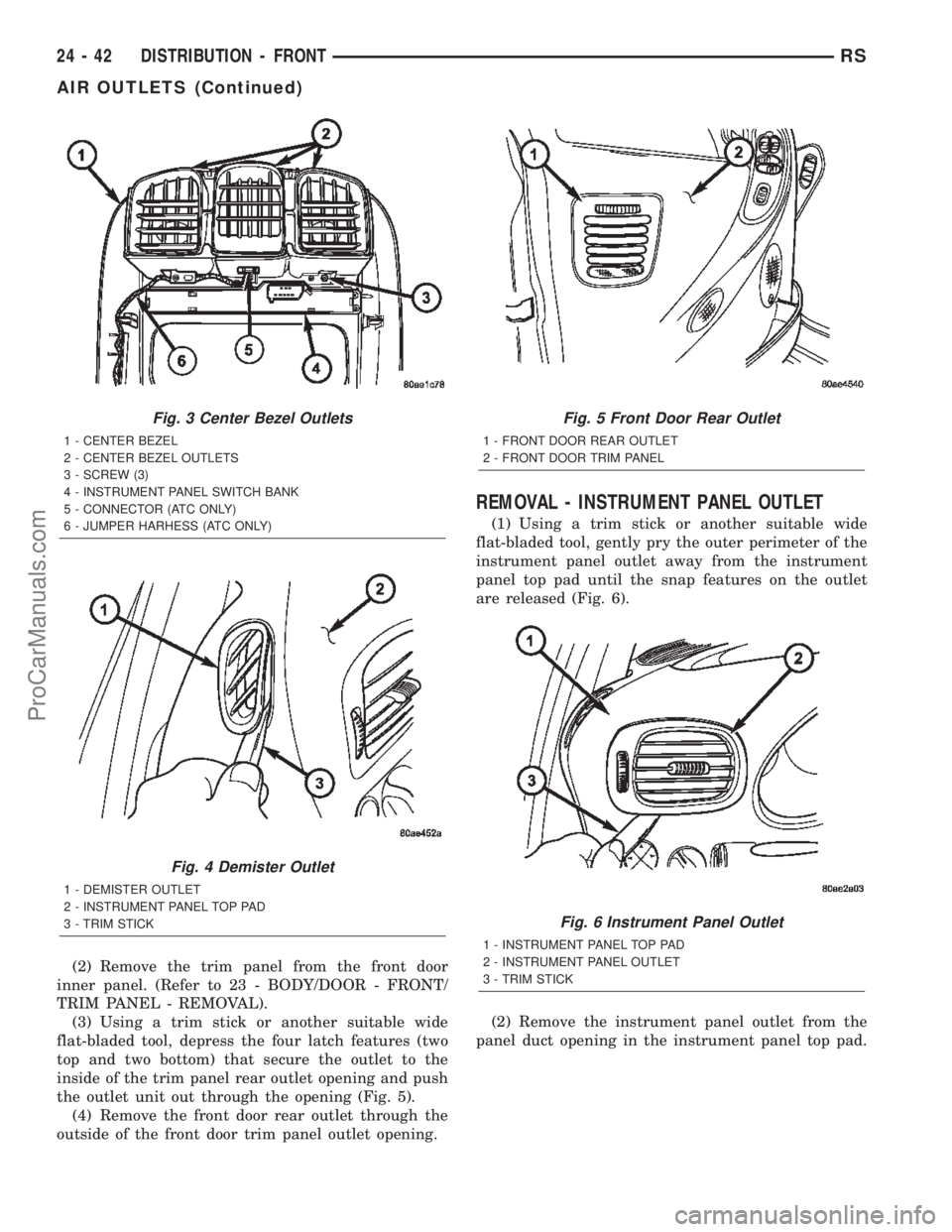
ter outlet housing (Fig. 3).
(5) Remove the three screws that secure the bot-
tom of the outlet housing to the center bezel.
(6) Roll the bottom of the outlet housing upwards
towards the top of the center bezel far enough to dis-
engage the retainer features on the top of the outlet
housing from their receptacles at the top of the cen-
ter bezel.
(7) Remove the center bezel outlets and housing
from the center bezel as a unit.
REMOVAL - DEMISTER OUTLET
(1) Using a trim stick or another suitable wide
flat-bladed tool, gently pry the outer perimeter of the
demister outlet away from the instrument panel top
pad until the snap features on the outlet are released
(Fig. 4).
(2) Remove the demister outlet from the demister
duct opening in the instrument panel top pad.
REMOVAL - FRONT DOOR REAR OUTLET
(1) Disconnect and isolate the battery negative
cable.
RSDISTRIBUTION - FRONT24-41
AIR OUTLETS (Continued)
ProCarManuals.com
Page 2285 of 2399
(2) Remove the trim panel from the front door
inner panel. (Refer to 23 - BODY/DOOR - FRONT/
TRIM PANEL - REMOVAL).
(3) Using a trim stick or another suitable wide
flat-bladed tool, depress the four latch features (two
top and two bottom) that secure the outlet to the
inside of the trim panel rear outlet opening and push
the outlet unit out through the opening (Fig. 5).
(4) Remove the front door rear outlet through the
outside of the front door trim panel outlet opening.
REMOVAL - INSTRUMENT PANEL OUTLET
(1) Using a trim stick or another suitable wide
flat-bladed tool, gently pry the outer perimeter of the
instrument panel outlet away from the instrument
panel top pad until the snap features on the outlet
are released (Fig. 6).
(2) Remove the instrument panel outlet from the
panel duct opening in the instrument panel top pad.
Fig. 3 Center Bezel Outlets
1 - CENTER BEZEL
2 - CENTER BEZEL OUTLETS
3 - SCREW (3)
4 - INSTRUMENT PANEL SWITCH BANK
5 - CONNECTOR (ATC ONLY)
6 - JUMPER HARHESS (ATC ONLY)
Fig. 4 Demister Outlet
1 - DEMISTER OUTLET
2 - INSTRUMENT PANEL TOP PAD
3 - TRIM STICK
Fig. 5 Front Door Rear Outlet
1 - FRONT DOOR REAR OUTLET
2 - FRONT DOOR TRIM PANEL
Fig. 6 Instrument Panel Outlet
1 - INSTRUMENT PANEL TOP PAD
2 - INSTRUMENT PANEL OUTLET
3 - TRIM STICK
24 - 42 DISTRIBUTION - FRONTRS
AIR OUTLETS (Continued)
ProCarManuals.com
Page 2286 of 2399
INSTALLATION
INSTALLATION - CENTER BEZEL OUTLETS
(1) Position the center bezel outlets and housing
onto the center bezel as a unit.
(2) Engage the retainer features on the top of the
outlet housing with their receptacles at the top of the
center bezel, then roll the bottom of the outlet hous-
ing downwards towards the center bezel.
(3) Install and tighten the three screws that secure
the bottom of the outlet housing to the center bezel.
Tighten the screws to 2 N´m (17 in. lbs.).
(4) If the vehicle is equipped with the optional
ATC system, reconnect the ATC remote infrared tem-
perature sensor jumper harness to the sensor connec-
tor receptacle located on the bottom of the center
outlet housing.
(5) Reinstall the center bezel onto the instrument
panel. (Refer to 23 - BODY/INSTRUMENT PANEL/
INSTRUMENT PANEL CENTER BEZEL - INSTAL-
LATION).
(6) Reconnect the battery negative cable.
INSTALLATION - DEMISTER OUTLET
(1) Position the demister outlet over the demister
duct opening in the instrument panel top pad.
(2) Using hand pressure, press the demister outlet
firmly and evenly into the instrument panel top pad
opening until the snap features on the outlet are
fully engaged.
INSTALLATION - FRONT DOOR REAR OUTLET
(1) Position the front door rear outlet through the
outside of the front door trim panel outlet opening.
(2) While keeping the outlet aligned with the door
duct opening behind the trim panel, use hand pres-
sure to press the outlet firmly and evenly through
the outside of the front door trim panel outlet open-
ing until the four latch features (two top and two bot-
tom) that secure the outlet to the inside of the
opening are fully engaged.
(3) Reinstall the trim panel onto the front door
inner panel. (Refer to 23 - BODY/DOOR - FRONT/
TRIM PANEL - INSTALLATION).
(4) Reconnect the battery negative cable.
INSTALLATION - INSTRUMENT PANEL OUTLET
(1) Position the instrument panel outlet into the
panel duct opening in the instrument panel top pad.
(2) Using hand pressure, press the instrument
panel outlet firmly and evenly into the instrument
panel top pad opening until the snap features on the
outlet are fully engaged.
BLOWER MOTOR
DESCRIPTION
The blower motor is a 12-volt, Direct Current (DC)
motor with a squirrel cage-type blower wheel that is
secured to the blower motor shaft (Fig. 7). The
blower motor and wheel are located near the passen-
ger side end of the heater-A/C unit within the two
halves of the intake air housing in the passenger
compartment below the instrument panel. The
blower motor and blower motor wheel are a factory
balanced unit and cannot be adjusted or repaired. If
faulty or damaged, the blower motor and blower
wheel must be replaced as a unit.
OPERATION
The blower motor will operate whenever the igni-
tion switch is in the On position and the heater-A/C
control power is turned on. The blower motor can
only be turned off by turning off the power at the
heater-A/C control. The blower motor receives battery
current whenever the front blower motor relay is
energized. The front blower motor relay output cir-
cuit is protected by a fuse in the Intelligent Power
Module (IPM) located in the engine compartment
near the battery. In the Manual system, the blower
motor speed is controlled by regulating the path to
ground through the blower control switch and the
blower motor resistor. In the ATC system, the blower
motor speed is controlled by an electronic blower
power module, which uses a pulse width modulated
input from the ATC module and feedback from the
blower motor to regulate the blower motor ground
Fig. 7 Blower Motor
1 - BLOWER MOTOR
2 - RUBBER GROMMET
3 - BLOWER MOTOR CONNECTOR
4 - MOUNTING TABS
RSDISTRIBUTION - FRONT24-43
AIR OUTLETS (Continued)
ProCarManuals.com
Page 2287 of 2399
path it provides. The blower motor and wheel are
used to control the velocity of air moving through the
heater-A/C unit housing. The blower motor controls
the velocity of the air flowing through the heater-A/C
housing by spinning the blower wheel within the
housing at the selected speed or, in the ATC system,
at the selected or programmed speed.
DIAGNOSIS AND TESTING - BLOWER MOTOR
BLOWER MOTOR INOPERATIVE
WARNING: ON VEHICLES EQUIPPED WITH AIR-
BAGS, DISABLE THE AIRBAG SYSTEM BEFORE
ATTEMPTING ANY STEERING WHEEL, STEERING
COLUMN, OR INSTRUMENT PANEL COMPONENT
DIAGNOSIS OR SERVICE. DISCONNECT AND ISO-
LATE THE BATTERY NEGATIVE (GROUND) CABLE,
THEN WAIT TWO MINUTES FOR THE AIRBAG SYS-
TEM CAPACITOR TO DISCHARGE BEFORE PER-
FORMING FURTHER DIAGNOSIS OR SERVICE. THIS
IS THE ONLY SURE WAY TO DISABLE THE AIRBAG
SYSTEM. FAILURE TO TAKE THE PROPER PRE-
CAUTIONS COULD RESULT IN ACCIDENTAL AIR-
BAG DEPLOYMENT AND POSSIBLE PERSONAL
INJURY.
(1) Check the fuse (Fuse 10 - 40 ampere) in the
Intelligent Power Module (IPM). If OK, go to Step 2.
If not OK, repair the shorted circuit or component as
required and replace the faulty fuse.
(2) Turn the ignition switch to the On position. Be
certain that the heater-A/C control power is turned
on. Check for battery voltage at the fuse (Fuse 10 -
40 ampere) in the IPM. If OK, go to Step 3. If not
OK, proceed to diagnosis of the front blower motor
relay. (Refer to 24 - HEATING & AIR CONDITION-
ING/CONTROLS - FRONT/BLOWER MOTOR
RELAY - DIAGNOSIS AND TESTING).
(3) Turn the ignition switch to the Off position.
Disconnect and isolate the battery negative cable.
Disconnect the front HVAC wire harness connector
for the front blower motor resistor (Manual Temper-
ature Control) or the front blower power module
(Automatic Temperature Control) from the resistor or
module connector receptacle. Reconnect the battery
negative cable. Turn the ignition switch to the On
position. Be certain that the heater-A/C control
power is turned on. Check for battery voltage at the
fused front blower motor relay output circuit cavity
of the front HVAC wire harness connector for the
front blower motor resistor (MTC) or the front blower
power module (ATC). If OK, go to Step 4. If not OK,
repair the open fused front blower motor relay output
circuit to the IPM as required.
(4) Turn the ignition switch to the Off position.
Disconnect and isolate the battery negative cable.Disconnect the front blower motor pigtail wire con-
nector from the connector receptacle of the front
blower motor resistor (MTC) or the front blower
power module (ATC). Use jumper wires to connect a
battery and ground feeds to the blower motor pigtail
wire connector. The blower motor should operate. If
OK with MTC, proceed to diagnosis of the front
blower motor resistor. (Refer to 24 - HEATING & AIR
CONDITIONING/CONTROLS - FRONT/BLOWER
MOTOR RESISTOR - DIAGNOSIS AND TESTING).
If OK with ATC, use a DRBIII scan tool to diagnose
the front blower power module. Refer to the appropri-
ate diagnostic information. If not OK with MTC or
ATC, replace the faulty front blower motor.
BLOWER MOTOR NOISE OR VIBRATION
Refer to the Blower Motor Noise/Vibration Diagno-
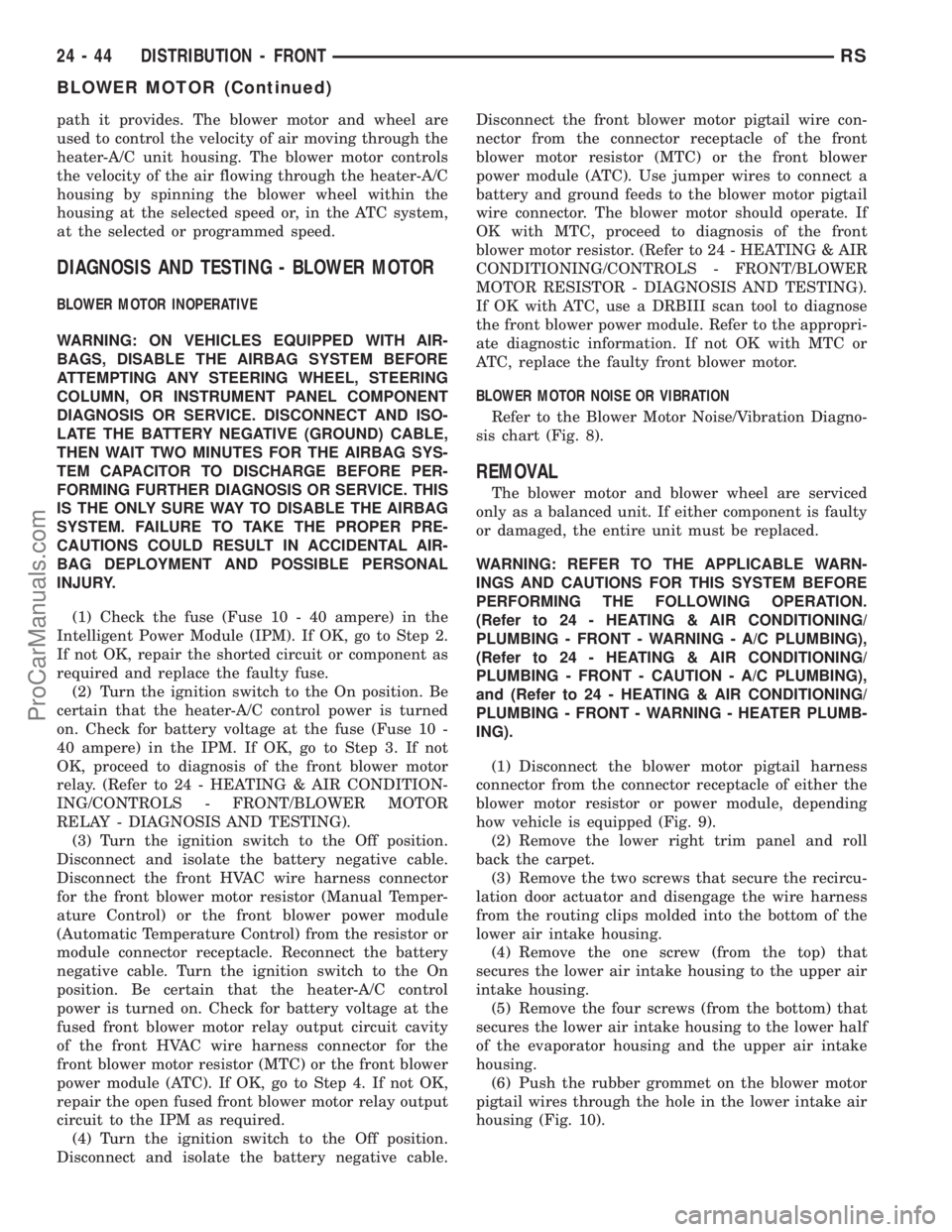
sis chart (Fig. 8).
REMOVAL
The blower motor and blower wheel are serviced
only as a balanced unit. If either component is faulty
or damaged, the entire unit must be replaced.
WARNING: REFER TO THE APPLICABLE WARN-
INGS AND CAUTIONS FOR THIS SYSTEM BEFORE
PERFORMING THE FOLLOWING OPERATION.
(Refer to 24 - HEATING & AIR CONDITIONING/
PLUMBING - FRONT - WARNING - A/C PLUMBING),
(Refer to 24 - HEATING & AIR CONDITIONING/
PLUMBING - FRONT - CAUTION - A/C PLUMBING),
and (Refer to 24 - HEATING & AIR CONDITIONING/
PLUMBING - FRONT - WARNING - HEATER PLUMB-
ING).
(1) Disconnect the blower motor pigtail harness
connector from the connector receptacle of either the
blower motor resistor or power module, depending
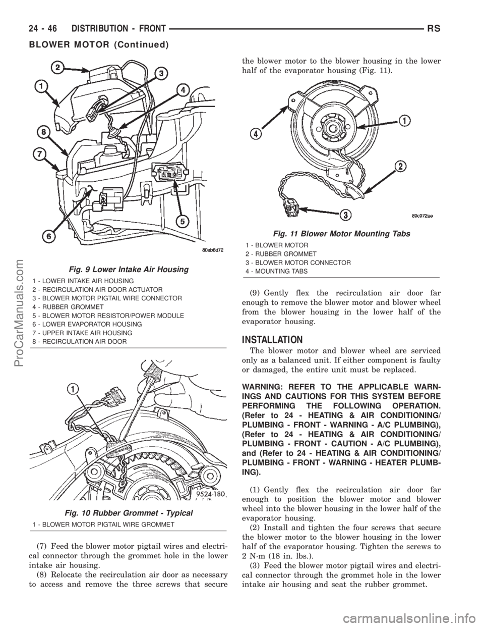
how vehicle is equipped (Fig. 9).
(2) Remove the lower right trim panel and roll
back the carpet.
(3) Remove the two screws that secure the recircu-
lation door actuator and disengage the wire harness
from the routing clips molded into the bottom of the
lower air intake housing.
(4) Remove the one screw (from the top) that
secures the lower air intake housing to the upper air
intake housing.
(5) Remove the four screws (from the bottom) that
secures the lower air intake housing to the lower half
of the evaporator housing and the upper air intake
housing.
(6) Push the rubber grommet on the blower motor
pigtail wires through the hole in the lower intake air
housing (Fig. 10).
24 - 44 DISTRIBUTION - FRONTRS
BLOWER MOTOR (Continued)
ProCarManuals.com
Page 2289 of 2399
(7) Feed the blower motor pigtail wires and electri-
cal connector through the grommet hole in the lower
intake air housing.
(8) Relocate the recirculation air door as necessary
to access and remove the three screws that securethe blower motor to the blower housing in the lower
half of the evaporator housing (Fig. 11).
(9) Gently flex the recirculation air door far
enough to remove the blower motor and blower wheel
from the blower housing in the lower half of the
evaporator housing.
INSTALLATION
The blower motor and blower wheel are serviced
only as a balanced unit. If either component is faulty
or damaged, the entire unit must be replaced.
WARNING: REFER TO THE APPLICABLE WARN-
INGS AND CAUTIONS FOR THIS SYSTEM BEFORE
PERFORMING THE FOLLOWING OPERATION.
(Refer to 24 - HEATING & AIR CONDITIONING/
PLUMBING - FRONT - WARNING - A/C PLUMBING),
(Refer to 24 - HEATING & AIR CONDITIONING/
PLUMBING - FRONT - CAUTION - A/C PLUMBING),
and (Refer to 24 - HEATING & AIR CONDITIONING/
PLUMBING - FRONT - WARNING - HEATER PLUMB-
ING).
(1) Gently flex the recirculation air door far
enough to position the blower motor and blower
wheel into the blower housing in the lower half of the
evaporator housing.
(2) Install and tighten the four screws that secure
the blower motor to the blower housing in the lower
half of the evaporator housing. Tighten the screws to
2 N´m (18 in. lbs.).
(3) Feed the blower motor pigtail wires and electri-
cal connector through the grommet hole in the lower
intake air housing and seat the rubber grommet.
Fig. 9 Lower Intake Air Housing
1 - LOWER INTAKE AIR HOUSING
2 - RECIRCULATION AIR DOOR ACTUATOR
3 - BLOWER MOTOR PIGTAIL WIRE CONNECTOR
4 - RUBBER GROMMET
5 - BLOWER MOTOR RESISTOR/POWER MODULE
6 - LOWER EVAPORATOR HOUSING
7 - UPPER INTAKE AIR HOUSING
8 - RECIRCULATION AIR DOOR
Fig. 10 Rubber Grommet - Typical
1 - BLOWER MOTOR PIGTAIL WIRE GROMMET
Fig. 11 Blower Motor Mounting Tabs
1 - BLOWER MOTOR
2 - RUBBER GROMMET
3 - BLOWER MOTOR CONNECTOR
4 - MOUNTING TABS
24 - 46 DISTRIBUTION - FRONTRS
BLOWER MOTOR (Continued)
ProCarManuals.com