2002 CHRYSLER CARAVAN steering
[x] Cancel search: steeringPage 1448 of 2399
SPECIFICATIONS - TORQUE
DESCRIPTION N´m Ft. Lbs. In. Lbs.
Front Cradle Crossmember to Fram Rail Attaching Bolts (4) 163 120 Ð
Reinforcement Plate to Crossmember Attaching Bolt Size M14 (9) 153 113 Ð
Reinforcement Plate to Crossmember Attaching Bolt Size M12 (1) 106 78 Ð
Reinforcement Plate to Crossmember Attaching Bolt Size M10 (4) 61 45 Ð
Rear Engine Mount to Crossmember Attaching Through Bolt 68 50 Ð
Radiator Support Crossmember Attaching Bolts 51 38 Ð
FRONT CRADLE
CROSSMEMBER
DESCRIPTION
DESCRIPTION - FRONT CRADLE
CROSSMEMBER
This vehicle uses a one piece cast aluminum cradle
for the front cradle crossmember. The cradle cross-
member is used as the attaching points for the lower
control arms, stabilizer bar and steering gear. The
cradle also has the power steering hoses and the
chassis brake tubes attached to it.
WARNING: If a threaded hole in the suspension cra-
dle needs to be repaired, only use the type of
thread insert and installation procedure specified
for this application.
The threaded holes in the front cradle crossmem-
ber that are used for attachment of the lower control
arm rear bushing retainer, power steering hose and
chassis brake tubes can be repaired. The repair is
done by the installation of a Heli-Coiltthread insert
which has been specifically developed for this appli-
cation. Refer to the Mopar Parts Catalog for the spec-
ified Heli-Coiltthread insert to be used for this
application. The procedure for installing the Heli-
Coiltthread insert is detailed in the Service Proce-
dures section in this group of the service manual.
DESCRIPTION - FRONT CRADLE
CROSSMEMBER THREAD REPAIR
WARNING: When performing this procedure use
only the thread inserts which are specified in the
Mopar Parts Catalog for this repair procedure.
These thread inserts have been specifically devel-
oped for this application and use of other types of
thread inserts can result in an inferior long term
repair.The threaded holes in the front cradle crossmem-
ber, if damaged, can repaired by installing a Heli-
Coiltthread insert.
The threaded holes that are repairable using the
thread insert, are the lower control arm rear bushing
retainer mounting bolt holes, routing bracket attach-
ing locations for the power steering hoses, and brake
hose attachment holes.
This repair procedure now allows the threaded
holes in the cradle crossmember to be repaired, elim-
inating the need to replace the cradle crossmember if
damage occurs to one of the threaded holes.
The thread inserts for this application are specified
by part number in the Mopar Parts Catalog.Do not
use a substitute thread insert.
The specific tools and equipment required to install
the thread insert are listed below. Refer to the
instructions included with the thread insert for the
detailed procedure used for the installation of the
thread insert.
NOTE: The thread inserts for this application are for
the repair of M8x1.25 and M10x1.5 threads. Be sure
the correct tools are used for the required thread
insert size.
TOOL REQUIREMENT FOR M8x1.25 Thread
²8.3mm (5/16 in.) Drill Bit
²120É Countersink
²Heli-CoiltTap #4863-8
²Heli-CoiltGage #4624-8
²Heli-CoiltHand Inserting Tool 7751-8
²Needle Nose Pliers ± For Removal Of Thread
Insert Driving Tang
TOOL REQUIREMENT FOR M10x1.5 Thread
²10.5mm (25/64 in.) Drill Bit
²120É Countersink
²Heli-CoiltTap #4863-10
²Heli-CoiltGage #4624-10
²Heli-CoiltHand Inserting Tool 7751-10
²Needle Nose Pliers ± For Removal Of Thread
Insert Driving Tang
RSFRAME & BUMPERS13-9
FRAME (Continued)
ProCarManuals.com
Page 1449 of 2399
REMOVAL
The front cradle crossmember must be installed in
the design location to achieve proper front end sus-
pension alignment. If the cradle crossmember is
removed without applying reference marks on the
frame rails, align the cradle crossmember according
to the dimensions provided in this group.
NOTE: If the caged nuts in the frame rails become
damaged and cannot be reused, a replacement nut
can be obtained through MoparT.
REMOVAL
(1) Disconnect battery negative cable.
(2) Remove steering column lower cover from
instrument panel (Refer to 23 - BODY/INSTRU-
MENT PANEL/STEERING COLUMN OPENING
COVER - REMOVAL).
(3) Remove steering column cover backing plate
(Refer to 23 - BODY/INSTRUMENT PANEL/STEER-
ING COLUMN COVER BACKING PLATE - REMOV-
AL).
(4) Position steering so front wheels are straight
ahead.
CAUTION: Do not rotate steering wheel after disen-
gaging lower coupling from steering gear, damage
to air bag clock spring can result.
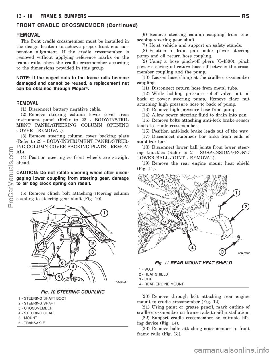
(5) Remove clinch bolt attaching steering column
coupling to steering gear shaft (Fig. 10).(6) Remove steering column coupling from tele-
scoping steering gear shaft.
(7) Hoist vehicle and support on safety stands.
(8) Position a drain pan under power steering
pump and oil return hose coupling.
(9) Using a hose pinch-off pliers (C-4390), pinch
power steering oil return hose off between the cross-
member coupling and the pump.
(10) Loosen hose clamp at the cradle crossmember
coupling.
(11) Disconnect return hose from metal tube.
(12) While holding pressure relief valve nut on
back of power steering pump, Remove flare nut
attaching high pressure hose to back of pump.
(13) Remove high pressure hose from pump.
(14) Allow power steering fluid to drain into pan.
(15) Remove bolts attaching anti-lock brake sensor
leads to cradle crossmember.
(16) Position anti-lock brake leads out of the way.
(17) Disconnect stabilizer bar links from ends of
stabilizer bar.
(18) Disconnect lower ball joints from lower steer-
ing knuckles (Refer to 2 - SUSPENSION/FRONT/
LOWER BALL JOINT - REMOVAL).
(19) Remove the rear engine mount heat shield
(Fig. 11).
(20) Remove through bolt attaching rear engine
mount to cradle crossmember (Fig. 12).
(21) Using paint or grease pencil, mark outline of
cradle crossmember on frame rails to aid installation.
(22) Support cradle crossmember on suitable lift-
ing device (Fig. 14).
(23) Remove bolts attaching crossmember to front
frame rails (Fig. 13).
Fig. 10 STEERING COUPLING
1 - STEERING SHAFT BOOT
2 - STEERING SHAFT
3 - CROSSMEMBER
4 - STEERING GEAR
5 - MOUNT
6 - TRANSAXLE
Fig. 11 REAR MOUNT HEAT SHIELD
1 - BOLT
2 - HEAT SHIELD
3 - CLIP
4 - REAR ENGINE MOUNT
13 - 10 FRAME & BUMPERSRS
FRONT CRADLE CROSSMEMBER (Continued)
ProCarManuals.com
Page 1450 of 2399
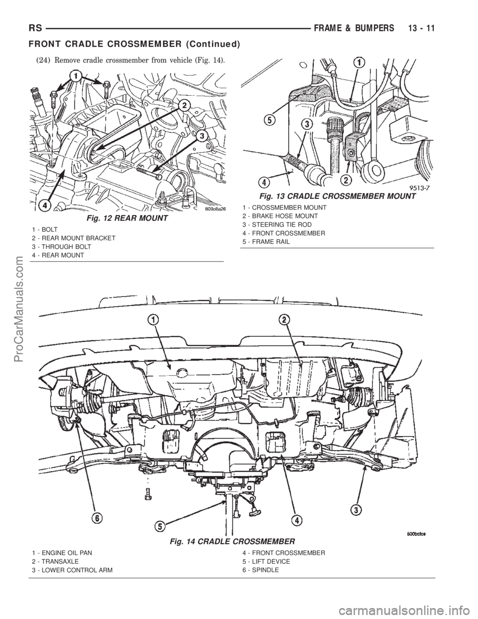
(24)Remove cradle crossmember from vehicle (Fig. 14).
Fig. 12 REAR MOUNT
1 - BOLT
2 - REAR MOUNT BRACKET
3 - THROUGH BOLT
4 - REAR MOUNT
Fig. 13 CRADLE CROSSMEMBER MOUNT
1 - CROSSMEMBER MOUNT
2 - BRAKE HOSE MOUNT
3 - STEERING TIE ROD
4 - FRONT CROSSMEMBER
5 - FRAME RAIL
Fig. 14 CRADLE CROSSMEMBER
1 - ENGINE OIL PAN
2 - TRANSAXLE
3 - LOWER CONTROL ARM4 - FRONT CROSSMEMBER
5 - LIFT DEVICE
6 - SPINDLE
RSFRAME & BUMPERS13-11
FRONT CRADLE CROSSMEMBER (Continued)
ProCarManuals.com
Page 1451 of 2399
INSTALLATION
NOTE: If cradle crossmember requires replacement.
Refer to Group 2, Suspension, to transfer suspen-
sion components and Group 19, Steering, to trans-
fer steering components.
(1) Support crossmember on suitable lifting device
(Fig. 14).
(2) Position crossmember to vehicle.
(3) Loosely install bolts attaching cradle cross-
member to front frame rails.
(4) Align crossmember to previously made marks
on frame rails.
(5) Tighten bolts attaching cradle crossmember to
frame rails.
(6) Install through bolt attaching rear engine
mount to cradle crossmember (Fig. 12) and tighten to
68 N´m (50 ft. lbs.) torque.
(7) Install the rear mount heat shield (Fig. 11).
(8) Connect lower ball joints to steering knuckles
(Refer to 2 - SUSPENSION/FRONT/LOWER BALL
JOINT - INSTALLATION)
(9) Connect stabilizer bar links to ends of stabi-
lizer bar.
(10) Install bolts attaching anti-lock brake sensor
leads to cradle crossmember.
(11) Install high pressure hose to pump.
(12) Connect return hose to metal tube.
(13) Tighten hose clamp at the cradle crossmember
coupling.
(14) Remove pinch-off pliers.
(15) Position steering so front wheels are straight
ahead.
(16) Install steering column coupling to telescoping
steering gear shaft.
(17) Install clinch bolt attaching steering column
coupling to steering gear shaft.
(18) Install steering column cover backing plate
(Refer to 23 - BODY/INSTRUMENT PANEL/STEER-
ING COLUMN COVER BACKING PLATE -
INSTALLATION)
(19) Install steering column lower cover from
instrument panel (Refer to 23 - BODY/INSTRU-MENT PANEL/STEERING COLUMN OPENING
COVER - INSTALLATION).
(20) Connect battery negative cable.
FRONT CROSSMEMBER
MOUNT BUSHINGS
REMOVAL
(1) Using paint or grease pencil, mark outline of
cradle crossmember on frame rails.
(2) Loosen bolts attaching crossmember to frame
rails.
(3) Remove bolt on bushing that requires replace-
ment.
(4) Allow cradle crossmember to drop down enough
to gain clearance for bushing removal.
(5) Remove bushing from vehicle.
INSTALLATION
(1) Apply rubber lubrication or soap to replace-
ment bushing.
(2) Insert lower half of bushing into square hole in
cradle crossmember.
(3) Place upper half of bushing on top of cross-
member aligned to receive square tube protruding
upward from lower bushing half.
(4) Squeeze bushing halves together to ensure they
are properly mated.
(5) Lift cradle crossmember upward to close gap
between the bushing and frame.
(6) Verify that lower bushing is fully seated into
cradle crossmember and upper bushing.
(7) Install bolt attaching bushing and crossmember
to frame rail hand tight.
(8) Align cradle crossmember to reference marks
on frame rails.
(9) Tighten cradle crossmember to frame rails
attaching bolts to 163 N´m (120 ft. lbs.) torque.
13 - 12 FRAME & BUMPERSRS
FRONT CRADLE CROSSMEMBER (Continued)
ProCarManuals.com
Page 1472 of 2399
SYSTEM DIAGNOSIS
OPERATION
The PCM can test many of its own input and out-
put circuits. If the PCM senses a fault in a major
system, the PCM stores a Diagnostic Trouble Code
(DTC) in memory.For DTC information see On-Board Diagnostics
(Refer to 8 - ELECTRICAL/ELECTRONIC CON-
TROL MODULES/POWERTRAIN CONTROL MOD-
ULE - DESCRIPTION) .
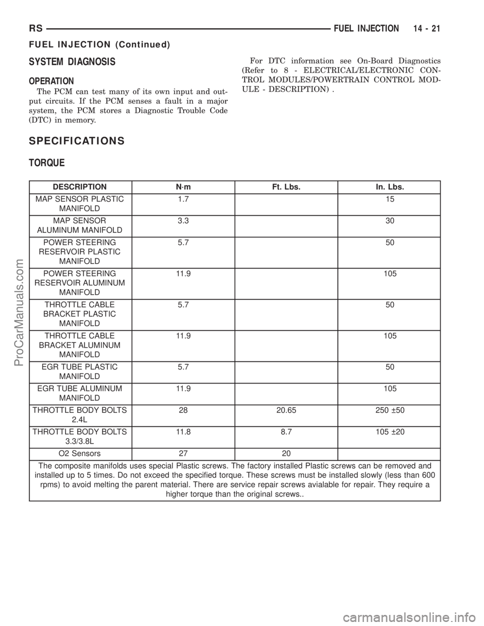
SPECIFICATIONS
TORQUE
DESCRIPTION N´m Ft. Lbs. In. Lbs.
MAP SENSOR PLASTIC
MANIFOLD1.7 15
MAP SENSOR
ALUMINUM MANIFOLD3.3 30
POWER STEERING
RESERVOIR PLASTIC
MANIFOLD5.7 50
POWER STEERING
RESERVOIR ALUMINUM
MANIFOLD11.9 105
THROTTLE CABLE
BRACKET PLASTIC
MANIFOLD5.7 50
THROTTLE CABLE
BRACKET ALUMINUM
MANIFOLD11.9 105
EGR TUBE PLASTIC
MANIFOLD5.7 50
EGR TUBE ALUMINUM
MANIFOLD11.9 105
THROTTLE BODY BOLTS
2.4L28 20.65 250 50
THROTTLE BODY BOLTS
3.3/3.8L11.8 8.7 105 20
O2 Sensors 27 20
The composite manifolds uses special Plastic screws. The factory installed Plastic screws can be removed and
installed up to 5 times. Do not exceed the specified torque. These screws must be installed slowly (less than 600
rpms) to avoid melting the parent material. There are service repair screws avialable for repair. They require a
higher torque than the original screws..
RSFUEL INJECTION14-21
FUEL INJECTION (Continued)
ProCarManuals.com
Page 1494 of 2399
CAUTION: The high-pressure fuel lines cannot con-
tact each other or other components. Do not
attempt to weld high-pressure fuel lines or to repair
lines that are damaged. Only use the recommended
lines when replacement of high-pressure fuel line is
necessary.
FUEL TRANSFER PUMP
DESCRIPTION
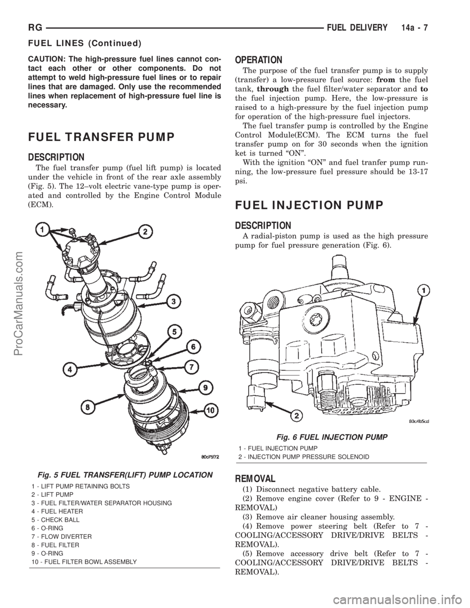
The fuel transfer pump (fuel lift pump) is located
under the vehicle in front of the rear axle assembly
(Fig. 5). The 12±volt electric vane-type pump is oper-
ated and controlled by the Engine Control Module
(ECM).
OPERATION
The purpose of the fuel transfer pump is to supply
(transfer) a low-pressure fuel source:fromthe fuel
tank,throughthe fuel filter/water separator andto
the fuel injection pump. Here, the low-pressure is
raised to a high-pressure by the fuel injection pump
for operation of the high-pressure fuel injectors.
The fuel transfer pump is controlled by the Engine
Control Module(ECM). The ECM turns the fuel
transfer pump on for 30 seconds when the ignition
ket is turned ªONº.
With the ignition ªONº and fuel tranfer pump run-
ning, the low-pressure fuel pressure should be 13-17
psi.
FUEL INJECTION PUMP
DESCRIPTION
A radial-piston pump is used as the high pressure
pump for fuel pressure generation (Fig. 6).
REMOVAL
(1) Disconnect negative battery cable.
(2) Remove engine cover (Refer to 9 - ENGINE -
REMOVAL)
(3) Remove air cleaner housing assembly.
(4) Remove power steering belt (Refer to 7 -
COOLING/ACCESSORY DRIVE/DRIVE BELTS -
REMOVAL).
(5) Remove accessory drive belt (Refer to 7 -
COOLING/ACCESSORY DRIVE/DRIVE BELTS -
REMOVAL).
Fig. 5 FUEL TRANSFER(LIFT) PUMP LOCATION
1 - LIFT PUMP RETAINING BOLTS
2 - LIFT PUMP
3 - FUEL FILTER/WATER SEPARATOR HOUSING
4 - FUEL HEATER
5 - CHECK BALL
6 - O-RING
7 - FLOW DIVERTER
8 - FUEL FILTER
9 - O-RING
10 - FUEL FILTER BOWL ASSEMBLY
Fig. 6 FUEL INJECTION PUMP
1 - FUEL INJECTION PUMP
2 - INJECTION PUMP PRESSURE SOLENOID
RGFUEL DELIVERY14a-7
FUEL LINES (Continued)
ProCarManuals.com
Page 1497 of 2399
(6) Using special tool VM.1055 (Fig. 7), torque
injection pump sprocket retaining nut to 88.3N´m.
(7) Connect fuel pressure solenoid electrical con-
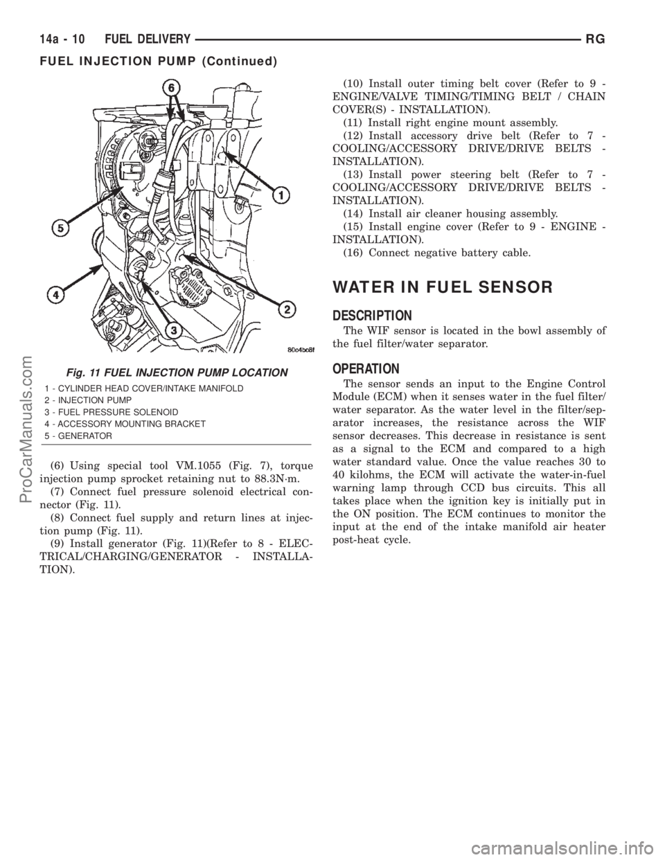
nector (Fig. 11).
(8) Connect fuel supply and return lines at injec-
tion pump (Fig. 11).
(9) Install generator (Fig. 11)(Refer to 8 - ELEC-
TRICAL/CHARGING/GENERATOR - INSTALLA-
TION).(10) Install outer timing belt cover (Refer to 9 -
ENGINE/VALVE TIMING/TIMING BELT / CHAIN
COVER(S) - INSTALLATION).
(11) Install right engine mount assembly.
(12) Install accessory drive belt (Refer to 7 -
COOLING/ACCESSORY DRIVE/DRIVE BELTS -
INSTALLATION).
(13) Install power steering belt (Refer to 7 -
COOLING/ACCESSORY DRIVE/DRIVE BELTS -
INSTALLATION).
(14) Install air cleaner housing assembly.
(15) Install engine cover (Refer to 9 - ENGINE -
INSTALLATION).
(16) Connect negative battery cable.
WATER IN FUEL SENSOR
DESCRIPTION
The WIF sensor is located in the bowl assembly of
the fuel filter/water separator.
OPERATION
The sensor sends an input to the Engine Control
Module (ECM) when it senses water in the fuel filter/
water separator. As the water level in the filter/sep-
arator increases, the resistance across the WIF
sensor decreases. This decrease in resistance is sent
as a signal to the ECM and compared to a high
water standard value. Once the value reaches 30 to
40 kilohms, the ECM will activate the water-in-fuel
warning lamp through CCD bus circuits. This all
takes place when the ignition key is initially put in
the ON position. The ECM continues to monitor the
input at the end of the intake manifold air heater
post-heat cycle.
Fig. 11 FUEL INJECTION PUMP LOCATION
1 - CYLINDER HEAD COVER/INTAKE MANIFOLD
2 - INJECTION PUMP
3 - FUEL PRESSURE SOLENOID
4 - ACCESSORY MOUNTING BRACKET
5 - GENERATOR
14a - 10 FUEL DELIVERYRG
FUEL INJECTION PUMP (Continued)
ProCarManuals.com
Page 1504 of 2399
STEERING
TABLE OF CONTENTS
page page
STEERING
DESCRIPTION - POWER STEERING SYSTEM . . 1
OPERATION - POWER STEERING SYSTEM . . . 1
DIAGNOSIS AND TESTING
DIAGNOSIS AND TESTING - POWER
STEERING SYSTEM FLOW AND
PRESSURE TEST......................1
DIAGNOSIS AND TESTING - STEERING
SYSTEM DIAGNOSIS CHARTS............3SPECIFICATIONS
POWER STEERING FASTENER TORQUE . . . 9
SPECIAL TOOLS
POWER STEERING....................9
COLUMN..............................10
GEAR.................................26
PUMP.................................36
STEERING
DESCRIPTION - POWER STEERING SYSTEM
This vehicle comes with power steering as stan-
dard equipment. The power steering system consists
of these major components:
²POWER STEERING PUMP
²POWER STEERING GEAR
²POWER STEERING FLUID
²POWER STEERING FLUID COOLER
²POWER STEERING FLUID RESERVOIR
²POWER STEERING FLUID SUPPLY HOSE
²POWER STEERING FLUID PRESSURE HOSE
²POWER STEERING FLUID RETURN HOSE
For information on the first two components, refer
to their respective sections within this service man-
ual group. Information on all other components can
be found in POWER STEERING PUMP.
OPERATION - POWER STEERING SYSTEM
Turning of the steering wheel is converted into lin-
ear (side-to-side) travel through the meshing of the
helical pinion teeth with the rack teeth within the
steering gear. The lateral travel pushes and pulls the
tie rods to change the direction of the vehicle's front
wheels.
Power assist steering is provided by a belt driven
rotary type pump. It directs fluid through power
steering fluid hoses to the power steering gear where
it is used to assist the driver's turning effort.
Manual steering control of the vehicle can be main-
tained if power steering assist is lost. However,
under this condition, steering effort is significantly
increased.
DIAGNOSIS AND TESTING
DIAGNOSIS AND TESTING - POWER STEERING
SYSTEM FLOW AND PRESSURE TEST
ALL ENGINES
The following procedure is to be used to test the
operation of the power steering system on this vehi-
cle. This test will provide the flow rate of the power
steering pump along with the maximum relief pres-
sure. This test is to be performed to determine if the
power steering pump or power steering gear is not
functioning properly. The following flow and pressure
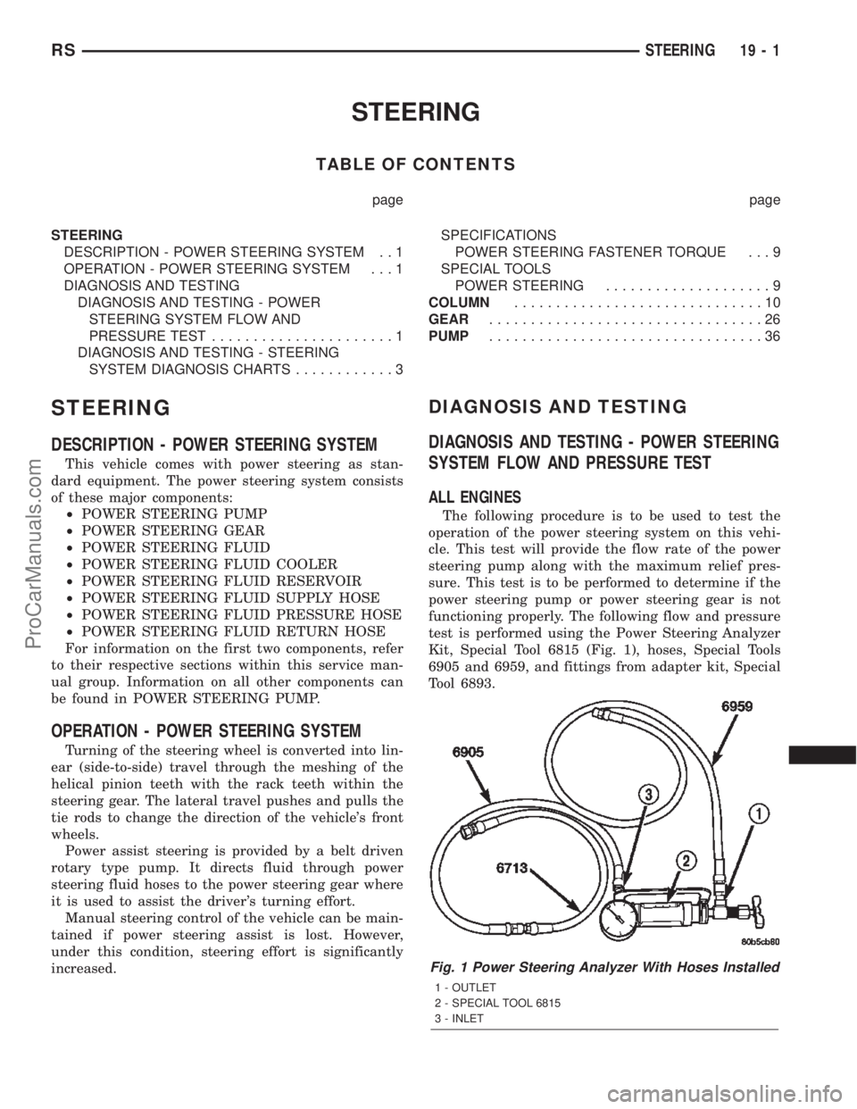
test is performed using the Power Steering Analyzer
Kit, Special Tool 6815 (Fig. 1), hoses, Special Tools
6905 and 6959, and fittings from adapter kit, Special
Tool 6893.
Fig. 1 Power Steering Analyzer With Hoses Installed
1 - OUTLET
2 - SPECIAL TOOL 6815
3 - INLET
RSSTEERING19-1
ProCarManuals.com