2002 CHRYSLER CARAVAN ad blue
[x] Cancel search: ad bluePage 1112 of 2399
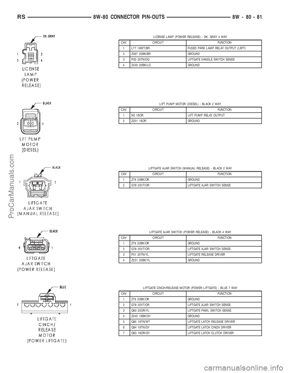
LICENSE LAMP (POWER RELEASE) - DK. GRAY 4 WAY
CAV CIRCUIT FUNCTION
1 L77 18WT/BR FUSED PARK LAMP RELAY OUTPUT (LEFT)
2 Z367 20BK/BR GROUND
3 P30 20TN/DG LIFTGATE HANDLE SWITCH SENSE
4 Z430 20BK/LG GROUND
LIFT PUMP MOTOR (DIESEL) - BLACK 2 WAY
CAV CIRCUIT FUNCTION
1 N2 18OR LIFT PUMP RELAY OUTPUT
2 Z201 18OR GROUND
LIFTGATE AJAR SWITCH (MANUAL RELEASE) - BLACK 2 WAY
CAV CIRCUIT FUNCTION
1 Z78 20BK/OR GROUND
2 G78 20VT/OR LIFTGATE AJAR SWITCH SENSE
LIFTGATE AJAR SWITCH (POWER RELEASE) - BLACK 4 WAY
CAV CIRCUIT FUNCTION
1 Z78 20BK/OR GROUND
2 G78 20VT/OR LIFTGATE AJAR SWITCH SENSE
3 P31 20TN/YL LIFTGATE RELEASE DRIVER
4 Z231 20BK/YL GROUND
LIFTGATE CINCH/RELEASE MOTOR (POWER LIFTGATE) - BLUE 7 WAY
CAV CIRCUIT FUNCTION
1 Z78 20BK/OR GROUND
2 G78 20VT/OR LIFTGATE AJAR SWITCH SENSE
3 Q60 20OR/YL LIFTGATE PAWL SWITCH SENSE
4 Z245 18BK/GY GROUND
5 Q85 18TN/WT LIFTGATE LATCH RELEASE DRIVER
6 Q84 18TN/GY LIFTGATE LATCH CINCH DRIVER
7 Q83 18OR/GY LIFTGATE LATCH CLUTCH DRIVER
RS8W-80 CONNECTOR PIN-OUTS8W-80-81
ProCarManuals.com
Page 1117 of 2399

OUTPUT SPEED SENSOR (EATX) - GRAY 2 WAY
CAV CIRCUIT FUNCTION
1 T13 18DG/VT SPEED SENSOR GROUND
2 T14 18DG/BR OUTPUT SPEED SENSOR SIGNAL
OVERHEAD CONSOLE (EXCEPT BASE) - BLACK 12 WAY
CAV CIRCUIT FUNCTION
1 G23 20VT/DB SLIDING DOORS OVERHEAD SWITCH MUX
2 G25 20VT/TN LIFTGATE SWITCH MUX
3 D25 20WT/VT PCI BUS
4 Z113 20BK/DB GROUND
5 A114 20GY/RD FUSED B(+) (I.O.D.)
6 F503 20WT/PK FUSED IGNITION SWITCH OUTPUT (RUN)
7 Z13 20BK/WT GROUND
8 E15 20OR/DB ASH/RECEIVER LAMP FEED
9- -
10 - -
11 L24 20BK/GY (EXCEPT
BUILT-UP-EXPORT) (PREMIUM/
LUXURY)AUTOMATIC HEADLAMP SWITCH SENSOR
12 L1 20BK/WT (PREMIUM/LUXURY) BACK-UP LAMP FEED
RADIATOR FAN RELAY NO. 1 (DIESEL) - BLUE 9 WAY
CAV CIRCUIT FUNCTION
1- -
2 N201 12DB/LG RADIATOR FAN RELAY NO. 1 OUTPUT
3- -
4 K342 16BR/WT ECM/PCM RELAY OUTPUT
5- -
6 N210 18DB/DG LOW SPEED RADIATOR FAN RELAY CONTROL
7- -
8 A201 12RD/LG FUSED B(+)
9- -
OXYGEN SENSOR 1/1 UPSTREAM (GAS) - BLACK 4 WAY
CAV CIRCUIT FUNCTION
1 K99 18BR/LG OXYGEN SENSOR 1/1 HEATER CONTROL
2 K342 16BR/WT AUTOMATIC SHUT DOWN RELAY OUTPUT
3 K902 18BR/DG OXYGEN SENSOR 1/1 GROUND
4 K41 18DB/LB OXYGEN SENSOR 1/1 SIGNAL
8W - 80 - 86 8W-80 CONNECTOR PIN-OUTSRS
ProCarManuals.com
Page 1119 of 2399
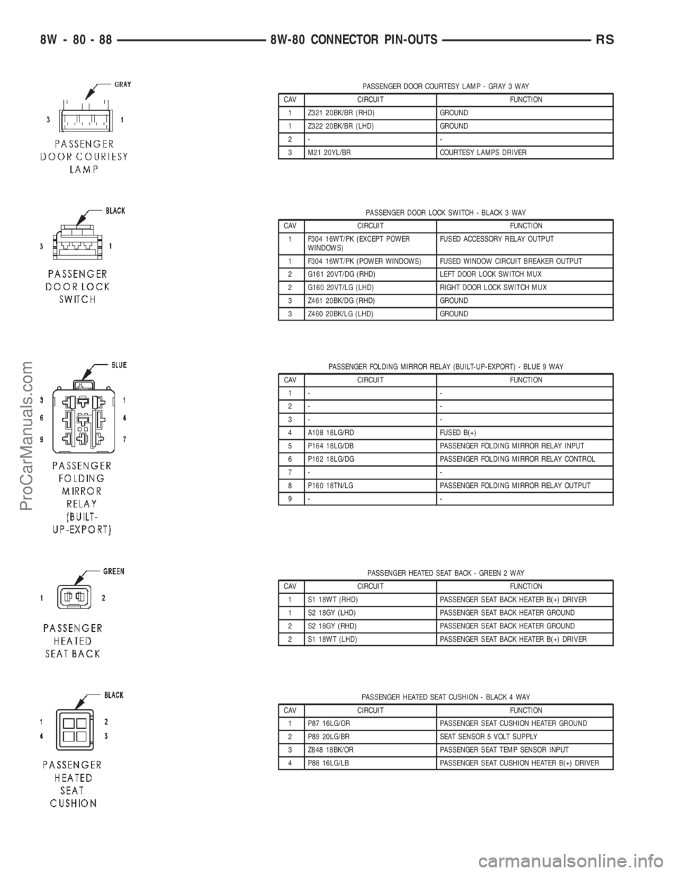
PASSENGER DOOR COURTESY LAMP - GRAY 3 WAY
CAV CIRCUIT FUNCTION
1 Z321 20BK/BR (RHD) GROUND
1 Z322 20BK/BR (LHD) GROUND
2- -
3 M21 20YL/BR COURTESY LAMPS DRIVER
PASSENGER DOOR LOCK SWITCH - BLACK 3 WAY
CAV CIRCUIT FUNCTION
1 F304 16WT/PK (EXCEPT POWER
WINDOWS)FUSED ACCESSORY RELAY OUTPUT
1 F304 16WT/PK (POWER WINDOWS) FUSED WINDOW CIRCUIT BREAKER OUTPUT
2 G161 20VT/DG (RHD) LEFT DOOR LOCK SWITCH MUX
2 G160 20VT/LG (LHD) RIGHT DOOR LOCK SWITCH MUX
3 Z461 20BK/DG (RHD) GROUND
3 Z460 20BK/LG (LHD) GROUND
PASSENGER FOLDING MIRROR RELAY (BUILT-UP-EXPORT) - BLUE 9 WAY
CAV CIRCUIT FUNCTION
1- -
2- -
3- -
4 A108 18LG/RD FUSED B(+)
5 P164 18LG/DB PASSENGER FOLDING MIRROR RELAY INPUT
6 P162 18LG/DG PASSENGER FOLDING MIRROR RELAY CONTROL
7- -
8 P160 18TN/LG PASSENGER FOLDING MIRROR RELAY OUTPUT
9- -
PASSENGER HEATED SEAT BACK - GREEN 2 WAY
CAV CIRCUIT FUNCTION
1 S1 18WT (RHD) PASSENGER SEAT BACK HEATER B(+) DRIVER
1 S2 18GY (LHD) PASSENGER SEAT BACK HEATER GROUND
2 S2 18GY (RHD) PASSENGER SEAT BACK HEATER GROUND
2 S1 18WT (LHD) PASSENGER SEAT BACK HEATER B(+) DRIVER
PASSENGER HEATED SEAT CUSHION - BLACK 4 WAY
CAV CIRCUIT FUNCTION
1 P87 16LG/OR PASSENGER SEAT CUSHION HEATER GROUND
2 P89 20LG/BR SEAT SENSOR 5 VOLT SUPPLY
3 Z848 18BK/OR PASSENGER SEAT TEMP SENSOR INPUT
4 P88 16LG/LB PASSENGER SEAT CUSHION HEATER B(+) DRIVER
8W - 80 - 88 8W-80 CONNECTOR PIN-OUTSRS
ProCarManuals.com
Page 1128 of 2399

RADIATOR FAN RELAY NO. 1 (DIESEL) - BLUE 9 WAY
CAV CIRCUIT FUNCTION
1- -
2 N201 12DB/LG RADIATOR FAN RELAY NO. 1 OUTPUT
3- -
4 K342 16BR/WT ECM/PCM RELAY OUTPUT
5- -
6 N210 18DB/DG LOW SPEED RADIATOR FAN RELAY CONTROL
7- -
8 A201 12RD/LG FUSED B(+)
9- -
RADIATOR FAN RELAY NO. 2 (DIESEL) - BLUE 9 WAY
CAV CIRCUIT FUNCTION
1- -
2 N112 12DB/OR RADIATOR FAN RELAY NO. 2 AND NO. 3 COMMON
OUTPUT
3- -
4 K342 16BR/WT ECM/PCM RELAY OUTPUT
5- -
6 N122 18DB/YL HIGH SPEED RADIATOR FAN DUAL RELAY CONTROL
7- -
8 A112 12OR/RD FUSED B(+)
9- -
RADIATOR FAN RELAY NO. 3 (DIESEL) - BLUE 9 WAY
CAV CIRCUIT FUNCTION
1- -
2 Z823 12BK GROUND
3- -
4 K342 16BR/WT ECM/PCM RELAY OUTPUT
5 N112 12DB/OR RADIATOR FAN RELAY NO. 2 AND NO. 3 COMMON
OUTPUT
6 N122 18DB/YL HIGH SPEED RADIATOR FAN DUAL RELAY CONTROL
7- -
8 N202 12DB/OR RADIATOR FAN NO. 1 CONTROL
9- -
RS8W-80 CONNECTOR PIN-OUTS8W-80-97
ProCarManuals.com
Page 1210 of 2399
(3) Remove torque converter or clutch housing
cover and inspect rear of block for evidence of oil.
Use a black light to check for the oil leak. If a leak is
present in this area, remove transmission for further
inspection.
(a) Circular spray pattern generally indicates
seal leakage or crankshaft damage.
(b) Where leakage tends to run straight down,
possible causes are a porous block, oil gallery cup
plug, bedplate to cylinder block mating surfaces
and seal bore. See proper repair procedures for
these items.
(4) If no leaks are detected, pressurize the crank-
case as previously described.
CAUTION: Do not exceed 20.6 kPa (3 psi).
(5) If the leak is not detected, very slowly turn the
crankshaft and watch for leakage. If a leak is
detected between the crankshaft and seal while
slowly turning the crankshaft, it is possible the
crankshaft seal surface is damaged. The seal area on
the crankshaft could have minor nicks or scratches
that can be polished out with emery cloth.
CAUTION: Use extreme caution when crankshaft
polishing is necessary to remove minor nicks and
scratches. The crankshaft seal flange is especially
machined to complement the function of the rear oil
seal.
(6) For bubbles that remain steady with shaft
rotation, no further inspection can be done until dis-
assembled.
(7) After the oil leak root cause and appropriate
corrective action have been identified, replace compo-
nent(s) as necessary.
DIAGNOSIS AND TESTING - CYLINDER
COMPRESSION PRESSURE TEST
The results of a cylinder compression pressure test
can be utilized to diagnose several engine malfunc-
tions.
Ensure the battery is completely charged and the
engine starter motor is in good operating condition.
Otherwise the indicated compression pressures may
not be valid for diagnosis purposes.
(1) Check engine oil level and add oil if necessary.
(2) Drive the vehicle until engine reaches normal
operating temperature. Select a route free from traf-
fic and other forms of congestion, observe all traffic
laws, and accelerate through the gears several times
briskly.
(3) Remove all spark plugs from engine. As spark
plugs are being removed, check electrodes for abnor-
mal firing indicators fouled, hot, oily, etc. Record cyl-
inder number of spark plug for future reference.(4) Remove the Auto Shutdown (ASD) relay from
the PDC.
(5) Be sure throttle blade is fully open during the
compression check.
(6) Insert compression gauge adaptor Special Tool
8116 or the equivalent, into the #1 spark plug hole in
cylinder head. Connect the 0±500 psi (Blue) pressure
transducer (Special Tool CH7059) with cable adap-
tors to the DRBIIIt. For Special Tool identification,
(Refer to 9 - ENGINE - SPECIAL TOOLS).
(7) Crank engine until maximum pressure is
reached on gauge. Record this pressure as #1 cylin-
der pressure.
(8) Repeat the previous step for all remaining cyl-
inders.
(9) Compression should not be less than 689 kPa
(100 psi) and not vary more than 25 percent from cyl-
inder to cylinder.
(10) If one or more cylinders have abnormally low
compression pressures, repeat the compression test.
(11) If the same cylinder or cylinders repeat an
abnormally low reading on the second compression
test, it could indicate the existence of a problem in
the cylinder in question.The recommended com-
pression pressures are to be used only as a
guide to diagnosing engine problems. An engine
should not be disassembled to determine the
cause of low compression unless some malfunc-
tion is present.
DIAGNOSIS AND TESTING - CYLINDER
COMBUSTION PRESSURE LEAKAGE TEST
The combustion pressure leakage test provides an
accurate means for determining engine condition.
Combustion pressure leakage testing will detect:
²Exhaust and intake valve leaks (improper seat-
ing).
²Leaks between adjacent cylinders or into water
jacket.
²Any causes for combustion/compression pressure
loss.
WARNING: DO NOT REMOVE THE PRESSURE CAP
WITH THE SYSTEM HOT AND UNDER PRESSURE
BECAUSE SERIOUS BURNS FROM COOLANT CAN
OCCUR.
Check the coolant level and fill as required. DO
NOT install the pressure cap.
Start and operate the engine until it attains nor-
mal operating temperature, then turn the engine
OFF.
Clean spark plug recesses with compressed air.
Remove the spark plugs.
Remove the oil filler cap.
Remove the air cleaner.
RSENGINE 2.4L9-9
ENGINE 2.4L (Continued)
ProCarManuals.com
Page 1284 of 2399
(3) Remove torque converter or clutch housing
cover and inspect rear of block for evidence of oil.
Use a black light to check for the oil leak. If a leak is
present in this area, remove transmission for further
inspection.
(a) Circular spray pattern generally indicates
seal leakage or crankshaft damage.
(b) Where leakage tends to run straight down,
possible causes are a porous block, oil gallery cup
plug, bedplate to cylinder block mating surfaces
and seal bore. See proper repair procedures for
these items.
(4) If no leaks are detected, pressurize the crank-
case as previously described.
CAUTION: Do not exceed 20.6 kPa (3 psi).
(5) If the leak is not detected, very slowly turn the
crankshaft and watch for leakage. If a leak is
detected between the crankshaft and seal while
slowly turning the crankshaft, it is possible the
crankshaft seal surface is damaged. The seal area on
the crankshaft could have minor nicks or scratches
that can be polished out with emery cloth.
CAUTION: Use extreme caution when crankshaft
polishing is necessary to remove minor nicks and
scratches. The crankshaft seal flange is especially
machined to complement the function of the rear oil
seal.
(6) For bubbles that remain steady with shaft
rotation, no further inspection can be done until dis-
assembled.
(7) After the oil leak root cause and appropriate
corrective action have been identified, replace compo-
nent(s) as necessary.
DIAGNOSIS AND TESTING - CYLINDER
COMPRESSION PRESSURE TEST
The results of a cylinder compression pressure test
can be utilized to diagnose several engine malfunc-
tions.
Ensure the battery is completely charged and the
engine starter motor is in good operating condition.
Otherwise the indicated compression pressures may
not be valid for diagnosis purposes.
(1) Check engine oil level and add oil if necessary.
(2) Drive the vehicle until engine reaches normal
operating temperature. Select a route free from traf-
fic and other forms of congestion, observe all traffic
laws, and accelerate through the gears several times
briskly.
(3) Remove all spark plugs from engine. As spark
plugs are being removed, check electrodes for abnor-
mal firing indicators fouled, hot, oily, etc. Record cyl-
inder number of spark plug for future reference.(4) Remove the Auto Shutdown (ASD) relay from
the PDC.
(5) Be sure throttle blade is fully open during the
compression check.
(6) Insert compression gauge adaptor Special Tool
8116 or the equivalent, into the #1 spark plug hole in
cylinder head. Connect the 0±500 psi (Blue) pressure
transducer (Special Tool CH7059) with cable adap-
tors to the DRBIIIt. For Special Tool identification,
(Refer to 9 - ENGINE - SPECIAL TOOLS).
(7) Crank engine until maximum pressure is
reached on gauge. Record this pressure as #1 cylin-
der pressure.
(8) Repeat the previous step for all remaining cyl-
inders.
(9) Compression should not be less than 689 kPa
(100 psi) and not vary more than 25 percent from cyl-
inder to cylinder.
(10) If one or more cylinders have abnormally low
compression pressures, repeat the compression test.
(11) If the same cylinder or cylinders repeat an
abnormally low reading on the second compression
test, it could indicate the existence of a problem in
the cylinder in question.The recommended com-
pression pressures are to be used only as a
guide to diagnosing engine problems. An engine
should not be disassembled to determine the
cause of low compression unless some malfunc-
tion is present.
DIAGNOSIS AND TESTING - CYLINDER
COMBUSTION PRESSURE LEAKAGE TEST
The combustion pressure leakage test provides an
accurate means for determining engine condition.
Combustion pressure leakage testing will detect:
²Exhaust and intake valve leaks (improper seat-
ing).
²Leaks between adjacent cylinders or into water
jacket.
²Any causes for combustion/compression pressure
loss.
WARNING: DO NOT REMOVE THE PRESSURE CAP
WITH THE SYSTEM HOT AND UNDER PRESSURE
BECAUSE SERIOUS BURNS FROM COOLANT CAN
OCCUR.
Check the coolant level and fill as required. DO
NOT install the pressure cap.
Start and operate the engine until it attains nor-
mal operating temperature, then turn the engine
OFF.
Clean spark plug recesses with compressed air.
Remove the spark plugs.
Remove the oil filler cap.
Remove the air cleaner.
RSENGINE 3.3/3.8L9-83
ENGINE 3.3/3.8L (Continued)
ProCarManuals.com
Page 1307 of 2399
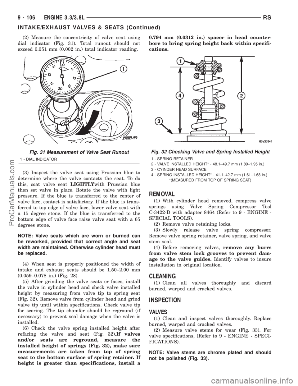
(2) Measure the concentricity of valve seat using
dial indicator (Fig. 31). Total runout should not
exceed 0.051 mm (0.002 in.) total indicator reading.
(3) Inspect the valve seat using Prussian blue to
determine where the valve contacts the seat. To do
this, coat valve seatLIGHTLYwith Prussian blue
then set valve in place. Rotate the valve with light
pressure. If the blue is transferred to the center of
valve face, contact is satisfactory. If the blue is trans-
ferred to top edge of valve face, lower valve seat with
a 15 degree stone. If the blue is transferred to the
bottom edge of valve face raise valve seat with a 65
degrees stone.
NOTE: Valve seats which are worn or burned can
be reworked, provided that correct angle and seat
width are maintained. Otherwise cylinder head must
be replaced.
(4) When seat is properly positioned the width of
intake and exhaust seats should be 1.50±2.00 mm
(0.059±0.078 in.) (Fig. 28).
(5) After grinding the valve seats or faces, install
the valve in cylinder head and check valve installed
height by measuring from valve tip to spring seat
(Fig. 32). Remove valve from cylinder head and grind
valve tip until within specifications. Check valve tip
for scoring. The tip chamfer should be reground (if
necessary) to prevent seal damage when the valve is
installed.
(6) Check the valve spring installed height after
refacing the valve and seat (Fig. 32).If valves
and/or seats are reground, measure the
installed height of springs (Fig. 32), make sure
measurements are taken from top of spring
seat to the bottom surface of spring retainer. If
height is greater than specifications, install a0.794 mm (0.0312 in.) spacer in head counter-
bore to bring spring height back within specifi-
cations.
REMOVAL
(1) With cylinder head removed, compress valve
springs using Valve Spring Compressor Tool
C-3422-D with adapter 8464 (Refer to 9 - ENGINE -
SPECIAL TOOLS).
(2) Remove valve retaining locks.
(3) Slowly release valve spring compressor.
Remove valve spring retainer, valve spring, and valve
stem seal.
(4) Before removing valves,remove any burrs
from valve stem lock grooves to prevent dam-
age to the valve guides.Identify valves to insure
installation in original location.
CLEANING
(1) Clean all valves thoroughly and discard
burned, warped and cracked valves.
INSPECTION
VALVES
(1) Clean and inspect valves thoroughly. Replace
burned, warped and cracked valves.
(2) Measure valve stems for wear (Fig. 33). For
valve specifications, (Refer to 9 - ENGINE - SPECI-
FICATIONS).
NOTE: Valve stems are chrome plated and should
not be polished (Fig. 33).
Fig. 31 Measurement of Valve Seat Runout
1 - DIAL INDICATOR
Fig. 32 Checking Valve and Spring Installed Height
1 - SPRING RETAINER
2 - VALVE INSTALLED HEIGHT* - 48.1±49.7 mm (1.89±1.95 in.)
3 - CYINDER HEAD SURFACE
4 - SPRING INSTALLED HEIGHT* - 41.1±42.7 mm (1.61±1.68 in.)
*(MEASURED FROM TOP OF SPRING SEAT)
9 - 106 ENGINE 3.3/3.8LRS
INTAKE/EXHAUST VALVES & SEATS (Continued)
ProCarManuals.com
Page 2020 of 2399
INSTALLATION
NOTE: For power sliding door procedures refer to
POWER SLIDING DOOR SYSTEM in the ELECTRI-
CAL section.
(1) Match the replacement cable up against the old
cable to verify the correct part.
(2) Position the outside handle cable on the side
door.
(3) Connect the outside handle cable on the handle
assembly. Hook the swedged cable end on the handle
link and gently push the cable sleeve retainer in the
handle bracket.
NOTE: The outside handle cable is marked with red
tape. It must be attached to the latch at the lowest
point. This is marked with a ªRº on the latch.
(4) Connect the outside handle cable on the latch
assembly. Hook the swedged cable end on the latch
link and gently push the cable sleeve retainer in the
latch bracket.
(5) Trace the outside handle cable along its routing
path and install on its retaining clips and position
foam insulators. Use previously made schematic as a
guide or remove the opposite side door trim panel
and use that door as a guide.
CAUTION: Be certain replacement cable is routed
and retained correctly and foam insulators are
properly positioned.
(6) Place the watershield into position and press
securely to adhesive making sure to properly route
wiring and linkages.
(7) Install the appropriate side door trim panel on
the vehicle. (Refer to 23 - BODY/DOORS - SLIDING/
TRIM PANEL - INSTALLATION)
(8) Install stop bumper (Refer to 23 - BODY/
DOORS - SLIDING/STOP BUMPER - INSTALLA-
TION).
(9) Connect the negative battery cable.
INSIDE HANDLE CABLE
REMOVAL
NOTE: For power sliding door procedures refer to
POWER SLIDING DOOR SYSTEM in the ELECTRI-
CAL section.
(1) Disconnect and isolate the negative battery
cable.(2) Remove the appropriate side door trim panel
from the vehicle. (Refer to 23 - BODY/DOORS -
SLIDING/TRIM PANEL - REMOVAL)
(3) Peel watershield away from adhesive around
perimeter of inner door panel.
(4) Remove the inside handle assembly from the
side door. (Refer to 23 - BODY/DOORS - SLIDING/
INSIDE LATCH HANDLE - REMOVAL)
(5) Disconnect the inside handle cable from the
handle assembly. Gently pry cable sleeve retainer out
of the handle bracket and then unhook swedged
cable end from the handle link.
(6) Open the side door and remove the latch
assembly. Refer to the Power Side Doors section for
the procedure.
CAUTION: Make note of cable routing and foam
insulator placement. This will prove helpful when
reinstalling replacement cable. Be certain replace-
ment cable is routed and retained correctly.
(7) Trace the inside handle cable along its routing
path and disconnect from its retaining clips.
(8) Disconnect the inside handle cable from the
latch assembly. Gently pry cable sleeve retainer out
of the latch mounting bracket and then unhook
swedged cable end from the latch link.
(9) Remove the inside handle cable from the side
door.
INSTALLATION
NOTE: For power sliding door procedures refer to
POWER SLIDING DOOR SYSTEM in the ELECTRI-
CAL section.
(1) Match the replacement cable up against the old
cable to verify the correct part.
(2) Position the inside handle cable on the side
door.
(3) Connect the inside handle cable on the handle
assembly. Hook the swedged cable end on the handle
link and gently push the cable sleeve retainer in the
handle bracket.
(4) Install the inside handle assembly on the side
door. (Refer to 23 - BODY/DOORS - SLIDING/IN-
SIDE LATCH HANDLE - INSTALLATION)
NOTE: The inside handle cable is marked with blue
tape and must be attached to the latch at the center
(just above the lower cable). This position is
marked with a ªBº on the latch.
(5) Connect the inside handle cable on the latch
assembly. Hook the swedged cable end on the latch
link and gently push the cable sleeve retainer in the
latch bracket.
RSDOORS - SLIDING23-37
OUTSIDE HANDLE CABLE (Continued)
ProCarManuals.com