2002 CHRYSLER CARAVAN CD changer
[x] Cancel search: CD changerPage 924 of 2399

8W-47 AUDIO SYSTEM
Component Page
Accessory Relay................... 8W-47-2, 5
Antenna........................... 8W-47-5
Body Control Module............. 8W-47-2, 5, 7
CD Changer....................... 8W-47-11
Clockspring......................... 8W-47-7
Diagnostic Junction Port............. 8W-47-2, 5
Front Cigar Lighter................ 8W-47-2, 5
Front Control Module............. 8W-47-2, 5, 6
Fuse 5........................... 8W-47-2, 5
Fuse 14.......................... 8W-47-2, 6
G202....................... 8W-47-2, 5, 9, 10
Integrated Power Module.......... 8W-47-2, 5, 6
Left Door Speaker................ 8W-47-3, 8, 9Component Page
Left Instrument Panel Speaker........ 8W-47-3, 8
Left Rear Pillar Speaker.............. 8W-47-10
Left Rear Speaker............... 8W-47-4, 6, 10
Left Remote Radio Switch.............. 8W-47-7
Name Brand Speaker Relay............ 8W-47-6
Radio.............. 8W-47-2, 3, 4, 5, 6, 9, 10, 11
Radio Choke........................ 8W-47-6
Right Door Speaker............... 8W-47-3, 8, 9
Right Instrument Panel Speaker...... 8W-47-3, 8
Right Rear Pillar Speaker............. 8W-47-10
Right Rear Speaker.............. 8W-47-4, 6, 10
Right Remote Radio Switch............ 8W-47-7
RS8W-47 AUDIO SYSTEM8W-47-1
ProCarManuals.com
Page 1033 of 2399
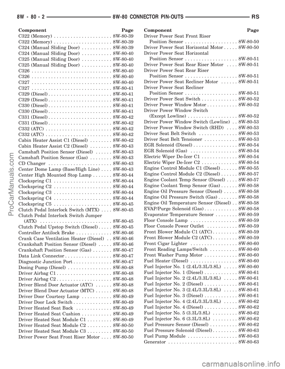
Component Page
C322 (Memory)..................... 8W-80-39
C322 (Memory)..................... 8W-80-39
C324 (Manual Sliding Door)........... 8W-80-39
C324 (Manual Sliding Door)........... 8W-80-40
C325 (Manual Sliding Door)........... 8W-80-40
C325 (Manual Sliding Door)........... 8W-80-40
C326............................. 8W-80-40
C326............................. 8W-80-40
C327............................. 8W-80-40
C327............................. 8W-80-41
C329 (Diesel)....................... 8W-80-41
C329 (Diesel)....................... 8W-80-41
C330 (Diesel)....................... 8W-80-41
C330 (Diesel)....................... 8W-80-41
C331 (Diesel)....................... 8W-80-42
C331 (Diesel)....................... 8W-80-42
C332 (ATC)........................ 8W-80-42
C332 (ATC)........................ 8W-80-42
Cabin Heater Assist C1 (Diesel)........ 8W-80-42
Cabin Heater Assist C2 (Diesel)........ 8W-80-43
Camshaft Position Sensor (Diesel)...... 8W-80-43
Camshaft Position Sensor (Gas)........ 8W-80-43
CD Changer....................... 8W-80-43
Center Dome Lamp (Base/High Line).... 8W-80-43
Center High Mounted Stop Lamp....... 8W-80-44
Clockspring C1..................... 8W-80-44
Clockspring C2..................... 8W-80-44
Clockspring C3..................... 8W-80-44
Clockspring C4..................... 8W-80-44
Clockspring C5..................... 8W-80-45
Clutch Pedal Interlock Switch (MTX).... 8W-80-45
Clutch Pedal Interlock Switch Jumper
(ATX) .......................... 8W-80-45
Clutch Pedal Upstop Switch (Diesel)..... 8W-80-45
Controller Antilock Brake............. 8W-80-46
Crank Case Ventilation Heater (Diesel) . . 8W-80-46
Crankshaft Position Sensor (Diesel)..... 8W-80-46
Crankshaft Position Sensor (Gas)....... 8W-80-47
Data Link Connector................. 8W-80-47
Diagnostic Junction Port.............. 8W-80-47
Dosing Pump (Diesel)................ 8W-80-48
Driver Airbag C1.................... 8W-80-48
Driver Airbag C2.................... 8W-80-48
Driver Blend Door Actuator (ATC)...... 8W-80-48
Driver Blend Door Actuator (MTC)...... 8W-80-48
Driver Door Courtesy Lamp........... 8W-80-49
Driver Door Lock Switch.............. 8W-80-49
Driver Heated Seat Back............. 8W-80-49
Driver Heated Seat Cushion........... 8W-80-49
Driver Heated Seat Module C1......... 8W-80-49
Driver Heated Seat Module C2......... 8W-80-50
Driver Heated Seat Module C3......... 8W-80-50
Driver Power Seat Front Riser Motor.... 8W-80-50Component Page
Driver Power Seat Front Riser
Position Sensor................... 8W-80-50
Driver Power Seat Horizontal Motor..... 8W-80-50
Driver Power Seat Horizontal
Position Sensor................... 8W-80-51
Driver Power Seat Rear Riser Motor.... 8W-80-51
Driver Power Seat Rear Riser
Position Sensor................... 8W-80-51
Driver Power Seat Recliner Motor...... 8W-80-51
Driver Power Seat Recliner
Position Sensor................... 8W-80-51
Driver Power Seat Switch............. 8W-80-52
Driver Power Window Motor........... 8W-80-52
Driver Power Window Switch
(Except Lowline).................. 8W-80-52
Driver Power Window Switch (Lowline) . . 8W-80-53
Driver Power Window Switch (RHD).... 8W-80-53
Driver Seat Belt Switch.............. 8W-80-53
Driver Seat Belt Tensioner............ 8W-80-53
EGR Solenoid (Diesel)................ 8W-80-54
EGR Solenoid (Gas)................. 8W-80-54
Electric Wiper De-Icer C1............. 8W-80-54
Electric Wiper De-Icer C2............. 8W-80-54
Engine Control Module C1 (Diesel)...... 8W-80-55
Engine Control Module C2 (Diesel)...... 8W-80-57
Engine Coolant Temp Sensor (Diesel).... 8W-80-57
Engine Coolant Temp Sensor (Gas)...... 8W-80-58
Engine Oil Pressure Sensor (Diesel)..... 8W-80-58
Engine Oil Pressure Switch (Gas)....... 8W-80-58
Engine Oil Temperature Sensor (Diesel) . . 8W-80-58
EVAP/Purge Solenoid (Gas)............ 8W-80-58
Evaporator Temperature Sensor........ 8W-80-59
Floor Console Lamp................. 8W-80-59
Floor Console Power Outlet........... 8W-80-59
Front Blower Module C1 (ATC)......... 8W-80-59
Front Blower Module C2 (ATC)......... 8W-80-59
Front Cigar Lighter................. 8W-80-60
Front Reading Lamps/Switch.......... 8W-80-60
Front Washer Pump Motor............ 8W-80-60
Fuel Heater (Diesel)................. 8W-80-60
Fuel Injector No. 1 (2.4L/3.3L/3.8L)..... 8W-80-60
Fuel Injector No. 1 (Diesel)............ 8W-80-61
Fuel Injector No. 2 (2.4L/3.3L/3.8L)..... 8W-80-61
Fuel Injector No. 2 (Diesel)............ 8W-80-61
Fuel Injector No. 3 (2.4L/3.3L/3.8L)..... 8W-80-61
Fuel Injector No. 3 (Diesel)............ 8W-80-61
Fuel Injector No. 4 (2.4L/3.3L/3.8L)..... 8W-80-62
Fuel Injector No. 4 (Diesel)............ 8W-80-62
Fuel Injector No. 5 (3.3L/3.8L)......... 8W-80-62
Fuel Injector No. 6 (3.3L/3.8L)......... 8W-80-62
Fuel Pressure Sensor (Diesel).......... 8W-80-62
Fuel Pressure Solenoid (Diesel)......... 8W-80-63
Fuel Pump Module.................. 8W-80-63
Generator......................... 8W-80-63
8W - 80 - 2 8W-80 CONNECTOR PIN-OUTSRS
ProCarManuals.com
Page 1074 of 2399
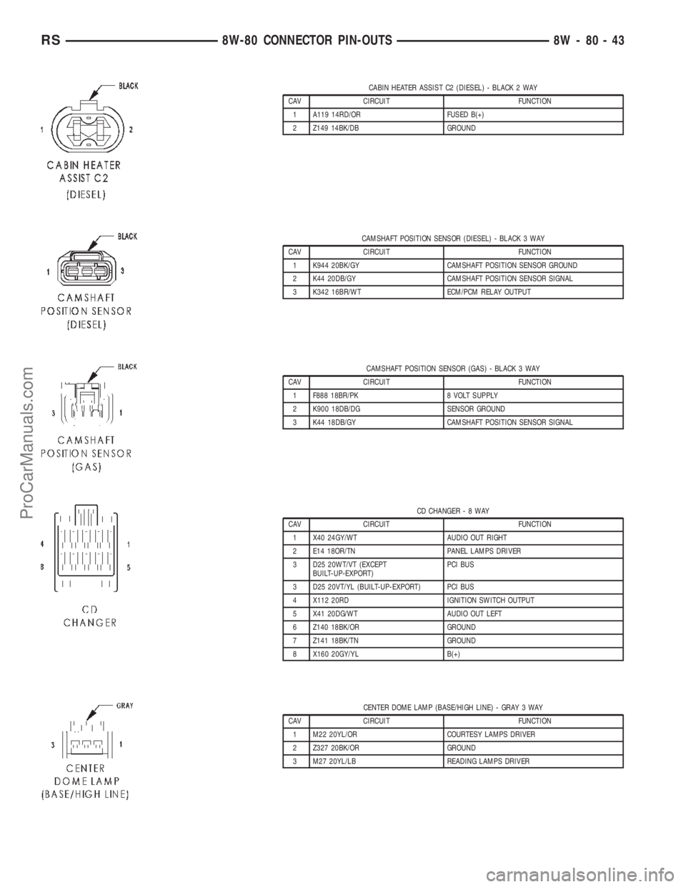
CABIN HEATER ASSIST C2 (DIESEL) - BLACK 2 WAY
CAV CIRCUIT FUNCTION
1 A119 14RD/OR FUSED B(+)
2 Z149 14BK/DB GROUND
CAMSHAFT POSITION SENSOR (DIESEL) - BLACK 3 WAY
CAV CIRCUIT FUNCTION
1 K944 20BK/GY CAMSHAFT POSITION SENSOR GROUND
2 K44 20DB/GY CAMSHAFT POSITION SENSOR SIGNAL
3 K342 16BR/WT ECM/PCM RELAY OUTPUT
CAMSHAFT POSITION SENSOR (GAS) - BLACK 3 WAY
CAV CIRCUIT FUNCTION
1 F888 18BR/PK 8 VOLT SUPPLY
2 K900 18DB/DG SENSOR GROUND
3 K44 18DB/GY CAMSHAFT POSITION SENSOR SIGNAL
CD CHANGER-8WAY
CAV CIRCUIT FUNCTION
1 X40 24GY/WT AUDIO OUT RIGHT
2 E14 18OR/TN PANEL LAMPS DRIVER
3 D25 20WT/VT (EXCEPT
BUILT-UP-EXPORT)PCI BUS
3 D25 20VT/YL (BUILT-UP-EXPORT) PCI BUS
4 X112 20RD IGNITION SWITCH OUTPUT
5 X41 20DG/WT AUDIO OUT LEFT
6 Z140 18BK/OR GROUND
7 Z141 18BK/TN GROUND
8 X160 20GY/YL B(+)
CENTER DOME LAMP (BASE/HIGH LINE) - GRAY 3 WAY
CAV CIRCUIT FUNCTION
1 M22 20YL/OR COURTESY LAMPS DRIVER
2 Z327 20BK/OR GROUND
3 M27 20YL/LB READING LAMPS DRIVER
RS8W-80 CONNECTOR PIN-OUTS8W-80-43
ProCarManuals.com
Page 1150 of 2399
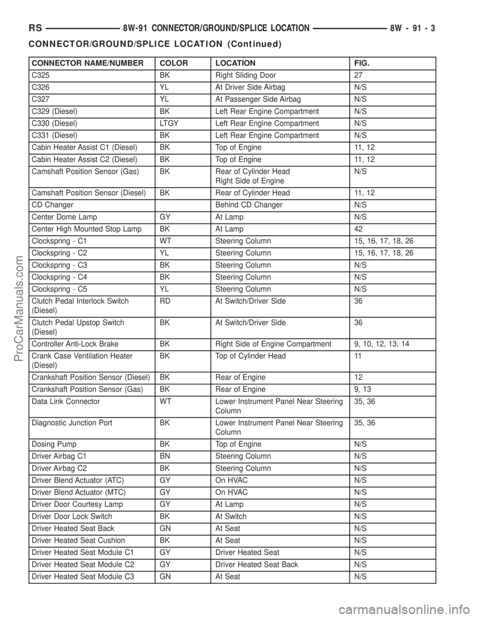
CONNECTOR NAME/NUMBER COLOR LOCATION FIG.
C325 BK Right Sliding Door 27
C326 YL At Driver Side Airbag N/S
C327 YL At Passenger Side Airbag N/S
C329 (Diesel) BK Left Rear Engine Compartment N/S
C330 (Diesel) LTGY Left Rear Engine Compartment N/S
C331 (Diesel) BK Left Rear Engine Compartment N/S
Cabin Heater Assist C1 (Diesel) BK Top of Engine 11, 12
Cabin Heater Assist C2 (Diesel) BK Top of Engine 11, 12
Camshaft Position Sensor (Gas) BK Rear of Cylinder Head
Right Side of EngineN/S
Camshaft Position Sensor (Diesel) BK Rear of Cylinder Head 11, 12
CD Changer Behind CD Changer N/S
Center Dome Lamp GY At Lamp N/S
Center High Mounted Stop Lamp BK At Lamp 42
Clockspring - C1 WT Steering Column 15, 16, 17, 18, 26
Clockspring - C2 YL Steering Column 15, 16, 17, 18, 26
Clockspring - C3 BK Steering Column N/S
Clockspring - C4 BK Steering Column N/S
Clockspring - C5 YL Steering Column N/S
Clutch Pedal Interlock Switch
(Diesel)RD At Switch/Driver Side 36
Clutch Pedal Upstop Switch
(Diesel)BK At Switch/Driver Side 36
Controller Anti-Lock Brake BK Right Side of Engine Compartment 9, 10, 12, 13, 14
Crank Case Ventilation Heater
(Diesel)BK Top of Cylinder Head 11
Crankshaft Position Sensor (Diesel) BK Rear of Engine 12
Crankshaft Position Sensor (Gas) BK Rear of Engine 9, 13
Data Link Connector WT Lower Instrument Panel Near Steering
Column35, 36
Diagnostic Junction Port BK Lower Instrument Panel Near Steering
Column35, 36
Dosing Pump BK Top of Engine N/S
Driver Airbag C1 BN Steering Column N/S
Driver Airbag C2 BK Steering Column N/S
Driver Blend Actuator (ATC) GY On HVAC N/S
Driver Blend Actuator (MTC) GY On HVAC N/S
Driver Door Courtesy Lamp GY At Lamp N/S
Driver Door Lock Switch BK At Switch N/S
Driver Heated Seat Back GN At Seat N/S
Driver Heated Seat Cushion BK At Seat N/S
Driver Heated Seat Module C1 GY Driver Heated Seat N/S
Driver Heated Seat Module C2 GY Driver Heated Seat Back N/S
Driver Heated Seat Module C3 GN At Seat N/S
RS8W-91 CONNECTOR/GROUND/SPLICE LOCATION8W-91-3
CONNECTOR/GROUND/SPLICE LOCATION (Continued)
ProCarManuals.com
Page 1579 of 2399
ASSEMBLY...........................115
SHIFT INTERLOCK SOLENOID
DESCRIPTION........................115
OPERATION..........................115
DIAGNOSIS AND TESTING - BRAKE/
TRANSMISSION SHIFT INTERLOCK
SOLENOID..........................117
REMOVAL............................117
INSTALLATION........................118
SOLENOID - TCC
DESCRIPTION........................119
OPERATION..........................119
REMOVAL............................119
INSTALLATION........................120
THROTTLE VALVE CABLE
REMOVAL............................120
INSTALLATION........................121
ADJUSTMENTS
THROTTLE VALVE LINKAGE
ADJUSTMENT.......................122
TORQUE CONVERTER
DESCRIPTION........................122
OPERATION..........................126
REMOVAL............................127
INSTALLATION........................127
TRANSFER SYSTEM - OUTPUT SHAFT/GEAR/
BEARING
REMOVAL............................128INSTALLATION........................131
ADJUSTMENTS
ADJUSTMENT - OUTPUT SHAFT BEARING . 135
TRANSFER SYSTEM - TRANSFER SHAFT/
GEAR/BEARING
REMOVAL............................137
INSTALLATION........................141
ADJUSTMENTS
ADJUSTMENT - TRANSFER SHAFT
BEARING...........................145
VALVE BODY
REMOVAL............................146
DISASSEMBLY........................148
CLEANING...........................154
INSPECTION.........................155
ASSEMBLY...........................155
INSTALLATION........................158
ADJUSTMENTS
HYDRAULIC CONTROL PRESSURE
ADJUSTMENTS......................160
VEHICLE SPEED SENSOR/PINION GEAR
REMOVAL............................160
INSTALLATION........................160
31TH AUTOMATIC
TRANSAXLE
DESCRIPTION
This transaxle combines torque converter, three
speed transmission, final drive gearing, and differen-
tial into a front wheel drive system.
Within this transaxle, there are three primary
areas:
(1) Main center line plus valve body.
(2) Transfer shaft center line (includes governor
and parking sprag).
(3) Differential center line.
Center distances between the main rotating parts
in these three areas are held precise to maintain a
low noise level.
The torque converter, transaxle area, and differen-
tial are housed in an integral aluminum die casting.
The differential oil sump is common with the
transaxle sump. Separate filling of the differen-
tial is NOT necessary.
The torque converter is attached to the crankshaft
through a flexible driving plate. Cooling of the con-
verter is accomplished by circulating the transaxle
fluid through a remote cooler. There are two types of
coolers used. An oil-to-water type cooler located in
the radiator side tank and/or an oil-to-air heatexchanger. The torque converter assembly is a sealed
unit that cannot be disassembled.
The transaxle fluid is filtered by an internal filter
attached to the lower side of the valve body assembly.
Engine torque is transmitted to the torque con-
verter and then through the input shaft to multiple-
disc clutches in the transaxle. The power flow
depends on the application of the clutches and bands.
Refer to Elements in Use Chart in Diagnosis and
Tests section.
The transaxle consists of:
²Two multiple-disc clutches
²An overrunning clutch
²Two servos
²A hydraulic accumulator
²Two bands
²Two planetary gear sets
This provides three forward ratios and a reverse
ratio. The common sun gear of the planetary gear
sets is connected to the front clutch by a driving
shell. The driving shell is splined to the sun gear and
front clutch retainer. The hydraulic system consists
of an oil pump and a single valve body which con-
tains all of the valves except the governor valves.
The transaxle sump and differential sump are both
vented through the dipstick. Output torque from the
main center line is delivered through helical gears to
the transfer shaft. This gear set is a factor in the
transaxle final drive (axle) ratio. The shaft also car-
21 - 22 31TH AUTOMATIC TRANSAXLERS
ProCarManuals.com
Page 1629 of 2399
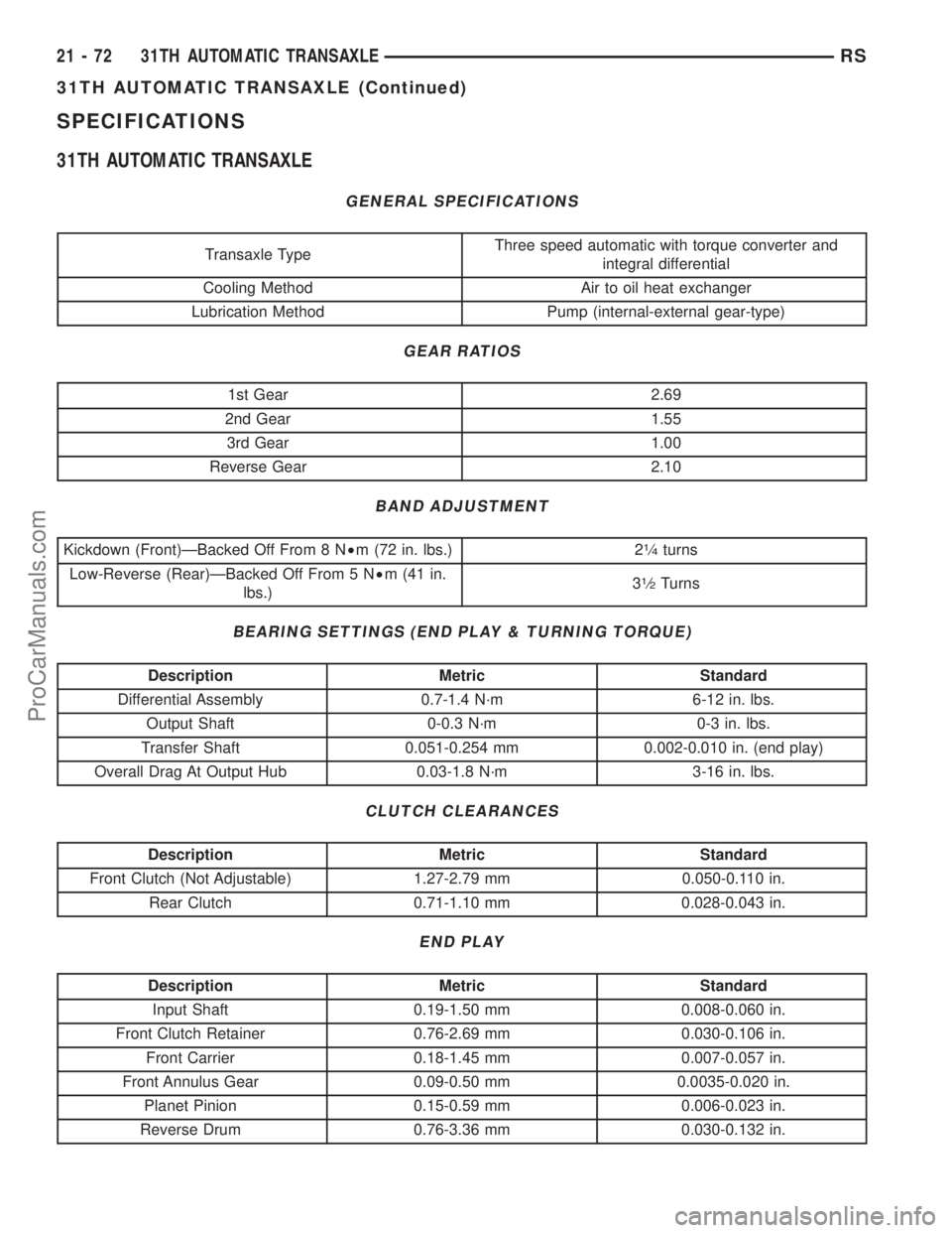
SPECIFICATIONS
31TH AUTOMATIC TRANSAXLE
GENERAL SPECIFICATIONS
Transaxle TypeThree speed automatic with torque converter and
integral differential
Cooling Method Air to oil heat exchanger
Lubrication Method Pump (internal-external gear-type)
GEAR RATIOS
1st Gear 2.69
2nd Gear 1.55
3rd Gear 1.00
Reverse Gear 2.10
BAND ADJUSTMENT
Kickdown (Front)ÐBacked Off From 8 N²m (72 in. lbs.) 21¤4turns
Low-Reverse (Rear)ÐBacked Off From 5 N²m (41 in.
lbs.)3
1¤2Turns
BEARING SETTINGS (END PLAY & TURNING TORQUE)
Description Metric Standard
Differential Assembly 0.7-1.4 N´m 6-12 in. lbs.
Output Shaft 0-0.3 N´m 0-3 in. lbs.
Transfer Shaft 0.051-0.254 mm 0.002-0.010 in. (end play)
Overall Drag At Output Hub 0.03-1.8 N´m 3-16 in. lbs.
CLUTCH CLEARANCES
Description Metric Standard
Front Clutch (Not Adjustable) 1.27-2.79 mm 0.050-0.110 in.
Rear Clutch 0.71-1.10 mm 0.028-0.043 in.
END PLAY
Description Metric Standard
Input Shaft 0.19-1.50 mm 0.008-0.060 in.
Front Clutch Retainer 0.76-2.69 mm 0.030-0.106 in.
Front Carrier 0.18-1.45 mm 0.007-0.057 in.
Front Annulus Gear 0.09-0.50 mm 0.0035-0.020 in.
Planet Pinion 0.15-0.59 mm 0.006-0.023 in.
Reverse Drum 0.76-3.36 mm 0.030-0.132 in.
21 - 72 31TH AUTOMATIC TRANSAXLERS
31TH AUTOMATIC TRANSAXLE (Continued)
ProCarManuals.com
Page 1785 of 2399
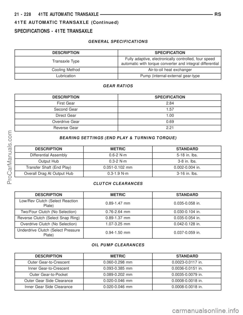
SPECIFICATIONS - 41TE TRANSAXLE
GENERAL SPECIFICATIONS
DESCRIPTION SPECIFICATION
Transaxle TypeFully adaptive, electronically controlled, four speed
automatic with torque converter and integral differential
Cooling Method Air-to-oil heat exchanger
Lubrication Pump (internal-external gear-type
GEAR RATIOS
DESCRIPTION SPECIFICATION
First Gear 2.84
Second Gear 1.57
Direct Gear 1.00
Overdrive Gear 0.69
Reverse Gear 2.21
BEARING SETTINGS (END PLAY & TURNING TORQUE)
DESCRIPTION METRIC STANDARD
Differential Assembly 0.6-2 N´m 5-18 in. lbs.
Output Hub 0.3-2 N´m 3-8 in. lbs.
Transfer Shaft (End Play) 0.051-0.102 mm 0.002-0.004 in.
Overall Drag At Output Hub 0.3-1.9 N´m 3-16 in. lbs.
CLUTCH CLEARANCES
DESCRIPTION METRIC STANDARD
Low/Rev Clutch (Select Reaction
Plate)0.89-1.47 mm 0.035-0.058 in.
Two/Four Clutch (No Selection) 0.76-2.64 mm 0.030-0.104 in.
Reverse Clutch (Select Snap Ring) 0.89-1.37 mm 0.035-0.054 in.
Overdrive Clutch (No Selection) 1.07-3.25 mm 0.042-0.128 in.
Underdrive Clutch (Select Pressure
Plate)0.94-1.50 mm 0.037-0.059 in.
OIL PUMP CLEARANCES
DESCRIPTION METRIC STANDARD
Outer Gear-to-Crescent 0.060-0.298 mm 0.0023-0.0117 in.
Inner Gear-to-Crescent 0.093-0.385 mm 0.0036-0.0151 in.
Outer Gear-to-Pocket 0.089-0.202 mm 0.0035-0.0079 in.
Outer Gear Side Clearance 0.020-0.046 mm 0.0008-0.0018 in.
Inner Gear Side Clearance 0.020-0.046 mm 0.0008-0.0018 in.
21 - 228 41TE AUTOMATIC TRANSAXLERS
41TE AUTOMATIC TRANSAXLE (Continued)
ProCarManuals.com
Page 1972 of 2399
NOTE: Use the following procedure to retrain all
four (4) road wheel tire pressure sensors. No
attempt should be made to retrain individual sen-
sors.
(1) Retrieve Re-learn Magnet, Special Tool 8821.
(2) Press MENU Button on EVIC until9RETRAIN
TIRE SENSORS - NO9is displayed.
(3) Press STEP button to select9YES9.
NOTE: There is a 60 second timer for training the
first sensor and a 30 second timer between training
the remaining sensors. If either of these timers
expire, the EVIC will abort the training procedure.
NOTE: If at any time the EVIC display reads(TRAIN-
ING ABORTED(, move the vehicle ahead at least
one foot and repeat the entire retraining procedure.
(4) Press MENU button to start retraining. Dis-
play will read9TRAIN LEFT FRONT TIRE9
NOTE: The order for retraining all five sensors is:
²Left Front
²Right Front
²Right Rear
²Left Rear
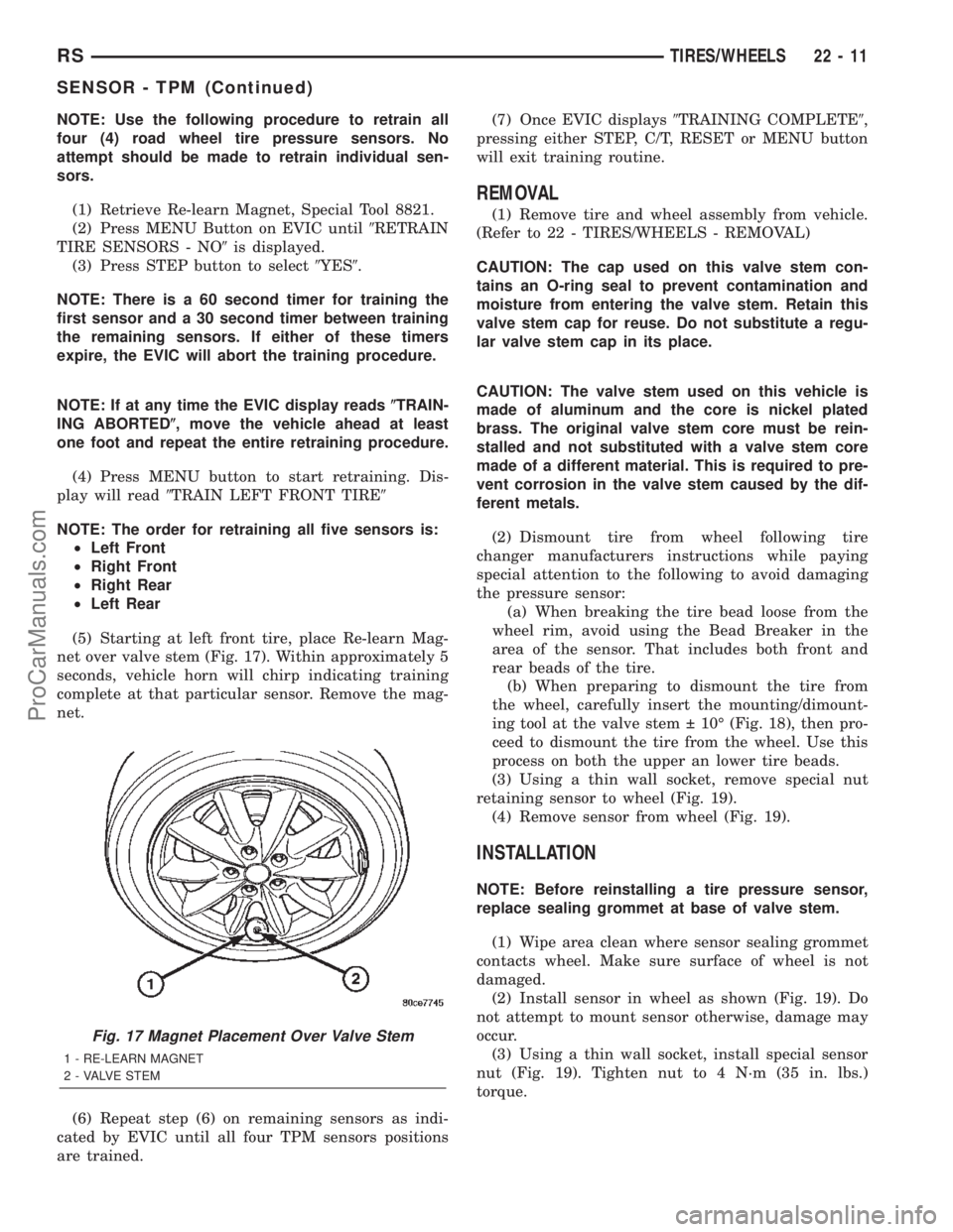
(5) Starting at left front tire, place Re-learn Mag-
net over valve stem (Fig. 17). Within approximately 5
seconds, vehicle horn will chirp indicating training
complete at that particular sensor. Remove the mag-
net.
(6) Repeat step (6) on remaining sensors as indi-
cated by EVIC until all four TPM sensors positions
are trained.(7) Once EVIC displays9TRAINING COMPLETE9,
pressing either STEP, C/T, RESET or MENU button
will exit training routine.
REMOVAL
(1) Remove tire and wheel assembly from vehicle.
(Refer to 22 - TIRES/WHEELS - REMOVAL)
CAUTION: The cap used on this valve stem con-
tains an O-ring seal to prevent contamination and
moisture from entering the valve stem. Retain this
valve stem cap for reuse. Do not substitute a regu-
lar valve stem cap in its place.
CAUTION: The valve stem used on this vehicle is
made of aluminum and the core is nickel plated
brass. The original valve stem core must be rein-
stalled and not substituted with a valve stem core
made of a different material. This is required to pre-
vent corrosion in the valve stem caused by the dif-
ferent metals.
(2) Dismount tire from wheel following tire
changer manufacturers instructions while paying
special attention to the following to avoid damaging
the pressure sensor:
(a) When breaking the tire bead loose from the
wheel rim, avoid using the Bead Breaker in the
area of the sensor. That includes both front and
rear beads of the tire.
(b) When preparing to dismount the tire from
the wheel, carefully insert the mounting/dimount-
ing tool at the valve stem 10É (Fig. 18), then pro-
ceed to dismount the tire from the wheel. Use this
process on both the upper an lower tire beads.
(3) Using a thin wall socket, remove special nut
retaining sensor to wheel (Fig. 19).
(4) Remove sensor from wheel (Fig. 19).
INSTALLATION
NOTE: Before reinstalling a tire pressure sensor,
replace sealing grommet at base of valve stem.
(1) Wipe area clean where sensor sealing grommet
contacts wheel. Make sure surface of wheel is not
damaged.
(2) Install sensor in wheel as shown (Fig. 19). Do
not attempt to mount sensor otherwise, damage may
occur.
(3) Using a thin wall socket, install special sensor
nut (Fig. 19). Tighten nut to 4 N´m (35 in. lbs.)
torque.
Fig. 17 Magnet Placement Over Valve Stem
1 - RE-LEARN MAGNET
2 - VALVE STEM
RSTIRES/WHEELS22-11
SENSOR - TPM (Continued)
ProCarManuals.com