2002 CHRYSLER CARAVAN belt
[x] Cancel search: beltPage 1316 of 2399
(4) Remove camshaft thrust plate (Fig. 47).
(5) Install a long bolt into front of camshaft to
facilitate removal of the camshaft.
(6) Remove the camshaft (Fig. 47), being careful
not to damage cam bearings with the cam lobes.
NOTE: The camshaft bearings are serviced with the
engine block.
INSPECTION
(1) Check the cam lobes and bearing surfaces for
abnormal wear and damage (Fig. 49). Replace cam-
shaft as required.
NOTE: If camshaft is replaced due to lobe wear or
damage, always replace the lifters.
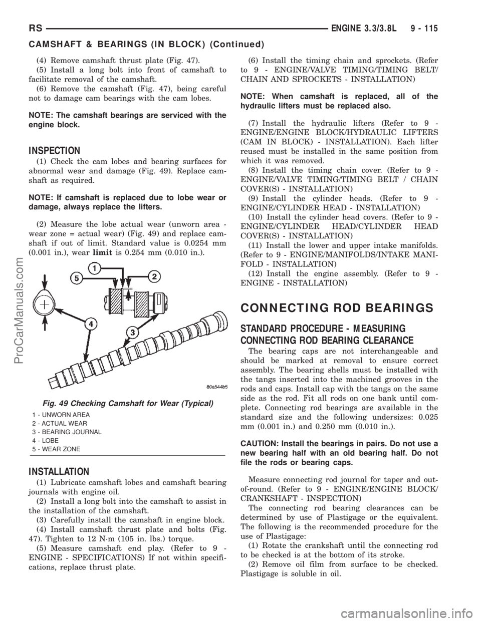
(2) Measure the lobe actual wear (unworn area -
wear zone = actual wear) (Fig. 49) and replace cam-
shaft if out of limit. Standard value is 0.0254 mm
(0.001 in.), wearlimitis 0.254 mm (0.010 in.).
INSTALLATION
(1) Lubricate camshaft lobes and camshaft bearing
journals with engine oil.
(2) Install a long bolt into the camshaft to assist in
the installation of the camshaft.
(3) Carefully install the camshaft in engine block.
(4) Install camshaft thrust plate and bolts (Fig.
47). Tighten to 12 N´m (105 in. lbs.) torque.
(5) Measure camshaft end play. (Refer to 9 -
ENGINE - SPECIFICATIONS) If not within specifi-
cations, replace thrust plate.(6) Install the timing chain and sprockets. (Refer
to 9 - ENGINE/VALVE TIMING/TIMING BELT/
CHAIN AND SPROCKETS - INSTALLATION)
NOTE: When camshaft is replaced, all of the
hydraulic lifters must be replaced also.
(7) Install the hydraulic lifters (Refer to 9 -
ENGINE/ENGINE BLOCK/HYDRAULIC LIFTERS
(CAM IN BLOCK) - INSTALLATION). Each lifter
reused must be installed in the same position from
which it was removed.
(8) Install the timing chain cover. (Refer to 9 -
ENGINE/VALVE TIMING/TIMING BELT / CHAIN
COVER(S) - INSTALLATION)
(9) Install the cylinder heads. (Refer to 9 -
ENGINE/CYLINDER HEAD - INSTALLATION)
(10) Install the cylinder head covers. (Refer to 9 -
ENGINE/CYLINDER HEAD/CYLINDER HEAD
COVER(S) - INSTALLATION)
(11) Install the lower and upper intake manifolds.
(Refer to 9 - ENGINE/MANIFOLDS/INTAKE MANI-
FOLD - INSTALLATION)
(12) Install the engine assembly. (Refer to 9 -
ENGINE - INSTALLATION)
CONNECTING ROD BEARINGS
STANDARD PROCEDURE - MEASURING
CONNECTING ROD BEARING CLEARANCE
The bearing caps are not interchangeable and
should be marked at removal to ensure correct
assembly. The bearing shells must be installed with
the tangs inserted into the machined grooves in the
rods and caps. Install cap with the tangs on the same
side as the rod. Fit all rods on one bank until com-
plete. Connecting rod bearings are available in the
standard size and the following undersizes: 0.025
mm (0.001 in.) and 0.250 mm (0.010 in.).
CAUTION: Install the bearings in pairs. Do not use a
new bearing half with an old bearing half. Do not
file the rods or bearing caps.
Measure connecting rod journal for taper and out-
of-round. (Refer to 9 - ENGINE/ENGINE BLOCK/
CRANKSHAFT - INSPECTION)
The connecting rod bearing clearances can be
determined by use of Plastigage or the equivalent.
The following is the recommended procedure for the
use of Plastigage:
(1) Rotate the crankshaft until the connecting rod
to be checked is at the bottom of its stroke.
(2) Remove oil film from surface to be checked.
Plastigage is soluble in oil.
Fig. 49 Checking Camshaft for Wear (Typical)
1 - UNWORN AREA
2 - ACTUAL WEAR
3 - BEARING JOURNAL
4 - LOBE
5 - WEAR ZONE
RSENGINE 3.3/3.8L9 - 115
CAMSHAFT & BEARINGS (IN BLOCK) (Continued)
ProCarManuals.com
Page 1318 of 2399
DESCRIPTION - 3.8L
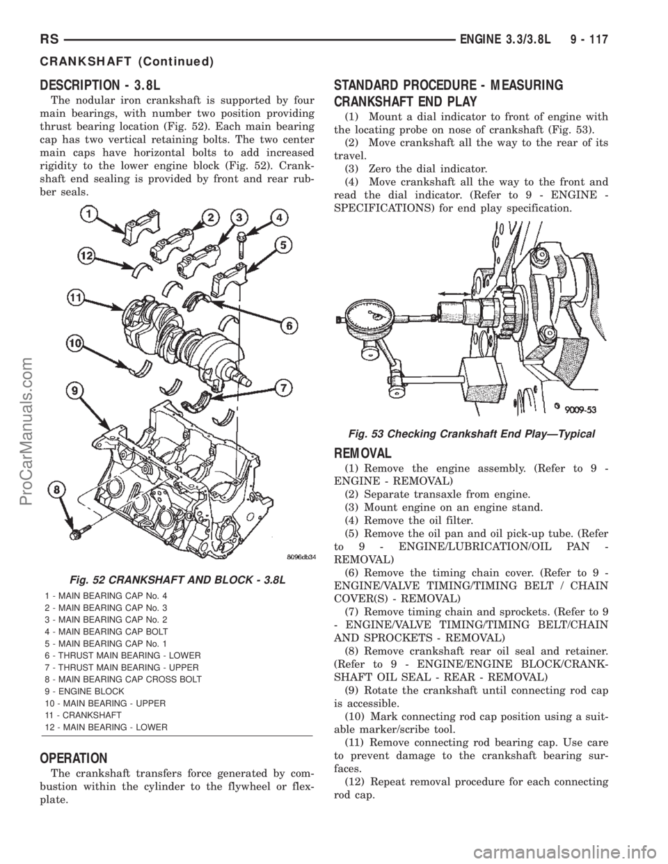
The nodular iron crankshaft is supported by four
main bearings, with number two position providing
thrust bearing location (Fig. 52). Each main bearing
cap has two vertical retaining bolts. The two center
main caps have horizontal bolts to add increased
rigidity to the lower engine block (Fig. 52). Crank-
shaft end sealing is provided by front and rear rub-
ber seals.
OPERATION
The crankshaft transfers force generated by com-
bustion within the cylinder to the flywheel or flex-
plate.
STANDARD PROCEDURE - MEASURING
CRANKSHAFT END PLAY
(1) Mount a dial indicator to front of engine with
the locating probe on nose of crankshaft (Fig. 53).
(2) Move crankshaft all the way to the rear of its
travel.
(3) Zero the dial indicator.
(4) Move crankshaft all the way to the front and
read the dial indicator. (Refer to 9 - ENGINE -
SPECIFICATIONS) for end play specification.
REMOVAL
(1) Remove the engine assembly. (Refer to 9 -
ENGINE - REMOVAL)
(2) Separate transaxle from engine.
(3) Mount engine on an engine stand.
(4) Remove the oil filter.
(5) Remove the oil pan and oil pick-up tube. (Refer
to 9 - ENGINE/LUBRICATION/OIL PAN -
REMOVAL)
(6) Remove the timing chain cover. (Refer to 9 -
ENGINE/VALVE TIMING/TIMING BELT / CHAIN
COVER(S) - REMOVAL)
(7) Remove timing chain and sprockets. (Refer to 9
- ENGINE/VALVE TIMING/TIMING BELT/CHAIN
AND SPROCKETS - REMOVAL)
(8) Remove crankshaft rear oil seal and retainer.
(Refer to 9 - ENGINE/ENGINE BLOCK/CRANK-
SHAFT OIL SEAL - REAR - REMOVAL)
(9) Rotate the crankshaft until connecting rod cap
is accessible.
(10) Mark connecting rod cap position using a suit-
able marker/scribe tool.
(11) Remove connecting rod bearing cap. Use care
to prevent damage to the crankshaft bearing sur-
faces.
(12) Repeat removal procedure for each connecting
rod cap.
Fig. 52 CRANKSHAFT AND BLOCK - 3.8L
1 - MAIN BEARING CAP No. 4
2 - MAIN BEARING CAP No. 3
3 - MAIN BEARING CAP No. 2
4 - MAIN BEARING CAP BOLT
5 - MAIN BEARING CAP No. 1
6 - THRUST MAIN BEARING - LOWER
7 - THRUST MAIN BEARING - UPPER
8 - MAIN BEARING CAP CROSS BOLT
9 - ENGINE BLOCK
10 - MAIN BEARING - UPPER
11 - CRANKSHAFT
12 - MAIN BEARING - LOWER
Fig. 53 Checking Crankshaft End PlayÐTypical
RSENGINE 3.3/3.8L9 - 117
CRANKSHAFT (Continued)
ProCarManuals.com
Page 1319 of 2399
(13) Remove and discard the main bearing cross
bolts and washers (3.8L engine only).
NOTE: Install new cross bolt and washer assembly
(3.8L engine only) upon reassembly.
(14) Remove the main bearing cap bolts
(15) Remove the main bearing caps.
(16) Remove the crankshaft from engine block.
INSPECTION
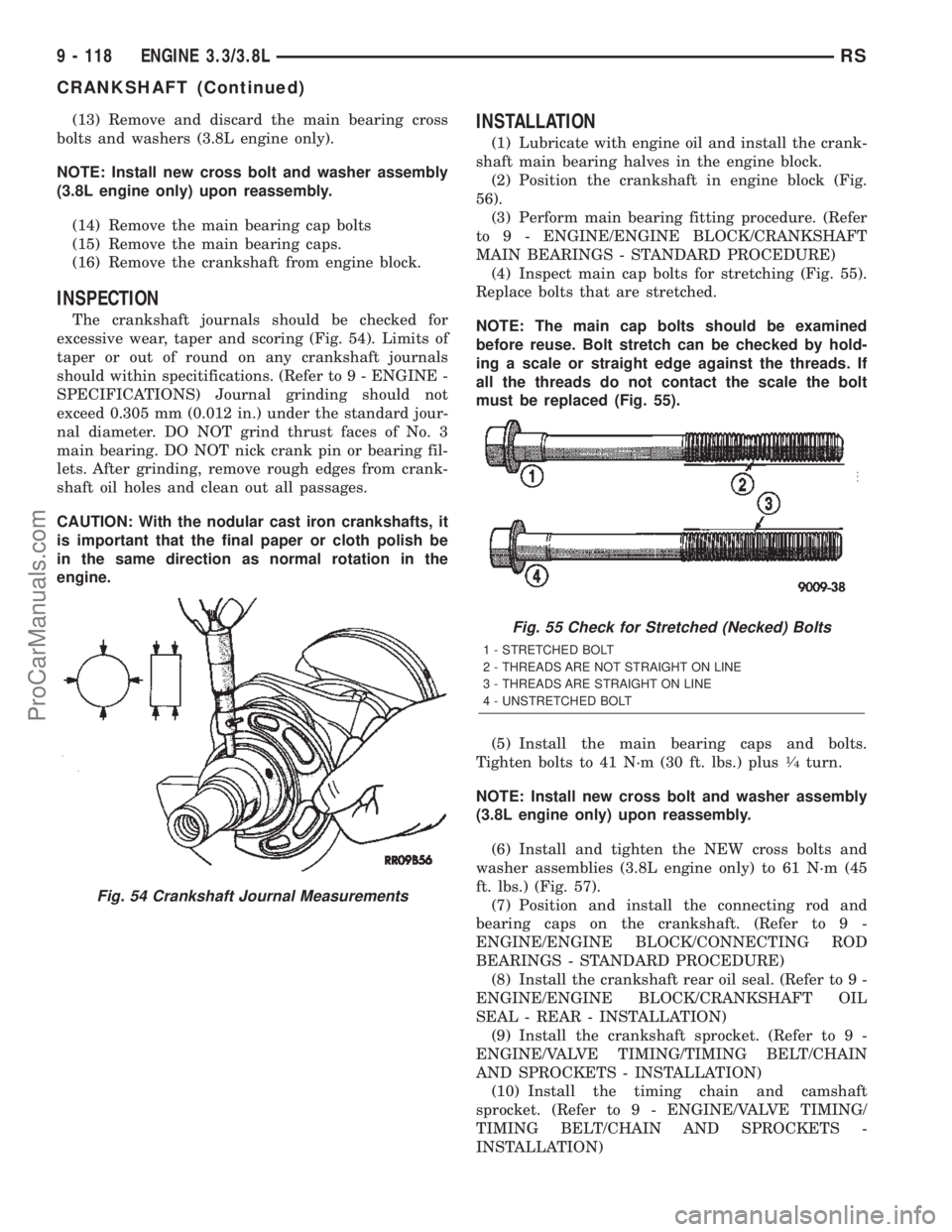
The crankshaft journals should be checked for
excessive wear, taper and scoring (Fig. 54). Limits of
taper or out of round on any crankshaft journals
should within specitifications. (Refer to 9 - ENGINE -
SPECIFICATIONS) Journal grinding should not
exceed 0.305 mm (0.012 in.) under the standard jour-
nal diameter. DO NOT grind thrust faces of No. 3
main bearing. DO NOT nick crank pin or bearing fil-
lets. After grinding, remove rough edges from crank-
shaft oil holes and clean out all passages.
CAUTION: With the nodular cast iron crankshafts, it
is important that the final paper or cloth polish be
in the same direction as normal rotation in the
engine.
INSTALLATION
(1) Lubricate with engine oil and install the crank-
shaft main bearing halves in the engine block.
(2) Position the crankshaft in engine block (Fig.
56).
(3) Perform main bearing fitting procedure. (Refer
to 9 - ENGINE/ENGINE BLOCK/CRANKSHAFT
MAIN BEARINGS - STANDARD PROCEDURE)
(4) Inspect main cap bolts for stretching (Fig. 55).
Replace bolts that are stretched.
NOTE: The main cap bolts should be examined
before reuse. Bolt stretch can be checked by hold-
ing a scale or straight edge against the threads. If
all the threads do not contact the scale the bolt
must be replaced (Fig. 55).
(5) Install the main bearing caps and bolts.
Tighten bolts to 41 N´m (30 ft. lbs.) plus
1¤4turn.
NOTE: Install new cross bolt and washer assembly
(3.8L engine only) upon reassembly.
(6) Install and tighten the NEW cross bolts and
washer assemblies (3.8L engine only) to 61 N´m (45
ft. lbs.) (Fig. 57).
(7) Position and install the connecting rod and
bearing caps on the crankshaft. (Refer to 9 -
ENGINE/ENGINE BLOCK/CONNECTING ROD
BEARINGS - STANDARD PROCEDURE)
(8) Install the crankshaft rear oil seal. (Refer to 9 -
ENGINE/ENGINE BLOCK/CRANKSHAFT OIL
SEAL - REAR - INSTALLATION)
(9) Install the crankshaft sprocket. (Refer to 9 -
ENGINE/VALVE TIMING/TIMING BELT/CHAIN
AND SPROCKETS - INSTALLATION)
(10) Install the timing chain and camshaft
sprocket. (Refer to 9 - ENGINE/VALVE TIMING/
TIMING BELT/CHAIN AND SPROCKETS -
INSTALLATION)
Fig. 54 Crankshaft Journal Measurements
Fig. 55 Check for Stretched (Necked) Bolts
1 - STRETCHED BOLT
2 - THREADS ARE NOT STRAIGHT ON LINE
3 - THREADS ARE STRAIGHT ON LINE
4 - UNSTRETCHED BOLT
9 - 118 ENGINE 3.3/3.8LRS
CRANKSHAFT (Continued)
ProCarManuals.com
Page 1323 of 2399
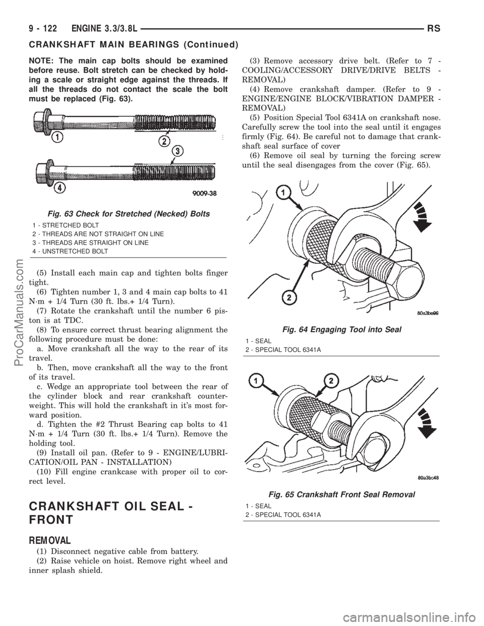
NOTE: The main cap bolts should be examined
before reuse. Bolt stretch can be checked by hold-
ing a scale or straight edge against the threads. If
all the threads do not contact the scale the bolt
must be replaced (Fig. 63).
(5) Install each main cap and tighten bolts finger
tight.
(6) Tighten number 1, 3 and 4 main cap bolts to 41
N´m + 1/4 Turn (30 ft. lbs.+ 1/4 Turn).
(7) Rotate the crankshaft until the number 6 pis-
ton is at TDC.
(8) To ensure correct thrust bearing alignment the
following procedure must be done:
a. Move crankshaft all the way to the rear of its
travel.
b. Then, move crankshaft all the way to the front
of its travel.
c. Wedge an appropriate tool between the rear of
the cylinder block and rear crankshaft counter-
weight. This will hold the crankshaft in it's most for-
ward position.
d. Tighten the #2 Thrust Bearing cap bolts to 41
N´m + 1/4 Turn (30 ft. lbs.+ 1/4 Turn). Remove the
holding tool.
(9) Install oil pan. (Refer to 9 - ENGINE/LUBRI-
CATION/OIL PAN - INSTALLATION)
(10) Fill engine crankcase with proper oil to cor-
rect level.
CRANKSHAFT OIL SEAL -
FRONT
REMOVAL
(1) Disconnect negative cable from battery.
(2) Raise vehicle on hoist. Remove right wheel and
inner splash shield.(3) Remove accessory drive belt. (Refer to 7 -
COOLING/ACCESSORY DRIVE/DRIVE BELTS -
REMOVAL)
(4) Remove crankshaft damper. (Refer to 9 -
ENGINE/ENGINE BLOCK/VIBRATION DAMPER -
REMOVAL)
(5) Position Special Tool 6341A on crankshaft nose.
Carefully screw the tool into the seal until it engages
firmly (Fig. 64). Be careful not to damage that crank-
shaft seal surface of cover
(6) Remove oil seal by turning the forcing screw
until the seal disengages from the cover (Fig. 65).
Fig. 63 Check for Stretched (Necked) Bolts
1 - STRETCHED BOLT
2 - THREADS ARE NOT STRAIGHT ON LINE
3 - THREADS ARE STRAIGHT ON LINE
4 - UNSTRETCHED BOLT
Fig. 64 Engaging Tool into Seal
1 - SEAL
2 - SPECIAL TOOL 6341A
Fig. 65 Crankshaft Front Seal Removal
1 - SEAL
2 - SPECIAL TOOL 6341A
9 - 122 ENGINE 3.3/3.8LRS
CRANKSHAFT MAIN BEARINGS (Continued)
ProCarManuals.com
Page 1324 of 2399
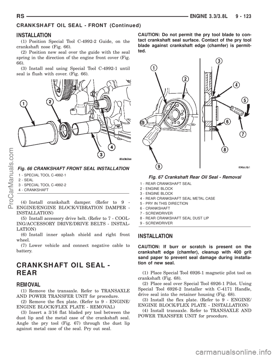
INSTALLATION
(1) Position Special Tool C-4992-2 Guide, on the
crankshaft nose (Fig. 66).
(2) Position new seal over the guide with the seal
spring in the direction of the engine front cover (Fig.
66).
(3) Install seal using Special Tool C-4992-1 until
seal is flush with cover. (Fig. 66).
(4) Install crankshaft damper. (Refer to 9 -
ENGINE/ENGINE BLOCK/VIBRATION DAMPER -
INSTALLATION)
(5) Install accessory drive belt. (Refer to 7 - COOL-
ING/ACCESSORY DRIVE/DRIVE BELTS - INSTAL-
LATION)
(6) Install inner splash shield and right front
wheel.
(7) Lower vehicle and connect negative cable to
battery.
CRANKSHAFT OIL SEAL -
REAR
REMOVAL
(1) Remove the transaxle. Refer to TRANSAXLE
AND POWER TRANSFER UNIT for procedure.
(2) Remove the flex plate. (Refer to 9 - ENGINE/
ENGINE BLOCK/FLEX PLATE - REMOVAL)
(3) Insert a 3/16 flat bladed pry tool between the
dust lip and the metal case of the crankshaft seal.
Angle the pry tool (Fig. 67) through the dust lip
against metal case of the seal. Pry out seal.CAUTION: Do not permit the pry tool blade to con-
tact crankshaft seal surface. Contact of the pry tool
blade against crankshaft edge (chamfer) is permit-
ted.
INSTALLATION
CAUTION: If burr or scratch is present on the
crankshaft edge (chamfer), cleanup with 400 grit
sand paper to prevent seal damage during installa-
tion of new seal.
(1) Place Special Tool 6926-1 magnetic pilot tool on
crankshaft (Fig. 68).
(2) Place seal over Special Tool 6926-1 Pilot. Using
Special Tool 6926-2 Installer with C-4171 Handle,
drive seal into the retainer housing (Fig. 68).
(3) Install the flex plate. (Refer to 9 - ENGINE/
ENGINE BLOCK/FLEX PLATE - INSTALLATION)
(4) Install transaxle. Refer to TRANSAXLE AND
POWER TRANSFER UNIT for procedure.
Fig. 66 CRANKSHAFT FRONT SEAL INSTALLATION
1 - SPECIAL TOOL C-4992-1
2 - SEAL
3 - SPECIAL TOOL C-4992-2
4 - CRANKSHAFTFig. 67 Crankshaft Rear Oil Seal - Removal
1 - REAR CRANKSHAFT SEAL
2 - ENGINE BLOCK
3 - ENGINE BLOCK
4 - REAR CRANKSHAFT SEAL METAL CASE
5 - PRY IN THIS DIRECTION
6 - CRANKSHAFT
7 - SCREWDRIVER
8 - REAR CRANKSHAFT SEAL DUST LIP
9 - SCREWDRIVER
RSENGINE 3.3/3.8L9 - 123
CRANKSHAFT OIL SEAL - FRONT (Continued)
ProCarManuals.com
Page 1333 of 2399
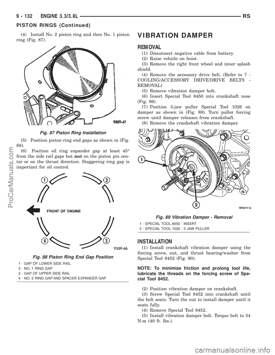
(4) Install No. 2 piston ring and then No. 1 piston
ring (Fig. 87).
(5) Position piston ring end gaps as shown in (Fig.
88).
(6) Position oil ring expander gap at least 45É
from the side rail gaps butnoton the piston pin cen-
ter or on the thrust direction. Staggering ring gap is
important for oil control.VIBRATION DAMPER
REMOVAL
(1) Disconnect negative cable from battery.
(2) Raise vehicle on hoist.
(3) Remove the right front wheel and inner splash
shield.
(4) Remove the accessory drive belt. (Refer to 7 -
COOLING/ACCESSORY DRIVE/DRIVE BELTS -
REMOVAL)
(5) Remove vibration damper bolt.
(6) Insert Special Tool 8450 into crankshaft nose
(Fig. 89).
(7) Position 3-jaw puller Special Tool 1026 on
damper as shown in (Fig. 89). Turn puller forcing
screw until damper releases from crankshaft.
(8) Remove the crankshaft vibration damper.
INSTALLATION
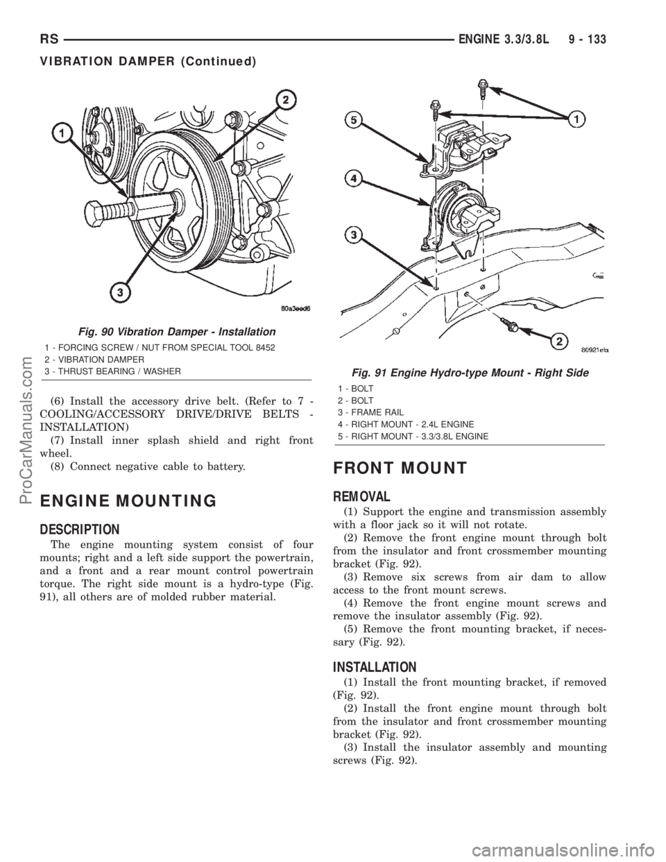
(1) Install crankshaft vibration damper using the
forcing screw, nut, and thrust bearing/washer from
Special Tool 8452 (Fig. 90).
NOTE: To minimize friction and prolong tool life,
lubricate the threads on the forcing screw of Spe-
cial Tool 8452.
(2) Position vibration damper on crankshaft.
(3) Screw Special Tool 8452 into crankshaft until
the bolt seats. Turn the nut to install damper until it
seats fully.
(4) Remove Special Tool 8452.
(5) Install vibration damper bolt. Torque bolt to 54
N´m (40 ft. lbs.).
Fig. 87 Piston Ring Installation
Fig. 88 Piston Ring End Gap Position
1 - GAP OF LOWER SIDE RAIL
2 - NO. 1 RING GAP
3 - GAP OF UPPER SIDE RAIL
4 - NO. 2 RING GAP AND SPACER EXPANDER GAP
Fig. 89 Vibration Damper - Removal
1 - SPECIAL TOOL 8450 - INSERT
2 - SPECIAL TOOL 1026-3JAWPULLER
9 - 132 ENGINE 3.3/3.8LRS
PISTON RINGS (Continued)
ProCarManuals.com
Page 1334 of 2399
(6) Install the accessory drive belt. (Refer to 7 -
COOLING/ACCESSORY DRIVE/DRIVE BELTS -
INSTALLATION)
(7) Install inner splash shield and right front
wheel.
(8) Connect negative cable to battery.
ENGINE MOUNTING
DESCRIPTION
The engine mounting system consist of four
mounts; right and a left side support the powertrain,
and a front and a rear mount control powertrain
torque. The right side mount is a hydro-type (Fig.
91), all others are of molded rubber material.
FRONT MOUNT
REMOVAL
(1) Support the engine and transmission assembly
with a floor jack so it will not rotate.
(2) Remove the front engine mount through bolt
from the insulator and front crossmember mounting
bracket (Fig. 92).
(3) Remove six screws from air dam to allow
access to the front mount screws.
(4) Remove the front engine mount screws and
remove the insulator assembly (Fig. 92).
(5) Remove the front mounting bracket, if neces-
sary (Fig. 92).
INSTALLATION
(1) Install the front mounting bracket, if removed
(Fig. 92).
(2) Install the front engine mount through bolt
from the insulator and front crossmember mounting
bracket (Fig. 92).
(3) Install the insulator assembly and mounting
screws (Fig. 92).
Fig. 90 Vibration Damper - Installation
1 - FORCING SCREW / NUT FROM SPECIAL TOOL 8452
2 - VIBRATION DAMPER
3 - THRUST BEARING / WASHER
Fig. 91 Engine Hydro-type Mount - Right Side
1 - BOLT
2 - BOLT
3 - FRAME RAIL
4 - RIGHT MOUNT - 2.4L ENGINE
5 - RIGHT MOUNT - 3.3/3.8L ENGINE
RSENGINE 3.3/3.8L9 - 133
VIBRATION DAMPER (Continued)
ProCarManuals.com
Page 1342 of 2399
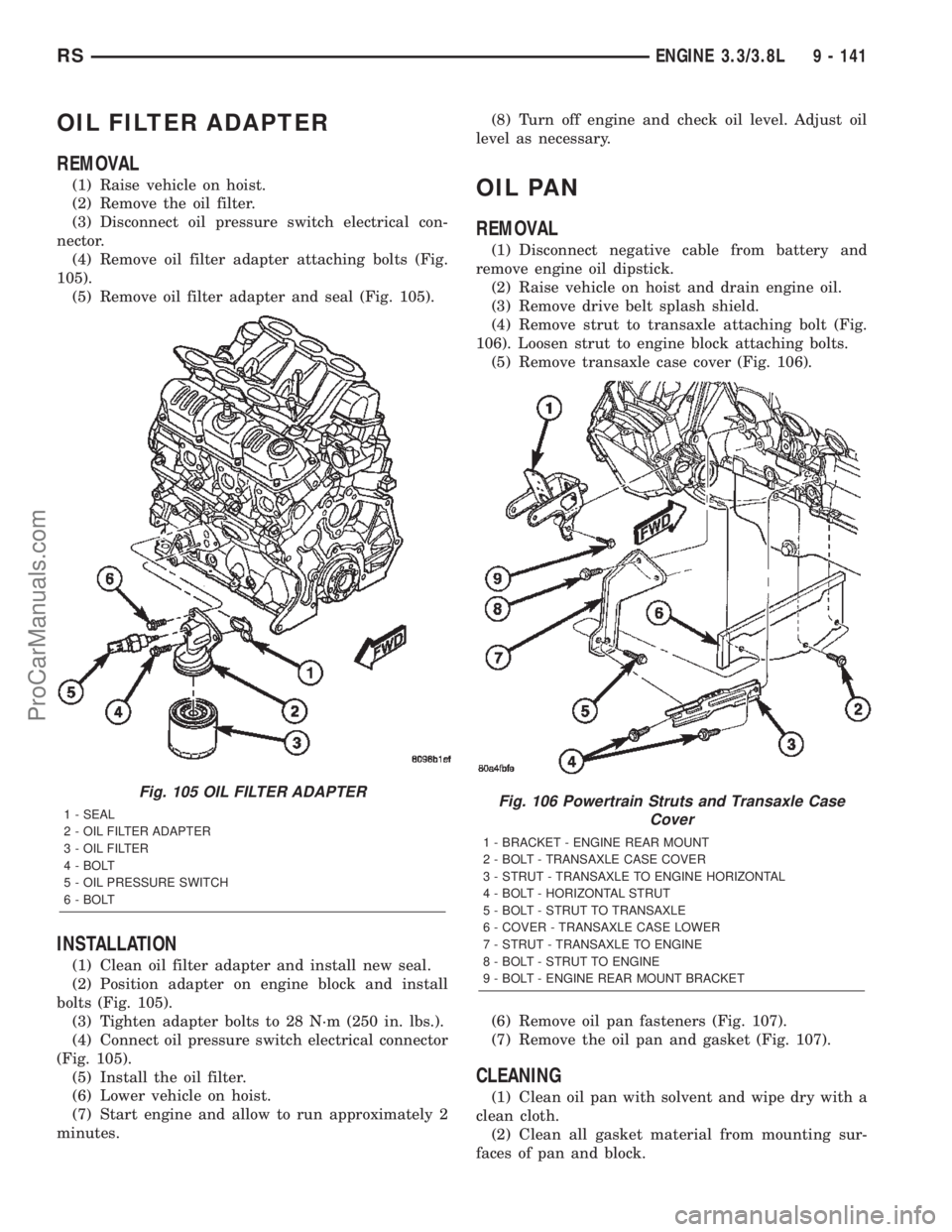
OIL FILTER ADAPTER
REMOVAL
(1) Raise vehicle on hoist.
(2) Remove the oil filter.
(3) Disconnect oil pressure switch electrical con-
nector.
(4) Remove oil filter adapter attaching bolts (Fig.
105).
(5) Remove oil filter adapter and seal (Fig. 105).
INSTALLATION
(1) Clean oil filter adapter and install new seal.
(2) Position adapter on engine block and install
bolts (Fig. 105).
(3) Tighten adapter bolts to 28 N´m (250 in. lbs.).
(4) Connect oil pressure switch electrical connector
(Fig. 105).
(5) Install the oil filter.
(6) Lower vehicle on hoist.
(7) Start engine and allow to run approximately 2
minutes.(8) Turn off engine and check oil level. Adjust oil
level as necessary.
OIL PAN
REMOVAL
(1) Disconnect negative cable from battery and
remove engine oil dipstick.
(2) Raise vehicle on hoist and drain engine oil.
(3) Remove drive belt splash shield.
(4) Remove strut to transaxle attaching bolt (Fig.
106). Loosen strut to engine block attaching bolts.
(5) Remove transaxle case cover (Fig. 106).
(6) Remove oil pan fasteners (Fig. 107).
(7) Remove the oil pan and gasket (Fig. 107).
CLEANING
(1) Clean oil pan with solvent and wipe dry with a
clean cloth.
(2) Clean all gasket material from mounting sur-
faces of pan and block.
Fig. 105 OIL FILTER ADAPTER
1 - SEAL
2 - OIL FILTER ADAPTER
3 - OIL FILTER
4 - BOLT
5 - OIL PRESSURE SWITCH
6 - BOLTFig. 106 Powertrain Struts and Transaxle Case
Cover
1 - BRACKET - ENGINE REAR MOUNT
2 - BOLT - TRANSAXLE CASE COVER
3 - STRUT - TRANSAXLE TO ENGINE HORIZONTAL
4 - BOLT - HORIZONTAL STRUT
5 - BOLT - STRUT TO TRANSAXLE
6 - COVER - TRANSAXLE CASE LOWER
7 - STRUT - TRANSAXLE TO ENGINE
8 - BOLT - STRUT TO ENGINE
9 - BOLT - ENGINE REAR MOUNT BRACKET
RSENGINE 3.3/3.8L9 - 141
ProCarManuals.com